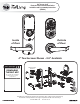
Yale Assure Lock Electronic Interconnected Push Button Installation and Programming Instructions (YRC216) ® ® ® Inside of Door Outside of Door 4" Touchscreen Shown - 5.5" Available Before you begin DOWNLOAD THE BILT APP Network Module (Optional) for step-by-step installation instructions & to register your product Retrofitting or modifying this product may impact fire rating, safety features and warranty. Consult with code specifications to ensure compliance with all codes and ratings.
Before You Begin Template Network Module (Optional) 1/8" 3/32" 1 x2 x2 x2 x8 x1 x2 1/8" 1" 2-1/8" 4-1/2" Min (114) 1-3/8" (35mm) Min to 1-3/4" (44.
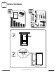
Mark Door Reference Lines EXISTING 2-3/8" or 2-3/4" Backset REMOVE Template CL 3 P/N YRL-EMICL-PBINSTL-FUL Rev A
1 Preparing Door (if necessary) Template 4" or 5.5" Ø2-1/8" 2-3/8" or 2-3/4" ! Drill holes 1/2 way thru door then complete from other side to prevent splitting.
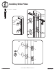
2 Installing Strike Plates 7-16 / 8-32 x 1" UNCWS Frame 1" Dia. x 1"Deep Frame x4 Inside of Door 1" Dia.
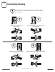
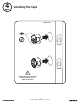
Determining Handing The hand of a door is determined from the secure side of the door. The term "secure" means the side from which you initially unlock and enter. Left Hand “LH”, Hinges Left. Open Inward. Left Hand Reverse "LHR", Hinges Left. Open Outward. Right Hand "RH", Hinges Right. Open Inward. Right Hand Reverse "RHR", Hinges Right. Open Outward.
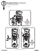
3 Changing Handing (if necessary) 4" Left Hand to 4" Right Hand Shown 4-24 x 1/4" PPHMS x2 ! DO NOT TAMPER WITH OR LOOSEN E-CLIP AND ITS ASSEMBLY ! DO NOT LOOSEN THESE 6 SCREWS OR REMOVE COVER 7 P/N YRL-EMICL-PBINSTL-FUL Rev A
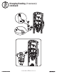
3 Changing Handing (if necessary) continued 8 P/N YRL-EMICL-PBINSTL-FUL Rev A
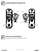
Lockset Handing Configurations For 5.5" For 5.5" For 4" For 4" 4" Right Hand 4" Left Hand Test Lever and Thumbturn After handing is changed, check that lever and thumbturn rotate freely.
4 Installing Fire Cups Inside of Door ! Both Fire Cups and a UL marked Latchbolt must be used to qualify for UL listing.
5 Adjusting Deadbolt Latch (If adjustable deadbolt latch provided) default 2-3/8" position UP O optional 2-3/4" position UP Pull Press 11 P/N YRL-EMICL-PBINSTL-FUL Rev A
6 Installing Deadbolt Latch & Latchbolt 7-16 / 8-32 x 1" UNCWS x4 Inside of Door ! Bolt must be in retracted (unlocked) position before installing. UP ! Ensure arrow stamped on deadbolt is UP. Choose latchbolt based on backset. (2-3/8" or 2-3/4") ! Curved edge of latchbolt faces direction door closes.
7 Installing Exterior Deadbolt M6x55 PPHMS UP x2 Inside of Door UP 13 P/N YRL-EMICL-PBINSTL-FUL Rev A
8 Installing Lock Chassis 10-32 x 1-1/2" PPHMS Inside of Door x2 UP 14 P/N YRL-EMICL-PBINSTL-FUL Rev A
9 Securing Back Plate to Door M4 x 14mm PFHMS Self Tapping x2 Inside of Door UP ! Drill two pilot holes Ø1/8" x 1/2" deep ! Two M4 x 14mm self tapping screws must be used to qualify for UL listing.
Testing Deadbolt & Latchbolt Operation Outside of Door 16 P/N YRL-EMICL-PBINSTL-FUL Rev A
10 Attaching the Cable Assembly ! Test that cables are securely connected. Inside of Door ! Cable must be routed as shown to avoid interference with movement of lock.
11 Installing Interior Lock ! Orientation must match. Do not fasten lock to back plate until properly fitted. Inside of Door ! UP Turn thumbturn to adjust slot orientation.
11 Installing Interior Lock continued 10-32 x 5/8" POHMS 6-32 x 1" PPHMS x1 x2 Inside of Door ! DO NOT LOOSEN THIS SCREW 19 P/N YRL-EMICL-PBINSTL-FUL Rev A
12 Installing Interior Lever Inside of Door "SNAP" Inside of Door Pull lever to ensure it is secure.
Testing Final Latchbolt Operation Inside of Door Outside of Door 21 P/N YRL-EMICL-PBINSTL-FUL Rev A
Testing Final Deadbolt Operation 22 P/N YRL-EMICL-PBINSTL-FUL Rev A
Testing Final Deadbolt Operation ! If testing fails, go back to beginning of Step 11 and check installation.
13 Installing Optional Network Module ! DO NOT install network module with batteries in unit. Damage may occur. 14 Installing Batteries & Cover Tighten screw to replace cover. ! Bolt must be in retracted (unlocked) position before installing batteries.
Handing the Lock AFTER installing batteries and cover or AFTER a factory reset, create Master PIN code. See 1 of Programming Instructions. After entering the Master PIN code: Press Advanced Lock Settings Press to Select Press Handing the Lock Press to Select Press to complete Lock will cycle motor to complete handing. Congratulations, you've installed the Yale Assure Lock Electronic Interconnected Push Button! Continue with the Programming Instructions to customize your product.
Hardware Troubleshooting Cycle lock in both the locked and unlocked positions. If problems are found: Bolt will not extend and motor is grinding a. Enter your Master PIN code. b. With the bolt retracted, press menu Option 3 for Advanced Lock Settings. c. Press Option 5 to rehand the lock. d. Test the operation; locking the door via the keypad. Door is binding a. Check that door and frame are properly aligned and door is free swinging. b.
Changing Lock: Replacing Cylinder A B D E F C 1. To remove cylinder: A. Remove keypad from door. B. Remove rubber gasket. C. Remove two screws holding plastic guide in place. D. Remove plastic guide. E. Remove screw with washer holding cylinder in place (visible after removing plastic guide). F. Remove cylinder housing by pulling cylinder tailpiece away from keypad. 2. To Install new cylinder: A. Reverse previous steps for removing cylinder.
Programming Instructions Low Battery WarningFlashes RED Lock-out ModeKeypad Flashes Interior Lock Privacy Mode Button Keypad Master PIN Code must be created before any further programming.
1 Creating Master PIN Code Creating a Master PIN Code must be performed upon installation or after resetting the lock to factory default. Programming and use of lock is not possible until this step has been successfully completed. Press Press Press Enter 4-8 digit Master PIN Code.
2 Creating User PIN Codes Master PIN code must be created first.
3 Unlocking Door with PIN Code Enter PIN Press "Unlock" Code Chart Duplicate if necessary PIN Code Management (With Network Module - Up to 250 Users) User Type User Name Master User User User User User User User User User User User User User User User 31 P/N YRL-EMICL-PBINSTL-FUL Rev A PIN Code
Resetting Lock to Factory Default When resetting the lock, all user codes, including the Master PIN code*, are deleted. All programming features are reset to original default settings (see below). Interior Lock (4" Shown) 1. Remove the battery cover and batteries. 2. Remove the interior lock to access the reset button hole. (See image at right.) 3. Re-insert 3 batteries and insert a small screwdriver into the hole; holding the reset button for 3 seconds. 4.
Definitions All Code Lockout Mode: This feature is enabled by the Master code. When enabled, it restricts all user (except Master) PIN code access. When attempting to enter a code while the unit is in Lockout, the keypad flashes 8 times and the lock beeps 3 times as well. Audio Mode: Choosing Disable (3) in Audio mode shuts off the code confirmation tone play-back for use in quiet areas. Audio mode is enabled or disabled through feature programming by the Master code.
Feature Programming Through Menu Mode Using Master PIN code* 1. Enter 4-8 digit master PIN code* followed by key. 2. Enter digit corresponding to the function to be performed followed by the key. *The Master PIN code must be registered prior to any other programming of the lock. Note: After Master PIN code is entered, lock will automatically hand itself. For best results, lock should be installed on door during this process.
Programming Troubleshooting Symptom Lock does not respond – door is open and accessible. • • • • Suggested Action Press each keypad button for response when pressed. Check batteries are installed and oriented correctly (polarity) in the battery case. Check batteries are in good condition; replace batteries* if discharged. Check to see if cable is fully connected and not pinched. Lock does not respond – door is locked and inaccessible. • Batteries may be completely discharged.
FCC: Class B Equipment This equipment has been tested and found to comply with the limits for a Class B digital device, pursuant to Part 15 of the FCC Rules. These limits are designed to provide reasonable protection against harmful interference in a residential installation. This equipment generates, uses, and can radiate radio frequency energy and, if not installed and used in accordance with the instructions, may cause harmful interference to radio communications.
Yale Z-Wave Plus Module Installation and Programming Instructions ® ® ® Installing the Z-Wave Plus Module ® IMPORTANT: the batteries must be removed prior to removing and/or inserting the network module: • Remove battery cover and batteries. • Remove and/or insert Network Module. • Reinstall batteries and battery cover.
! Warning: Changes or modifications to this device, not expressly approved by Yale Security Inc. could void the user's authority to operate the equipment. FCC: Contain FCC ID: U4A-YRHCPZW0FM Model: YRMZW2-US This equipment has been tested and found to comply with the limits for a Class B digital device, pursuant to Part 15 of the FCC Rules. These limits are designed to provide reasonable protection against harmful interference in a residential installation.
Yale ZigBee Module Installation and Programming Instructions ® ® ® Installing the ZigBee® Module IMPORTANT: the batteries must be removed prior to removing and/or inserting the network module: • Remove battery cover. • Remove batteries. • Remove and/or insert network module. • Reinstall batteries. • Replace cover.
FCC: FCC ID: U4A-YRHCPZB0FM Model: YRMZB2 This equipment has been tested and found to comply with the limits for a Class B digital device, pursuant to Part 15 of the FCC Rules. These limits are designed to provide reasonable protection against harmful interference in a residential installation. This equipment generates, uses, and can radiate radio frequency energy and, if not installed and used in accordance with the instructions, may cause harmful interference to radio communications.
Yale iM1 Network Module Installation and Programming Instructions ® ® Installing the Yale iM1 Network Module IMPORTANT: the batteries must be removed prior to removing and/or inserting the network module: • Remove battery cover and batteries. • Remove and/or insert Network Module. • Reinstall batteries and battery cover.
Yale Secure App Connection with Yale iM1 Network Module ® ® ® Connecting the Yale Secure App with the Yale iM1 Network Module 1. After following the steps listed on other side of page for enrolling the module, download the Yale Secure app from the App Store®. ® ® ® ® 2. Ensure Bluetooth is enabled on your iPhone , iPad or iPod touch , and that you're within a foot of your Yale lock. 3. Open the Yale Secure app and agree to allow the app to access your Home Data. 4.