Congratulations on your acquisition of a Yamaha DUMP Digital Mixing Processor. The Yamaha DUMP Digital Mixing Processor is an all-digital mixing and signal-processing system that offers direct digital interfacing to virtually all types of digital recording and processing equipment. It effectively integrates digital line-level mixer with sophisticated digital effects capability, Each and every parameter from nuder positions 1o effects and EQ settings is fully programmable.
PRECAUTIONS CONTROL PANEL AND CONNECTIONS SIGNAL FLOW AND FUNCTIONAL CONFIGURATION SECTION 1: GENERAL OPERATION CONTENTS — BLOCK DIAGRAM THE FARED CHANNEL ON KEYS PAN . PHASE EQUALIZATION INTERNAL EFFECTS SEND .. SELECTING AN DEFECT LOOP AND EFFECT SETTING SEND LEVELS TO THE SELECTED EFFECT SETTING THE RETURN LEVEL FROM THE SELECTED EFFECT 17 SELECTING PRIOR POST-FARED EFFECT SEND MODIFYING EFFECT PARAMETERS SEND 1 & SEND 2 EFFECTS & PARAMETERS .. SEND 3 EFFECTS & PARAMETERS .
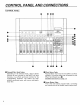
CONTROL PANEL AND CONNECTIONS Channel/Effect Send Waders Depending on the selected mode. these 8 fades function as-Revel controls for the DUMP s 8 input channels, or as effect send revel contrails forth Corresponding channels, The fades are predictability motorized types.. with a sure, solid operational feel.
@ COMP Key The DMD's internal stereo compressor is accessed and programmed using this key [Detailed instructions on page 23] @ PAN/PHASE Key. This key accesses both the panning and phase reversal functions for the currently selected input channel.
Note: The emphasis ON/OFF status applies to all DUMP channels simultaneously — independent detection of emphasis QON/OFF channels is not performed. When ON, DE-smphasis will be applied to the signal appearing at the analog outputs {MONITOR QUT, PHONES), and per-emphasized data will be output as is via the digital outputs. Iris therefore important to ensure that per-emphasis is hither ON or OFF for all channels of data received by the DUMP.
11 Although the DUMP is a "digital mixer” dealing entirely with digital signals, its basic signal flow and functional layout should be quite familiar 10 anyone who has worked with even simple audio mixing equipment. One aspect of the DUMP which may be surprising, however, is its apparent lack of external control hardware (EQ controls, separate effect send controls, etc.) in relation to the number of functions it provides.
13 SECTION 1: GENERAL OPERATION THE FADES CHANNEL ON KEYS in terms of external appearance and operation, the DMP70 fades are exactly the same as those on any other mixer. There are, however, two significant differences: 1) the fades are motorized, and 2} they have more than one function. Because the fades are motorized, they may feel slightly “heavier” than conventional types during manual operation. This, however, dis not affect mixing precision or performance.
15 EQUALIZATION / The DUMP offers a versatile 3-band parametric EQ system on sate channel. The Hi and LOW bands can be set to function as either peaking or shelving filters, while the MID band is always peaking type. In the peaking mode, all bands permit Q adjustment over a wide 0.1—5 range, permitting precise adjustment of a specific range of frequencies, SETTING EQ € Press SELECT key on channel for which adjusted.
17 Selected effect lap CHATTER, SEND sense BENDS e J@ SETTING THE RETURN LEVEL FROM THE SELECTED EFFECT © With the desired effect loop selected (SEND press the RETURN channel ON key to turn its LED not already ON) @ Set the RETURN fared to the desired level. * This process must be carried out independently for each effect loop. As you switch from effect loop to effect loop (e.g. from SEND 1 to SEND 2, etc.
5. FLANGE A 6. FLANGE B W8 sect | MOD DOTH | LRy Modulation Frequency (MOD FREQ): {Trey Sets the speed of modulation, and hence the rate at which the effect varies. Modulation Depth (MOD DEPTH: 0% —100% Sets the amount of delay time variation, thus adjusting the depth of the effect. At the maximum setting, the delay time is varied by =4 sec. Modulation Defy (MOD DIDDLY: 0.1 ms—100 ms This sets the basic delay time from the initial direct sound to the beginning of the flange effect.
21 17. STEREO ECHO 981 direct SIGNAL (TIME) e D RD Left Chan net Delay {LD}: 0.1 700 milliseconds After the delay set by this parameter, the first left channel echo will appear. Subsequent echoes will appear at the same time interval, the number of echoes depending on the setting of the feedback gain setting for the corresponding channel.
23 The DMD's digital stereo compressor permits compressing the overall stereo program to any desired degrees, limiting dynamic range, tor example, prior fo recording the program on type. 5 COMP OFF : . RATIO 0% RATIO 25% 5 “RATIO Ratio 75% Q _20 ey by i RATIO 100% 2% 75 o INPUT {aB] SETTING THE COMPRESSOR @ Press the COMP key. @ Use the PARAMETER keys or DATA ENTRY slider to turn the compressor ON or OFF. € Use the PARAMETER I> key to move the cursor to the “RATIO" parameter.
28 B2 © MEMORY PROTECT PROTECT ON 5 e MEMORY PROTECT % PROTECT OFF | * Please note that there is also a MEMORY PROTECT switch on RAM cartridge that must be turned OFF if you wish to store data to a cartridge memory location. MEMORY STORE This function is used to store the scene (all parameters) currently set up on the DUMP. Memory protect must be OFF prior to using the store function.
27 INITIALIZING NEW CARTRIDGES Yamaha RAM. cartridges must be initialized by the Beforehand they can be used with the DPT! @ Make sure a new Yamaha RAMA cartridge (or an old one which you don’t mind erasing} is properly inserted into the cartridge slot, and that the cartridge’s memory protect switch is OFF. @Press UTILITY key a few times to call RAM CARTRIDGE INITIALIZE function (the RAM CARTRIDGE INITIALIZE function will NOT appear if a RAM cartridge is not installed).
29 AUTO/MANUAL The AUTO/MANUAL key makes it possible to override external MIDI fared control so that fared positions may be changed manually while receiving MIDI data. This facilitates making "on-the-fly”’ modifications to a mixing program being received from a MIDI sequencer or similar device. Refer to the "MIDI CONTROL" section for details on MID! contra. @ Press the AUTO/MANUAL key to select either the AUTO or MANUAL mode.
31 MEMORY LOAVES } PAGE B MIDI SALVADOREAN PAGE v ‘MOI SAVE [ passe MEMORY SAVE, MEMORY LOAD MIDI SAVE, MIDI LOAD * The word “‘EXECUTE’" will appear on the bottom line of the LCD while the SAVE or LOAD operation is in progress. When completed, “END’" will appear. DIGITAL PAD Thus utility function allows setting between 0 dB and -24 dB attenuation for the 8 input channels and the EFFECT RETURN L/R inputs in 0.5 dB increments.
SCALDING / 2 or more DMP?Ds can be ‘‘cascaded”’ to provide additional input channels feeding a master stereo output buss. Cascading between DUMP units is fully digital, so no signal degradation occurs due to cascading. The CASCADE OUT terminal of the first DMP70 in the cascade chain is connected to the CASCADE IN terminal of the nextDMP?D, and so on.
35 SECTION 2: MIDI CONTROL MIDI SCENE CHANGES it is possible 1o change DUMP scenes {select different memory locations) remotely under MIDI contort. MID controlled scene changes are effected by sending an appropriate MIDI PROGRAM CHANGE NUMBER to the DUMP MID IN terminal {for more detailed information on MID) and the MIDI data categories, see Yamaha's “'THE MIDI Any MIDI device that can transmit, or record and re transmit MIDI program change numbers can be used to change scenes on the DUMP.
37 AL-TIME MIDI CONTROL Real time contra of all DUMP parameters can be carried out remotely via MIDI, using MIDI CONTROL CHANGE and NOTE NUMBER data {for more detailed information on MID and the MID data categories, see Yamaha's *‘THE MIDI BOOK""}. Each DUMP parameter has a parameter number (see DUMP PARAMETER CHART, below), and these may be individually assigned to any MIDI control change number or note on number.
39 ! NOTE ASSIGN CONTROL ASSIGN 8 PRM=255| |GNTL= 0 PRM=205 INNOVATE LN NOTE ASSIGN NOTE=1271 PRM=25% NOTE ASSIGN * The initial factory-programmed program change, note an number and control change number assign meets can be restored by tuning the DPT OFF, then turning the power back ON while holding both the FARED FLIP and MIDI keys, (See AL DATA CHAD CAUTION!! Do not try other power-on key combinations. Software failure may scour.
4t { EDITING RECORDED MIDI / SEQUENCE DATA . The method of recording real-time MID) control data to a sequencer directly from the DUMP has already been described in the "REAL-TIME MIDI CONTROL"’ section on page 37. Three functions are provided in the UTILITY group which allow editing a section of an already-recorded mix down sequence: 1. FARED EDIT CHANNEL ASSIGN 2. PAN POT EDIT CHANNEL ASSIGN 3.
IMPORTANT NOTICE FOR THE UNITED KINGDOM Connecting the Plug and Cord WARNING : THIS APPARATUS MUST BE EARTHED IMPORTANT. The wires in this mains lead are colored in accordance with the following code: GREEN-AND-YELLOW .
SECTION 5: CONNECTOR COMPATIBILITY The DUMP has the following four types of output connector: 1. DIGITAL OUT (Sony format, RS-422 level, XLR type connector) 2. DIGITAL OUT {Sony format, TTL level, BNG connector). QUT (AESCHYLUS SECT format, 0.5 V €, pin jack) 4. AESCHYLUS OUT (AESCHYLUS SECT format, RS-422 Revel, XLR type connector). The following is a fist of equipment which can currently be connected to the DMP70 cutouts.
139 # PCM PROCESSORS TEMPT Model Connector Recorder Connector Connection Cable Sony DIGITAL VO ENC IN connector . POM-1810 2 (BNC. TTL) BNG BNG cable. Sony DIGITAL KO ENC iN connector POM-1630 2 @Ne, TIL) BNC BNG cable, o PROFESSIONAL DATA RECORDER Model o Recorder Connector Connection Carla connector Sony . DIGITAL IN connector POM-2000 (AESCHYLUS, XLR types, 3V-10V) XLR XLR cable. Sony . AESCHYLUS IN connector PM-2500 XLH type, RE-422) LR XLR cable. * A patch bay is recommended for smooth system setup.
189 / SPECIFICATIONS General Total Harmonic Distortion Frequency Response Dynamic Range Hum & Noise {stairs out) Maximum Voltage Gain (Digital) Lass than 0.
168 SECTION 8: RACK-MOUNTING AND DATA CHARTS RACK-MOUNTING THE DUMP DIMENSIONS The Distemper supplied with a rack-mounting kit which allows it to be mounted in any standard 19" Emilia 348 equipment rack. To rack-mount the DMP70, follow the steps given below: 800 000600 B @ Remove the left and right side-bracket of the DUMP by first removing the four screws that hold each O 000= 00O bracket.
* SEND 3 EFFECTS 169 No. | Program Nam. ’ . Parameter WeH 1..| STEED EGO 1700 ms 80 % 1750 ms~175.0 ms 0 % 0.1 ms~ 1750 ms %91~ x 10 MO0 FREE 0D DEARTH MOD LY 7 B GAN 2 |FLANGE 25t 50 % gizmos 35 % 01 H~200 Hr D%~ 100 1000 ms % MO REG CHORUS 200 Bz 4%~ 100 % G %~ 100 % MO0 FREQ. MO0 DRIFT WOD LY 4 | PHASING 11t 100 200 He 0 %100 % 01ms~b58 ms MOBBED. MO0 DOTH § | PAN POT Hr~20.0 e D%~ 100 EXTERNAL LEQ 100 800 215 8 0150 external mea 10 ki w08 07 o T 250 ¥~ 8.0 kil 01-50 EXTERNAL HEQ 10.
8 Waw 98 WOd Waw £ WBd wan 8ZL WBd wan S8 WOd waw ¢ Wod WIN 421 WOd waw 8 WOd WaW it WDd w Wan 9zL Wod wIn EB HOd Wil o WDd WIW $2t Nod W3 Z8 WOd wan 6¢ WOd waw 2L WO ww In 18 Wod waw 8E WHd WIW TZL WOd waw 08 WDd Wil L8 WOd ww Iw 2ZL WSd wan 6L WD waw 98 Wod wan 1Z1 Wad wan 8L WDd WAN € Wod w Win WOd waW 8Lk WDd waw 8L W04 wIN €% Wod wan 8LE WOd www ¢ Wod waw 28 Wod waw 1L WOd WIW vL Wod wAN L8 WOd WiN 9Ll AOd W £L WD waw 0 wod WIN it WO wIn 2L wod wam 62 Wod WaN Y WOd wan it WOd WiN 82 WOd W3 €Lt WOd Waw