Thank you for purchasing the Yamaha P2700/P2350 Power Amplifier. The P2700/P2350 is a high-output power amplifier which is highly stable, very reliable, and housed in a compact, lightweight body. The P2700/P2350 features a full course of Yamaha technology. For example, a 2-speed autocratic-switching double fan and a double straight heat sink enable continuous operation at high power levels.
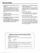
PRECAUTIONS 1. Avoid Excessive Heat, Humidity, Dust and Vibration Keep the unit away from locations where it is likely to be exposed to high temperatures or humidity — such as near radiators, stoves, eic. Also avoid location which are subject to excessive dust accumulation or vibration which could cause mechanical damage. Avoid Physical Shocks Strong physical shocks to the nit can cause damage. Handle it with care.
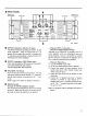
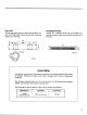
OPERATION B FRONT PANEL Handle o 9 T Handle YAMAHA 7 © PROTECTION Indicator The PROTECTION indicator lights for approximately 6 seconds after the POWER switch is pressed to indicate that the protection circuitry is aerating. No sound is output from the speakers while this indicator is 1it.
W REAR PANEL Screws for rear support Cord reel ] Screws for Cord reel rear support @ INPUT Connectors (XOR-3-31 type) The INPUT connectors are balanced, XOR-3-31 type input connectors, They are wired with Pin 1 as ground, Pin 2 as signal hot, and Pin 3 as signal cold, As connectors, they conform to Cannon XLR-3-12C Witchcraft 5C-1055A standards. INPUT Connectors (TRS Phone type) These balanced TRS connectors accept balanced and unbalanced input signals. Tip=hot, Springfield, Sleeve=ground.
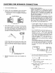
RACK MOUNTING When the amplifier is mounted in a rack, the heat generated by the amplifier heats up the air inside the rack causing the temperature of the amplifier’s operating environment to increase. It is therefore necessary for the rack to be well ventilated in order to lower the temperature of the air surrounding the amplifier. Since hot air inside the rack will tend to rise to the top, the most effective ventilation method is to draw air in at the bottom of the rack and expel it from the top.
Fan Unit The fan unit shown uses two fans, each maximum volume of 29 CFM {(cubic feet per minute) and a maxima pressure of 5 mm H20. 480 18 248 unit: mm Ventilated Panel Yamaha VP1 ventilation panel may be provided as an optional accessory (open area should be at least 35% of total area), CAUTION! If unit(s) are to be used in a rack mounted installation, it is recommended that fan cooling be installed. Without fan cooling, units could be damaged from excessive temperature conditions.
M Portable Rack Mounting 1. Rules for mounting in portable racks (road cases) are basically the same as for when less than five amplifiers are mounted in a single rack. However, when mounting a power amplifier in a case made for housing only one amplifier, mount a blank panel (ventilated) below the amplifier and make ventilation holes (with a numerical aperture of 0.
CAUTION FOR SPEAKER CONNECTION 4. Turn off the POWER switch. Remove the cover attachment screws and remove the protective covers from the speaker terminals. * The protective covers are equipped with general model only. Cover attachment scows After removing approx.
SPECIFICATIONS P2700 P2350 POWER OUTPUT LEVEL STEREO: 350W « 350W; AL = 8 ohms, kHz, THD 5 6.1 % 500W + S00W; AL = 4 tums, kHz, THD £0.1 % AMONG: 1000W; Rl = 8 ohms, kHz, THD £0.1 % STEREO: 175W + 175W; RL = 8 ohms, kHz, THD s 0.1 % 250W + 250W. RL = 4 ohms, kHz, THD 5 0.1 % MONO: S00W; AL = 8 ohms, kHz, THD 201 % FREQUENCY RESPONSE 098 +0.5, -t 5dB: kHz, RL = 8 ohms, Po= { W POWER BANDWIDTH STEED: kHz; Po = 175 ohms, THD kHz; Po = 280 ohms, THD = 0.1 % MONO: kHz: Po = 500 ohms, THD = 0.
Parody P2350 INDICATORS POWER Hed LED; turns on when Power is On PROTECTION Red LED; tums an when protection or muting is On CLIPPING Red LED; wns on when THD 2 1% SIGNAL Goren LED; wens on when Si gnat output above 2 Vr.mus., (means 1 W. 4 ohms) kHz} PROTECTION CIRCUITS OUTPUT MUTING 6 sec. & 2 sec.: after power is on DC sense DG £2 V: output shut off THERMAL 2100 degrees eat sink temp. LIMITER RL 5 2 ohms Fan curtail FAN HI-SPEED: 70 deg. C. (heat sink temp.) FAN LO-SPEED; 60 deg. C.
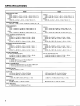
TROUBLESHOOTING The following table lists the main causes of abnormal operation and the corrective measures required, as well as the protective circuit operation in each case. Indicator display Probable cause Remedy Protective circuit operation CLIP indicator lights. ‘There is a short at a speaker terminal, amplifier terminal, or wire. Locate end correct the cause of the short, The PC limiter circuit operates fo protect the power transistors, The amplifier load is excessive.
DIMENSIONS 437 (173167} 6 301 (1178 6 36 57 371 ey 21 G wine)] @iEY @18y @167y 1 {3ii67y l 1 noon 11 sey T 8 Penney | S 102 wane 435 132 (5:3167) [UEE[0 O 652 ] 33603127 1118 T@nns” @16 480 (18-78") Anne Unit: mm {inch)