DIGITAL-MISCHPULT D
Wichtige Hinweise i Wichtige Hinweise Bitte lesen Sie sich folgende Hinweise durch, bevor Sie sich mit dem 02R an die Arbeit machen. Vorsichtsmaßnahmen Aufstellung des 02R • Verbinden Sie das 02R ausschließlich mit einer Steckdose, die die auf dem Typenschild und in der Bedienungsanleitung erwähnte Netzspannung führt. • Schützen Sie das 02R vor Feuchtigkeit. Lassen Sie keine Flüssigkeiten in das Geräteinnere gelangen. Lassen Sie es niemals im Regen oder Schnee stehen.
ii Wichtige Hinweise • Stellen Sie das 02R niemals an einen extrem heißen Ort, lassen Sie es niemals in einem in der prallen Sonne stehenden Auto liegen und stellen Sie es nicht in die Sonne. • Stellen Sie das 02R niemals an extrem staubige oder feuchte Orte. Auch dann entsteht nämlich Brandgefahr. • Schließen Sie das Stromkabel niemals mit feuchten Händen an die Netzsteckdose an. Sonst bekommen Sie nämlich einen Stromschlag.
Wichtige Hinweise iii • Stellen Sie die Lautstärke aller Geräte auf den Mindestwert, bevor Sie sie Ihre Anlage einschalten. Übertriebene Lautstärkepegel sind dem Gehör nämlich eher abträglich. • Wenn Sie das 02R längere Zeit nicht verwenden möchten (wenn Sie in Urlaub fahren, zum Beispiel), ziehen Sie am besten den Netzstecker, um auf Nummer sicher zu gehen. Wenn das 02R während des Betriebes nicht erwartungsgemäß funktioniert, ziehen Sie am besten sofort den Netzstecker.
iv Wichtige Hinweise Wenn Sie den Eindruck haben, daß die Fader nicht mehr erwartungsgemäß reagieren, lesen Sie bitte Seite 198 der Bedienungsanleitung zum Kalibrieren der Fader. Externe Datensicherung Die im 02R gespeicherten Daten könnten bei einer Fehlfunktion bzw. einer Reparatur verlorengehen. Daher raten wir Ihnen, alle wichtigen Daten jeweils via MIDI extern zu sichern.
Wichtige Hinweise v Warenzeichen ADAT und Alesis sind eingetragene Warenzeichen der Alesis Corporation. ADAT Multichannel Optical Digital Interface ist ein Warenzeichen der Alesis Corporation. TEAC® ist ein eingetragenes Warenzeichen der TEAC CORPORATION. Tascam Digital Audio Interface (TDIF-1™) ist ein Warenzeichen der TEAC CORPORATION. Alle anderen erwähnten Warenzeichen sind eingetragene Warenzeichen der jeweiligen Eigentümer. Lieferumfang Zum Lieferumfang des 02R gehören folgende Gegenstände.
vi Wichtige Hinweise Digital-Mischpult 02R Kurzanleitung
Bedienungsanleitung DIGITAL-MISCHPULT Bedienungsanleitung
Inhaltsverzeichnis i Inhaltsverzeichnis 1 Vorstellung des 02R. . . . . . . . . . . . . . . . . . . . . . . . . . . . 1 Digital-Mischpult 02R . . . . . . . . . . . . . . . . . . . . . . . . . . . . . . . . . . . . . . . . . 2 Bedienungsanleitung . . . . . . . . . . . . . . . . . . . . . . . . . . . . . . . . . . . . . . . . . . 3 Aufstellung . . . . . . . . . . . . . . . . . . . . . . . . . . . . . . . . . . . . . . . . . . . . . . . . . . 4 Bedienoberfläche und Rückseite . . . . . . . . . . . . . . . . .
ii Inhaltsverzeichnis 5 Mischen und automatisieren . . . . . . . . . . . . . . . . . . . 63 Wie funktioniert die Automation des 02R? . . . . . . . . . . . . . . . . . . . . . . 64 Echtzeit-Automation . . . . . . . . . . . . . . . . . . . . . . . . . . . . . . . . . . . . . . . . . 65 Editieren der Automix-Ereignisse . . . . . . . . . . . . . . . . . . . . . . . . . . . . . . 73 Die Feinarbeit . . . . . . . . . . . . . . . . . . . . . . . . . . . . . . . . . . . . . . . . . . . . . . .
Vorstellung des 02R 1 1 Vorstellung des 02R In diesem Kapitel finden Sie... 1 Digital-Mischpult 02R . . . . . . . . . . . . . . . . . . . . . . . . . . . . . . . . . . . . . . . . . . . . 2 Bedienungsanleitung . . . . . . . . . . . . . . . . . . . . . . . . . . . . . . . . . . . . . . . . . . . . 3 Aufstellung . . . . . . . . . . . . . . . . . . . . . . . . . . . . . . . . . . . . . . . . . . . . . . . . . . . . . 4 Bedienoberfläche und Rückseite . . . . . . . . . . . . . . . . . . . . . . . . . . . .
2 Vorstellung des 02R Digital-Mischpult 02R Das 02R wird von der Firma gebaut, die das erste Digital-Mischpult vorgestellt und sich seither mit ihrer DSP-Technologie einen Namen gemacht hat. Das 02R ist das vielseitigste Digital-Mischpult der Welt.
Vorstellung des 02R 3 RISC-Technologie Das 02R wird von einem RISC-Prozessor gesteuert, der eine so umfassende Bedienung und Automation überhaupt erste möglich macht. Dank dieser Leistungsstärke verdient das 02R den Rang des wichtigsten Audioteils in Ihrer Anlage allemal. Bedienungsanleitung Dem 02R liegt eine Bedienungsanleitung bei, die aus zwei Teilen besteht: dieser Kurzanleitung und der Bedienungsanleitung.
4 Vorstellung des 02R Aufstellung Stellen Sie das Digital-Mischpult 02R immer auf eine stabile Oberfläche, und zwar am besten so, daß das Display gut ablesbar ist und daß Sie alle Regler mühelos bedienen können. Hinter dem 02R lassen Sie am besten so viel wie möglich Freiraum, damit das Anschließen der Signalquellen und anderen Geräte problemlos verläuft. Nur so kann man nämlich professionell in einem Digital-Studio arbeiten.
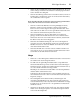
Vorstellung des 02R 5 Bedienoberfläche und Rückseite +48V +48V +48V +48V +48V +48V +48V ON ON ON ON ON ON OFF OFF OFF OFF OFF OFF OFF A B A B 20dB +4 -16 +48V ON A B 20dB -40 +4 -16 GAIN -60 A B 20dB -40 +4 -16 GAIN -60 A B 20dB -40 +4 -16 GAIN -60 A B 20dB -40 GAIN -60 +4 -16 -40 +4 -16 OFF A B 20dB GAIN -60 ON A B 20dB -40 +4 -16 GAIN -60 0 -40 +4 -16 GAIN -60 20dB -40 +4 -16 GAIN -60 -40 PEAK PEAK PEAK PEAK PEAK PEAK PEAK PEAK
6 Vorstellung des 02R Features Eckdaten des 02R • A/D-Wandler: 20 Bit linear und 64fachem Oversampling • D/A-Wandler: 20 Bit linear und 8fachem Oversampling • Dynamikumfang: 105dB (typisch) • Interne Datenverarbeitung im 32Bit-Format mit einem Dynamikumfang von mehr als 190dB dank eines von Yamaha entwickelten 32bitDSP-Chips Allgemeine Features Digital-Mischpult 02R • 40 Eingangskanäle mit Dynamikprozessor und 4-Bandentzerrung.
Vorstellung des 02R 7 • 8 Analoge Einschleif-/Ausgangsanschlüsse • 2 analoge 2TR IN-Anschlüsse • 2 analoge Stereo-Ausgänge • 6 analoge AUX SEND-Anschlüsse • Stereo-Ausgänge für die Studio- und Regieabhöre • 3 digitale 2TR IN-Anschlüsse • Digitale Ein- und Ausgänge mit den gängigen Formaten (AES/EBU oder IEC958 part2) • Motorisierte 100mm-Fader • Fader und Mute-Gruppen, damit mit einem Fader oder Taster der Pegel mehrere Kanäle eingestellt werden kann bzw.
8 Vorstellung des 02R Wichtigste Merkmale In diesem Kapitel wollen wir uns die herausragenden Funktionen des 02R einmal aus nächster Nähe ansehen, damit Sie begreifen, wozu sie dienen. Dynamische Automation Eine der wichtigsten Aufgaben eines Toningenieurs ist die Kombination aller aufgezeichneten Signale zu einer befriedigenden Abmischung.
Vorstellung des 02R 9 Das Aufrufen einer Szene ist sogar noch einfacher: drücken Sie den [RECALL]-Taster. Bei soviel Flexibilität muß man natürlich auch den warnenden Zeigefinger erheben: Da alles blitzschnell geht, sollten Sie immer etwa gleichartige Szenen hintereinander verwenden, da es sonst zu drastischen Pegelsprüngen kommen kann. Anmerkung: Allerdings ist auch das kein alle zu großes Problem, da man auf dem 02R auch die Pegelübergänge von einer Szene zur nächsten programmieren kann.
10 Vorstellung des 02R TING-Feld können Sie den angewählten Kanal einer Summe zuordnen. Mit dem AUX-Feld bestimmen Sie den Effektanteil sowie die Effektzuordnung des angewählten Kanals. Mit dem PAN-Feld können Sie die Stereoposition des angewählten Kanals einstellen. Im EQ-Feld schließlich läßt sich die Klangregelung des angewählten Kanals einstellen. Das 02R kann übrigen so programmiert werden, daß beim Betätigen einer Funktion dieser Felder automatisch die dazugehörige Display-Funktion aufgerufen wird.
Vorstellung des 02R 11 Dynamikprozessoren Dynamikprozessoren werden in der Regel zum Korrigieren oder Bändigen von Signalpegeln verwendet. Man kann sie jedoch auch kreativ einsetzen, um z. B. die Amplitudenhüllkurve der angebotenen Signale zu ändern. Das 02R bietet sehr umfassende Dynamikprozessoren, die den Eingangskanälen, Bandrückwegen und den Stereo-Ausgangskanälen zugeordnet werden können – insgesamt stehen 50 Dynamikprozessoren zur Verfügung.
12 Vorstellung des 02R Ein Digital-Pult addiert und subtrahiert lediglich Zahlenwerte. Die vom 02R für diese Berechnungen verwendeten 32bit DSP-Chips (Digital Signal Processors) arbeiten so genau, daß es kaum je zu Rechenfehlern kommt. Wenn ein Signal also erst einmal durch den A/D-Wandler gelangt ist, kann es nicht mehr zu Signalbeeinträchtigungen kommen. Rauschen, mangelnde Kanaltrennung und Frequenzgruppenverzögerungen sind also völlig ausgeschlossen.
Und los geht’s 2 13 Und los geht’s In diesem Kapitel finden Sie... Ausgangspunkt . . . . . . . . . . . . . . . . . . . . . . . . . . . . . . . . . . . . . . . . . . . . . . . . 14 Anschließen . . . . . . . . . . . . . . . . . . . . . . . . . . . . . . . . . . . . . . . . . . . . . . . . . . . 14 Grundeinstellungen . . . . . . . . . . . . . . . . . . . . . . . . . . . . . . . . . . . . . . . . . . . . 15 Ein- und Ausschalten . . . . . . . . . . . . . . . . . . . . . . . . . . . . . . . . . . . . . . . .
14 Und los geht’s Ausgangspunkt Das Digital-Mischpult 02R eignet sich vor allem als Mischpult für Studios, in denen modulare Mehrspurmaschinen (mit Magnetbändern oder Festplatten) der jüngsten Generation verwendet werden. Obwohl man es auch in Beschallungsanlagen verwenden könnte, besitzt der typische Anwender wohl eher ein kleines Ton- oder Nachbearbeitungsstudio, in dem eine Mehrspurmaschine verwendet wird.
Und los geht’s ACHTUNG! Schließen Sie das 02R ausschließlich an eine Netzsteckdose mit der erforderlichen Spannung an. Siehe das Typenschild. 15 Außerdem könnten Sie den Stereo-Masterrecorder mit der digital- oder den analogen STEREO OUT-Buchsen verbinden. 4. Verbinden Sie das 02R mit einer geeigneten Netzsteckdose. Grundeinstellungen Bitte entnehmen Sie alle notwendigen Anschlüsse nachstehender Zeichnung.
16 Und los geht’s Ein- und Ausschalten In diesem Kapitel zeigen wir Ihnen, wie man das 02R ein- und ausschaltet. Einschalten POWER ON/ OFF Schalten Sie Ihre Anlage immer in der hier angegebenen Reihenfolge ein: Signalquelle, 02R, Endstufe. Drücken Sie den POWER-Schalter auf der Rückseite, um das 02R einzuschalten. Nun erscheint die Begrüßungsanzeige, die Fader werden initialisiert und das Display zeigt die Seite an, die vor dem Ausschalten angewählt wurde.
Einführung 3 17 Einführung In diesem Kapitel finden Sie... Einpegeln der Signale . . . . . . . . . . . . . . . . . . . . . . . . . . . . . . . . . . . . . . . . . . . 18 Entzerrung (Verwendung des Equalizers). . . . . . . . . . . . . . . . . . . . . . . . . . 22 Einsatz der Equalizer-Bibliothek . . . . . . . . . . . . . . . . . . . . . . . . . . . . . . . . . . 28 Signalweg . . . . . . . . . . . . . . . . . . . . . . . . . . . . . . . . . . . . . . . . . . . . . . . . . . . . .
18 Einführung Einpegeln der Signale Gehen wir einfach davon aus, daß das Digital-Mischpult 02R bereits eingeschaltet ist und daß Ihre Signalquelle etwas abspielt. Bevor es richtig losgeht, müssen Sie erst einmal die Abhöre einstellen, und eine vorläufige Abmischung erstellen. Am besten rufen Sie also den Szenenspeicher “0 – Initial Data” auf, weil dann alle Fader in die 0dB-Position fahren (gleicher Pegel für alle Kanäle).
Einführung 19 Einstellen des Eingangspegels (GAIN) und der Meter 1. Drücken Sie den [METER]-Taster. METER Im Display erscheint nun die METER-Funktion, die auch gleich den Signalpegel des MIC/LINE 1-Anschlusses anzeigt. 2. Drücken Sie den [SEL]-Taster des MIC/LINE 1-Kanals. SEL 20dB Nun ist Eingangskanal MIC/LINE 1 hörbar. 3.
20 Einführung Verringern Sie also den GAIN-Wert, bis die PEAK-Diode nur noch bei Pegelspitzen leuchtet. Den GAIN-Regler muß man auch wieder mit Bedacht einstellen: Zu geringe Werte beeinträchtigen den Fremdspannungsabstand (Rauschen), während zu hohe Werte zu Verzerrung führen. ∅/ATT Display-Funktion Es kann auch vorkommen, daß der Signalpegel im Digital-Bereich noch zu hoch ist.
Einführung 21 2. Wahrscheinlich können Sie die Peak Hold-Funktion hier gut gebrauchen. Um sie einzuschalten, wählen Sie mit den CURSOR-Tastern die PEAK HOLD-Ikone an. Drücken Sie anschließend [ENTER]. Wenn die Peak Hold-Funktion eingeschaltet ist, wird die Ikone hell auf dunklem Hintergrund abgebildet. Die Pegelspitzen werden mit Hilfe eines hohlen Kästchens angezeigt. Peak Hold (Pegelspitzenhaltefunktion) ist besonders hilfreich bei der optischen Überwachung während der Aufnahme und Wiedergabe.
22 Einführung Das SCENE MEMORY-Display Das 7segmentige LED-Display (2 Zeichenpositionen) informiert Sie jeweils über den derzeit aktiven Szenenspeicher. Es enthält außerdem eine Diode, die zu blinken beginnt, sobald Sie auch nur einen Parameterwert ändern. Weitere Einzelheiten entnehmen Sie bitte dem Kapitel "Szenenspeicher" auf Seite 58. SCENE MEMORY Editierikone Entzerrung (Verwendung des Equalizers) Nach dem Einpegeln können Sie das an MIC/LINE 1 anliegende Signal entzerren.
Einführung 23 Auch im weiteren Verlauf dieser Einführung konzentrieren wir uns auf die Display-Funktionen. Allerdings raten wir Ihnen, bei der “wirklichen” Arbeit immer den direktesten Weg zu wählen. Ein- und ausschalten der Entzerrung 1. Drücken Sie den [SEL]-Taster des MIC/LINE 1-Kanals. SEL Wenn Sie den [SEL]-Taster eines Kanals drücken, leuchten alle notwendigen Dioden der SELECTED CHANNEL-Tastengruppe, um den Status des angewählten Kanals anzuzeigen. 2. Drücken Sie den [EQ]-Taster.
24 Einführung Anhebung/Absenkung 1. Wählen Sie die G-Ikone (Anhebung/Absenkung) des LOW-Frequenzbandes mit den CURSOR-Tastern. Diese Ikone wird nun von einem blinkenden grauen Kästchen umgeben, um anzuzeigen, daß dieser Parameter aktiviert ist. Sie könnten allerdings auch den [LOW/HPF]-Taster im SELECTED CHANNEL-EQUALIZERFeld drücken. 2. Drehen Sie das Dateneingaberad im Uhrzeigersinn, um den Pegel dieses Frequenzbandes anzuheben.
Einführung 25 Das Frequenzband kann man auch mit den [L-MID], [H-MID] und [HIGH/LPF]-Tastern des SELECTED CHANNEL – EQUALIZER-Feldes anwählen. Anmerkung: Wenn ein Frequenzband zu stark angehoben wird, kann der sich daraus ergebende Signalpegel zu Übersteuerung führen. Wenn das bei Ihnen der Fall ist, verringern Sie entweder den Pegel des betreffenden Frequenzbandes oder die Einstellung des ATT-Parameters (Abschwächung).
26 Einführung Anmerkung: Die Zentralfrequenz des gewählten Bandes wird sowohl als numerischer Wert (z.B. 1.0K) in der Grafik und im LED-Display des SELECTED CHANNEL-EQUALIZER-Feldes, als auch mit Hilfe einer Strichlinie in der Kurvengrafik angezeigt. 3. Wählen Sie mit den CURSOR-Tastern die F-Ikone des L-MID-Bandes an und ordnen Sie diesem Band mit dem Dateneingaberad die gewünschte Frequenz zu. Tun Sie dies auch für die verbleibenden Bänder.
Einführung 27 3. Drehen Sie das Dateneingaberad gegen den Uhrzeigersinn, um die Güte (Q) des LOW-Bandes zu erhöhen. Dadurch wird die Bandbreite schmaler. Siehe nachstehende Abbildung. Eine schmale Bandbreite eignet sich zum Anheben oder Absenken einer ganz bestimmten Frequenz. 4. Wählen Sie mit den CURSOR-Tastern die Q-Ikone des L-MIDBandes und stellen Sie die gewünschte Güte mit dem Dateneingaberad ein. Tun Sie dies auch für die verbleibenden Frequenzbänder.
28 Einführung Einsatz der Equalizer-Bibliothek Die Equalizer-Bibliothek dient zum Speichern und Laden von EQ-Einstellungen, die als Programme archiviert werden. Es gibt 40 Werksprogramme (1~40) und 88 Anwenderprogramme (41~128 plus UNDO), in denen Sie Ihre eigenen Einstellungen unterbringen können. Zuerst wollen wir Ihnen zeigen, wie man ein EQ-Programm aufruft. Anschließend erfahren Sie, wie man ein Programm speichert. Laden eines EQ-Programms EQ 1. Drücken Sie den [EQ]-Taster.
Einführung 29 4. Wählen Sie mit dem Dateneingaberad das gewünschte EQ-Programm an. Beim Durchlauf der EQ-Programme erscheint rechts neben der Übersicht jeweils eine Zeichnung des Frequenzverhaltens des betreffenden Programms. 5. Drücken Sie den [ENTER]-Taster. Das vom Cursor angezeigte EQ-Programm wird nun geladen. Außerdem wird die Entzerrung des MIC/LINE 1-Kanals der geladenen Frequenzkurve entsprechend eingestellt. Auch die Kurvengrafik im obersten Feld zeigt die neue Entzerrungskurve an.
30 Einführung Sehen Sie sich die Einstellungen kurz an. Laden der EQ-Einstellungen rückgängig machen (Undo) Wenn Ihnen das geladene EQ-Programm beim näheren Hinhören doch nicht gefällt, können Sie die vorigen Einstellungen wieder aufrufen. 1. Wählen Sie mit den CURSOR-Tastern die RECALL-Ikone an und drehen Sie an dem Dateneingaberad, bis sich der Cursor auf dem “U”-Programm befindet. Das “U”-Programm ist eigentlich der Undo-Puffer.
Einführung 31 Die EQUALIZER LIB-Funktion erscheint nun wieder im Display, wobei die Grafik die gerade eingestellte Entzerrungskurve enthält. 2. Wählen Sie mit dem Dateneingaberad ein EQ-Programm an. Wenn Sie ein Werksprogramm (1~40) wählen, blinkt im Display eine Fehlermeldung, sobald Sie Ihre Einstellungen dort zu speichern versuchen. Ihre eigenen Einstellungen können ausschließlich in einem Anwenderspeicher (41~128) untergebracht werden.
32 Einführung Ein EQ-Programmname kann bis zu 16 Zeichen enthalten, darunter auch Punkte, Kommata usw. Mit der INS-Ikone können Sie an der von Cursor angezeigten Position eine Leerstelle einfügen. Wählen Sie die INS-Ikone mit den CURSORTastern an und drücken Sie [ENTER], um eine Leerstelle einzufügen. Die DEL-Ikone dient zum Löschen des vom Cursor angezeigten Zeichens.
Einführung 33 Wenn Sie die Einstellungen aber wohl speichern möchten, wählen Sie mit den CURSOR-Tastern die “EXECUTE”-Ikone an. Drücken Sie anschließend den [ENTER]-Taster. Das EQ-Programm wird dann gespeichert. Anmerkung: Wenn Ihnen das EQ-Programm doch nicht besonders gefällt, können Sie in dem betreffenden Speicher andere EQ-Einstellungen unterbringen. Andererseits ist es jedoch auch durchaus denkbar, daß Sie im Eifer des Gefechts ein wertvolles EQ-Programm überschreiben.
34 Einführung Auf dem 02R kann man die ersten 16 MIC/LINE-Kanäle direkt dem gewünschten Ausgang zuordnen. Wenn Sie über ein kompatibles System verfügen, können Sie also 16 Spuren verwenden (z.B. zwei modulare ADAT-Achtspurmaschinen). Außerdem können Sie jeden beliebigen Kanal an eine der acht Summen (Busse) anlegen. Diese Summen können ihrerseits dann zur Achtspurmaschine geleitet werden. Selbstverständlich kann jeder Kanalzug auch an die Stereo-Summe angelegt werden.
Einführung 35 Kanalzuordnung (Routing) 1. Drücken Sie den [ROUTING]-Taster. ROUTING Im Display erscheint nun die ROUTING-Funktion, die Sie über die Zuordnung des MIC/LINE 1-Kanals aufklärt. 2. Mit den ROUTING-Tastern der SELECTED CHANNEL-Gruppe können Sie die Zuordnung des MIC/LINE 1-Kanals nun ändern. Wenn Sie einen der ROUTING-Taster drücken, leuchtet die Diode dieses Tasters auf, während die dazugehörige Ikone auf der ROUTING-Seite hell auf dunklem Hintergrund abgebildet wird.
36 Einführung Schneller geht es aber mit den Tastern und Reglern des PAN-Feldes der SELECTED CHANNEL-Gruppe. L/ODD L ODD R/EVEN R EVEN PAN Anmerkung: Das 02R kann so programmiert werden, daß bei Verwendung eines Reglers oder Tasters im SELECTED CHANNEL-PAN-Feld automatisch die PAN Display-Funktion aufgerufen wird. Siehe “Preferences (Vorzüge)” auf Seite 190 in der Bedienungsanleitung.
Einführung 37 2. Drücken Sie den [SEL]-Taster des MIC/LINE 1-Kanals und drehen Sie am PAN-Regler. Die Diode des [L/ODD]-Tasters leuchtet nun. Die gegenwärtige Stereoposition wird mit Hilfe der danebenliegenden LED-Balkenkette angezeigt. Andererseits können Sie jedoch auch mit den CURSOR-Tastern die PAN-Ikone des MIC/LINE 1-Kanals anwählen und am Dateneingaberad drehen, bis der gewünschte Wert angezeigt wird.
38 Einführung Jede Änderung, die Sie nun für einen Kanal des Paares vornehmen, wird im gleichen Verhältnis auch beim anderen Kanal des Stereopaares durchgeführt. Weitere Einzelheiten entnehmen Sie bitte dem Kapitel “Panorama von Stereopaaren” auf Seite 39 in der Bedienungsanleitung.
Und der zweite Aufnahmestreich folgt sogleich… 4 39 Und der zweite Aufnahmestreich folgt sogleich… In diesem Kapitel finden Sie... Effekthinwege (AUX) . . . . . . . . . . . . . . . . . . . . . . . . . . . . . . . . . . . . . . . . . . . 40 Einstellen des Effekthinwegpegels . . . . . . . . . . . . . . . . . . . . . . . . . . . . . . . . 41 Kontrollabmischung (Monitor Submix) . . . . . . . . . . . . . . . . . . . . . . . . . . . . 42 Effekte verwenden. . . . . . . . . . . . . . . . . . . . . . . . . . .
40 Und der zweite Aufnahmestreich folgt sogleich… Effekthinwege (AUX) Das Digital-Mischpult 02R ist mit acht Effektwegen ausgestattet. AUX7 und AUX8 sind an die internen Effektprozessoren angelegt, was also bedeutet, daß diese beiden Signale die Digital-Ebene zu keiner Zeit verlassen. Die anderen Effekthinwege hingegen –AUX1~AUX6– erlauben das Einschleifen von externen Effekten, die Verwendung von Kontrollverstärkern sowie weiteren Mehrspurmaschinen.
Und der zweite Aufnahmestreich folgt sogleich… 41 Einstellen des Effekthinwegpegels Im nachfolgenden Beispiel zeigen wir Ihnen, wie man den Pegel von MIC/LINE 1 für den AUX1-Weg einstellt (damit wird dann die Effektintensität bestimmt). 1. Drücken Sie den [AUX 1]-Taster. AUX 1 FADER STATUS INPUT AUX 1 2 3 4 5 6 7 8 Im Display erscheint nun die AUX1-Funktion. Wie bereits erwähnt, dienen die Kanalfader nun zum Einstellen des Effekthinwegpegels.
42 Und der zweite Aufnahmestreich folgt sogleich… 4. Um den Pegel zu ändern, müssen Sie den Fader des MIC/LINE 1-Kanals anders einstellen, bis dieser Kanal ausreichend Effekt bekommt. Um den Effekthinwegpegel der Bandrückwege einzustellen, müssen Sie die Drehregler verwenden (die Effektrückwege können nur mit den Drehpotis eingestellt werden). Ist das zu umständlich, drücken Sie kurzerhand [FLIP], um die Kanalfader den Bandrückwegen zuzuordnen.
Und der zweite Aufnahmestreich folgt sogleich… 43 4. Stellen Sie den Pegel des MIC/LINE 1-Kanals mit dessen Fader ein. Mit der Kommandofunktion (Talkback) können Sie die Musiker fragen, ob es ihnen so genehm ist. Wenn die Kontrollabmischung eingestellt ist, drücken Sie den [ST]-Taster im CONTROL ROOM-Feld, um das Control Room-Signal abzuhören. Effekte verwenden Das 02R bietet zwei interne Effektprozessoren, Effect1 und Effect2, die an die Summen AUX7 und AUX8 angelegt sind. Den Ausgangspegel (d.h.
44 Und der zweite Aufnahmestreich folgt sogleich… Die Fader zeigen nun die Effekthinwegpegelwerte an. Auch hier gilt, daß das nicht bedeutet, daß die Signale bestimmter Kanäle dadurch unhörbar werden, weil das 02R die Kanalpegelwerte zeitweilig gespeichert hat. 2. Wählen Sie den MIC/LINE 1-Kanal mit dessen [SEL]-Taster oder den CURSOR-Tastern. Ordnen Sie diesen Kanal nun den AUX-Wegen zu, indem Sie zuerst den [AUX7] und anschließend den [ON]-Taster im SELECTED CHANNELAUX-Feld drücken. 3.
Und der zweite Aufnahmestreich folgt sogleich… 45 2. Wenn das Signal verzerrt und sich der Pegel fortwährend im CLIP-Bereich bewegt, wählen Sie mit den CURSOR-Tastern die ∅/ATT-Ikone an. Stellen Sie den Pegel anschließend mit dem Dateneingaberad ein. Da es sich hier um ein Digital-Signal handelt, ist im CLIP-Bereich auftretende Verzerrung äußerst unangenehm. Anmerkung: In der Regel rührt Übersteuerung des Effektrückwegs von einem übertriebenen Effekthinwegpegel her.
46 Und der zweite Aufnahmestreich folgt sogleich… Effekte aufrufen und editieren Nach dem Anlegen des MIC/LINE 1-Kanals an einen Effekthinweg möchten Sie natürlich wissen, wie man einen Effekt aufruft, dessen Parameter editiert und die Änderungen dann speichert. Effektprogramme aufrufen 1. Drücken Sie den [AUX 7]-Taster, bis die EFFECT Display-Funktion (Editierseite) erscheint. AUX 7 EFF1 Im Display werden nun die Parameter des derzeit aktiven Effekts angezeigt.
Und der zweite Aufnahmestreich folgt sogleich… 47 3. Wählen Sie mit den CURSOR-Tastern die RECALL-Ikone an. Verwenden Sie zur Anwahl des gewünschten Effektprogramms das Dateneingaberad. Der Cursor gleitet nun über die Effektnamen, wobei jeweils der Name des Effektprogramms auf dunklem Hintergrund erscheint, das Sie durch Drücken des [ENTER]-Tasters aufrufen können. 4. Drücken Sie den [ENTER]-Taster. Das betreffende Effektprogramm wird nun geladen.
48 Und der zweite Aufnahmestreich folgt sogleich… Ändern Sie nicht zuviele Parameter auf einmal und hören Sie sich das Ergebnis sorgfältig an. Manche Parameteränderungen haben kaum Hörbare Folgen, während andere überaus drastisch sind. Wenn alle Effektparameter stimmen, können Sie sie in einem Effektprogramm speichern. Effektprogramme speichern Das 02R bietet 88 Speicher, in denen Sie eigene Effektprogramme unterbringen können (41~128).
Und der zweite Aufnahmestreich folgt sogleich… 49 2. Wählen Sie mit den CURSOR-Tastern das TITLE EDIT-Fenster. 3. Mit den CURSOR-Tastern können Sie zu der gewünschten Zeichenposition fahren, der Sie dann mit dem Dateneingaberad ein Zeichen zuordnen. Ein Effektprogrammname kann bis zu 16 Zeichen enthalten, darunter auch Punkte, Kommata usw. Mit der INS-Ikone können Sie an der vom Cursor angezeigten Position eine Leerstelle einfügen.
50 Und der zweite Aufnahmestreich folgt sogleich… Wenn Sie eines der Werksprogramme (1~40) wählen, blinkt im Display eine Fehlermeldung, sobald Sie Ihre Einstellungen dort zu speichern versuchen. Ihre eigenen Einstellungen können ausschließlich in einem Anwenderspeicher (41~128) untergebracht werden. Außerdem können Sie selbst nichts im Undo-Puffer speichern (das geht nur automatisch). 5. Drücken Sie den [ENTER]-Taster.
Und der zweite Aufnahmestreich folgt sogleich… 51 Anwendung der Dynamikprozessoren Das 02R ist mit einer eindruckvollen Anzahl Dynamikprozessoren ausgestattet: Jeder Eingangskanal, Bandrückweg, die Stereo-Ausgänge sowie die Summenausgänge können mit einem Dynamikeffekt bearbeitet werden. Über diese Dynamikprozessoren haben Sie Zugriff auf Kompressoren, Expander, Compander (Kompressor mit Expander), Gates und eine Ducking-Funktion (automatische Pegelreduzierung).
52 Und der zweite Aufnahmestreich folgt sogleich… Gesang sinnvoll ist (weil z.B. das Rauschen des Verstärkers nicht aufgenommen wird). Ducking wird oft für Kommentare verwendet, und zwar damit die Hintergrundmusik leiser wird, sobald der Kommentar einsetzt. Im Grunde ist Ducking auch ein Kompressor, der jedoch von einer anderen Signalquelle gesteuert wird. Kompressor für das Stereo-Signal Die Dynamikeffekte kann man natürlich für die angebotenen Signale verwenden – z.B.
Und der zweite Aufnahmestreich folgt sogleich… 53 3. Wählen Sie mit den CURSOR-Tastern die DYNAMICS OFF-Ikone an und drücken Sie den [ENTER]-Taster, um den Prozessor einzuschalten. Die DYNAMICS-Ikone erscheint nun auf dunklem Hintergrund und statt OFF wird ON angezeigt. Dank der Möglichkeit, den Dynamikprozessor schnell ein- und auszuschalten, können Sie A/B-Vergleiche (mit und ohne Dynamikeffekt) anstellen. 4.
54 Und der zweite Aufnahmestreich folgt sogleich… Einsatz der Dynamikbibliothek Als nächstes wollen wir Ihnen zeigen, wie man ein Dynamikprogramm der Bibliothek aufruft und seine eigenen Dynamikeinstellungen in einem Programm speichert. Aufrufen eines Dynamikprogramms 1. Drücken Sie den [DYNAMICS]-Taster noch einmal. DYNAMICS Im Display erscheint nun die DYNAMICS Library-Seite. Andererseits könnten Sie mit den CURSOR-Tastern die LIB-Ikone anwählen und den [ENTER]-Taster drücken. 2.
Und der zweite Aufnahmestreich folgt sogleich… 55 Editieren eines Dynamikprogramms Auch die Dynamikprogramme können editiert und dann in einem Anwenderspeicher untergebracht werden. Das Digital-Mischpult 02R bietet 40 Werksdynamikprogramme (1~40).
56 Und der zweite Aufnahmestreich folgt sogleich… Speichern eines Dynamikprogramms Das 02R bietet 88 Anwenderspeicher für Dynamikprogramme (41~128). Auch hier gilt, daß man die Dynamikeinstellungen entweder in einem Programm speichern oder einfach in einem Szenenspeicher unterbringen kann. Im folgenden zeigen wir Ihnen, wie man die Dynamikeinstellungen in einem Dynamikprogramm speichert. 1. Drücken Sie den [DYNAMICS]-Taster noch einmal. Im Display erscheint nun die DYNAMICS Library-Seite.
Und der zweite Aufnahmestreich folgt sogleich… 57 Mit der INS-Ikone können Sie an der von Cursor angezeigten Position eine Leerstelle einfügen. Wählen Sie die INS-Ikone mit den CURSORTastern an und drücken Sie [ENTER], um eine Leerstelle einzufügen. Die DEL-Ikone dient zum Löschen des vom Cursor angezeigten Zeichens. Anmerkung: Mit den COPY- und PASTE-Ikonen können Sie den Namen eines bestehenden Dynamikprogramms kopieren und in das TITLE EDIT-Feld einsetzen.
58 Und der zweite Aufnahmestreich folgt sogleich… Szenenspeicher Das Digital-Mischpult 02R bietet auch Szenenspeicher, in denen Sie jeweils einen Schnappschuß aller Digital-Einstellungen speichern können. Insgesamt stehen 64 Szenenspeicher zur Verfügung. Jedem Szenenspeicher können Sie übrigens einen Namen geben. Es gibt zwei besondere Szenenspeicher. “0 – Initial Data” ist ein Speicher, dessen Daten nur gelesen (also nicht überschrieben) werden können.
Und der zweite Aufnahmestreich folgt sogleich… 59 CANCEL ist bereits angewählt. Wenn Sie den Speichervorgang abbrechen möchten, drücken Sie also jetzt den [ENTER]-Taster. Andernfalls warten Sie 10 Sekunden, bis das 02R die Speicherfunktion selbsttätig deaktiviert. Wenn Sie die Einstellungen aber wohl speichern möchten, wählen Sie mit den CURSOR-Tastern die “EXECUTE”-Ikone an. Drücken Sie anschließend den [ENTER]-Taster. 3. Die Mischszene wird dann gespeichert.
60 Und der zweite Aufnahmestreich folgt sogleich… Um ganz sicherzugehen, daß auch wirklich die richtigen Einstellungen gespeichert werden, sollten Sie sie noch kurz kontrollieren, bevor Sie fortfahren. Siehe "Aufrufen eines Szenenspeichers" auf Seite 60. 3. Wählen Sie mit den CURSOR-Tastern das TITLE EDIT-Feld an. 4. Mit den CURSOR-Tastern können Sie zu der gewünschten Zeichenposition fahren, der Sie dann mit dem Dateneingaberad ein Zeichen zuordnen.
Und der zweite Aufnahmestreich folgt sogleich… 61 1. Wählen Sie den gewünschten Szenenspeicher mit den SCENE MEMORY ▲/▼ Tastern an. Wenn Sie einen Szenenspeicher wählen, der noch keine Daten enthält, blinkt dessen Nummer im SCENE MEMORY-Display. 2. Drücken Sie den [RECALL]-Taster. Die gewählte Mischszene wird nun geladen. Anmerkung: Bitte bedenken Sie, daß die Anwahl eines anderen Szenenspeichers auch Pegeländerungen nach sich ziehen kann, weil z.B. Signalquellen zugeschaltet werden.
62 Und der zweite Aufnahmestreich folgt sogleich… Digital-Mischpult 02R Kurzanleitung
Mischen und automatisieren 5 63 Mischen und automatisieren In diesem Kapitel finden Sie... Wie funktioniert die Automation des 02R? . . . . . . . . . . . . . . . . . . . . . . . . . 64 Echtzeit-Automation . . . . . . . . . . . . . . . . . . . . . . . . . . . . . . . . . . . . . . . . . . . . 65 Editieren der Automix-Ereignisse . . . . . . . . . . . . . . . . . . . . . . . . . . . . . . . . . 73 Die Feinarbeit . . . . . . . . . . . . . . . . . . . . . . . . . . . . . . . . . . . . . . . . . . . . . . .
64 Mischen und automatisieren Wie funktioniert die Automation des 02R? Beim Erstellen einer Mehrspuraufnahme unterscheidet man 3 wichtige Etappen: • Anschließen der Signalquellen und Aufzeichnen der ersten Spuren • Überspielen (Hinzufügen weiterer Parts) • Abmischung Zwar hat jede Etappe einen besonderen Stellenwert, aber die Abmischung ist bestimmt der schwierigste und langwierigste Schritt. Die Musiker sind zu dem Zeitpunkt nämlich schon fertig.
Mischen und automatisieren 65 Echtzeit-Automation In diesem Buch gehen wir davon aus, daß Sie das Digital-Mischpult 02R mit einer oder mehreren E/A-Platinen verwenden. Im folgenden zeigen wir Ihnen, wie man das 02R mit einer Mehrspurmaschine synchronisiert. Das geht auf drei Arten: • Wenn Ihre Mehrspurmaschine über einen SMPTE-Ausgang verfügt, können Sie ihn mit einem Audiokabel mit dem SMPTE TIME CODE INPUT-Anschluß des 02R verbinden.
66 Mischen und automatisieren 3. Verwenden Sie die CURSOR-Taster zur Anwahl der Frame-Auflösung und drücken Sie [ENTER]. Das 02R unterstützt folgende genormte Frame-Auflösungen: • 30 — 30 Frames pro Sekunde (Frame= Bild). • 30D — 29.97 Frames pro Sekunde (30 Drop Frame). • 25 — 25 Frames pro Sekunde. • 24 — 24 Frames pro Sekunde. Die hier eingestellt Frame-Auflösung gilt für alle drei Zeitcodetypen: SMPTE, MTC und intern. 4.
Mischen und automatisieren 67 Erstellen eines neuen Automix Bevor die Einstellungen des 02R aufgezeichnet werden können, müssen Sie erst einmal eine neue Automix-Session starten. Dabei wird der Inhalt des gegenwärtigen Automix’ (d.h. alle Ereignisse) gelöscht, weil wieder die Werkseinstellungen geladen werden. Wenn Sie den Inhalt des gegenwärtigen Automix’ aber noch brauchen, sollten Sie ihn speichern, bevor Sie weitermachen. 1. Drücken Sie den [AUTOMIX]-Taster noch einmal.
68 Mischen und automatisieren 4. Wählen Sie mit den CURSOR-Tastern die “NEW”-Ikone an und drücken Sie den [ENTER]-Taster. Im Display erscheint nun eine Rückfrage, die Sie bestätigen müssen, wenn Sie tatsächlich einen neuen Automix erstellen möchten. Dieses Rückfragefenster bietet zwei Ikonen: “CANCEL” und “EXECUTE”. CANCEL ist bereits angewählt. Wenn Sie den NEW-Befehl also doch nicht ausführen möchten, drücken Sie den [ENTER]-Taster – oder Sie warten ganz einfach 10 Sekunden.
Mischen und automatisieren 69 Aufzeichnen der ersten Session 1. Drücken Sie mehrmals den [AUTOMIX]-Taster, um die “Automix Main”-Seite aufzurufen. AUTOMIX Sobald die “Automix Main”-Seite angezeigt wird, brauchen Sie den [AUTOMIX]-Taster nicht mehr zu drücken: 2. Wählen Sie mit den CURSOR-Tastern die “RECORD”-Ikone und drücken Sie den [ENTER]-Taster. Die “RECORD”-Ikone blinkt, um anzuzeigen, daß das 02R aufnahmebereit ist. 3.
70 Mischen und automatisieren Wenn das 02R im Aufnahmebereitschaftsbetrieb einen Zeitcode empfängt, beginnt die “REC”-Ikone zu leuchten und erscheint auf dunklem Hintergrund. Der empfangene Zeitcode wird im “Time Code”-Feld der “Automix Main”-Seite abgezeigt.
Mischen und automatisieren 71 Anmerkungen zur Mischautomation • Zum Ändern der Panorama- oder Entzerrungseinstellungen ist es vielleicht einfacher, die Taster und Regler der SELECTED CHANNEL-Gruppe zu verwenden. • Wenn Sie mehrere Kanäle Kanal aufnahmebereit gemacht haben ([SEL]-Taster), ist die SELECTED CHANNEL-Gruppe jeweils dem zuletzt angewählten Kanal zugeordnet. Das gleich gilt auch für die Anwendung der Entzerrung und der Dynamikprozessoren.
72 Mischen und automatisieren Wie eben bereits erwähnt, kann man einen Automix-Durchgang auch rückgängig machen, indem man mit den CURSOR-Tastern die “UNDO”Ikone anwählt und [ENTER] drückt. In der Regel kann man kleine Ausrutscher durch Ein- und Aussteigen wieder ausbügeln. 7. Halten Sie den Zeittaktgeber an.
Mischen und automatisieren 73 Editieren der Automix-Ereignisse Ereignisse überschreiben Bereits aufgezeichnete Ereignisse kann man überschreiben. Das bedeutet im Klartext, daß man die aufgezeichneten Ereignisse eines Kanals durch neue ersetzen oder Ereignisse für einen anderen Kanal aufzeichnen kann. Vielleicht haben Sie zuerst die Fader-Einstellungen der Rhythmussektion aufgezeichnet und möchten anschließend die Einstellungen der Sologitarre und des Gesangs aufzeichnen. 1.
74 Mischen und automatisieren den Einstellungen bereits zu Beginn der Automix-Aufzeichnung gelöscht. 5. Starten Sie den Zeittaktgeber. Selbstverständlich haben Sie ihn in der Zwischenzeit zurückgespult, damit er wieder von vorne beginnt. Alle bereits aufgezeichneten Ereignisse werden nun wiedergegeben. 6. Hören Sie sich die vorläufige Abmischung an und ändern Sie die Einstellungen, die überschrieben werden sollen. 7.
Mischen und automatisieren 75 5. Hören Sie sich die Abmischung an und drücken Sie den [SEL]Taster des korrekturbedürftigen Kanals an der Stelle, wo Sie einsteigen möchten. Die Aufzeichnung beginnt nun just ab der Stelle. Anmerkung: Von hier ab werden die zuvor aufgezeichneten Ereignisse gelöscht und durch die neuen ersetzt. 6. Nehmen Sie alle notwendigen Änderungen vor, während Sie sich die Abmischung anhören. 7.
76 Mischen und automatisieren Editieren der Fader- und Reglereinstellungen Wenn Sie nicht unbedingt einsteigen möchten, können Sie bestimmte Fader- und Reglereinstellungen einzeln editieren, indem Sie die “Fader Edit”-Seite aufrufen. 1. Wenn nötig, drücken Sie mehrmals den [AUTOMIX]-Taster, um die “Automix Main”-Seite aufzurufen. AUTOMIX 2. Wählen Sie mit den CURSOR-Tastern die “FADER - Overwrite”Ikone an drücken Sie den [ENTER]-Taster. 3. Drücken Sie mehrmals den [AUTOMIX]-Taster.
Mischen und automatisieren 77 Das 02R befindet sich nun im Aufnahmebereitschaftsbetrieb. 7. Hören Sie sich die Abmischung an und drücken Sie den [SEL]Taster des benötigten Kanals, sobald Sie eine Einstellung korrigieren möchten. Die Aufnahme beginnt an der Stelle, wo Sie den [SEL]-Taster drücken. 8. Ändern Sie die Fader-Einstellung des aktivierten Kanals. Hier werden nun sowohl die ursprüngliche als die neue Fader-Position angezeigt.
78 Mischen und automatisieren Die Feinarbeit Editieren der Szenenspeicher- und Programmanwahl Die Anwahlereignisse, mit denen Szenenspeicher und Programme aufgerufen werden, können zeitlich versetzt werden. 1. Drücken Sie mehrmals den [AUTOMIX]-Taster. AUTOMIX Sobald die “Event Edit (MEMORY)”-Seite erscheint, brauchen Sie diesen Taster nicht mehr zu drücken. Hier wird eine Liste von Zeitwerten angezeigt.
Mischen und automatisieren • • 79 CH.Lib. –Anwahl eines Kanalprogramms. Die Zahl bezieht sich auf den angewählten Speicher der Kanalbibliothek (1~64). Channel – Der Kanal, auf den sich die Änderung bezieht. Die Anwahl eines Szenenspeichers gilt selbstverständlich für alle Kanäle (kein Eintrag). 3. Ändern Sie den vom Cursor angezeigten Wert mit dem Dateneingaberad. Im Falle des Zeitcodes können Sie die Stunden, Minuten, Sekunden und Frames einstellen. 4.
80 Mischen und automatisieren Hier wird eine Liste von Zeitcodeeintragungen angezeigt. Des weiteren erfahren Sie, auf welchen Kanal sich die Ereignisse jeweils beziehen und ob der betreffende Kanal zu- oder abgeschaltet wird. Außerdem sind zwei Ikonen belegt: DELETE (löschen) und INSERT (einfügen). 2. Wählen Sie mit den CURSOR-Tastern das zu editierende Ereignis an. Mit den CURSOR-Tastern können Sie die Ereignisse der Reihe nach abklappern.
Mischen und automatisieren 81 Ereignisse löschen Aufgezeichnete Ereignisse können entweder einzeln (DELETE) oder in einem bestimmten Bereich (EXTRACT) gelöscht werden. Für letztere Funktion können dann ein Zeitcodebereich, die gewünschten Kanäle sowie der Ereignistyp gewählt werden. 1. Drücken Sie noch einmal den [AUTOMIX]-Taster. AUTOMIX Sobald die “Event Extract”-Seite erscheint, brauchen Sie diesen Taster nicht mehr zu drücken. 2.
82 Mischen und automatisieren Wählen Sie mit den CURSOR-Tastern “ONE”, wenn nur der angewählte Kanal eingeschaltet werden soll. Wählen Sie “ALL”, wenn Sie alle Kanäle aktivieren möchten. Drücken Sie den [ENTER]-Taster, um Ihre Wahl zu bestätigen. 4. Wählen Sie nun die zu löschenden “Parameters” mit den CURSOR-Tastern und drücken Sie jeweils den [ENTER]-Taster, um den angezeigten Parameter zu aktivieren oder zu deaktivieren.
Mischen und automatisieren 83 Die gewählten Ereignisse werden nun entfernt – und zwar im Bereich zwischen dem “In Time”- und dem “Out Time”-Wert. 8. Wenn Sie plötzlich Heimweh nach den soeben gelöschten Ereignissen bekommen, führen Sie den Cursor zur “UNDO”Ikone und drücken den [ENTER]-Taster, um die gerade gelöschten Ereignisse wiederherzustellen. 9.
84 Mischen und automatisieren Einsatz der Automix-Bibliothek Speichern eines Automix’ Das 02R bietet 16 Speicher (1~16), in denen Sie Ihre Mischprogramme unterbringen können. Sehen wir uns einmal an, wie man ein AutomixProgramm speichert: 1. Drücken Sie den [AUTOMIX]-Taster, bis die “Memory Management”-Seite angezeigt wird: AUTOMIX 2. Wählen Sie mit den CURSOR-Tastern das TITLE EDIT-Feld an. 3.
Mischen und automatisieren 85 Mit der INS-Ikone können Sie an der vom Cursor angezeigten Position eine Leerstelle einfügen. Wählen Sie die INS-Ikone mit den CURSORTastern an und drücken Sie [ENTER], um eine Leerstelle einzufügen. Die DEL-Ikone dient zum Löschen des vom Cursor angezeigten Zeichens. Anmerkung: Mit den COPY- und PASTE-Ikonen können Sie den Namen eines bestehenden Automix-Programms kopieren und in das TITLE EDIT-Feld einsetzen.
86 Mischen und automatisieren Aufrufen eines Automix-Programms 1. Drücken Sie den [AUTOMIX]-Taster, bis die “Memory Management”-Seite angezeigt wird: AUTOMIX 2. Wählen Sie mit den CURSOR-Tastern die RECALL-Ikone an. Verwenden Sie das Dateneingaberad für die Anwahl des zu ladenden Programms. Hier wird wieder eine ganze Liste angezeigt, wobei immer das Programm geladen werden kann, das der Cursor gerade anzeigt. Wenn Sie das gewünschte Programm gefunden haben, drücken Sie den [ENTER]Taster. 3.
Kurzanleitung DIGITAL-MISCHPULT Kurzanleitung
Kapitelübersicht i Kapitelübersicht 1 Anschlüsse und Bedienfeld . . . . . . . . . . . . . . . . . . . . . 1 2 Benutzeroberfläche. . . . . . . . . . . . . . . . . . . . . . . . . . . 17 3 Abmischen und abhören . . . . . . . . . . . . . . . . . . . . . . 25 4 MIXING Display-Funktionen . . . . . . . . . . . . . . . . . . . . 33 5 Dynamik . . . . . . . . . . . . . . . . . . . . . . . . . . . . . . . . . . . . 65 6 Effektkanäle (AUX) . . . . . . . . . . . . . . . . . . . . . . . . . . .
ii Kapitelübersicht Digital-Mischpult 02R Bedienungsanleitung
Die Kapitel im einzelnen iii Die Kapitel im einzelnen 1 Anschlüsse und Bedienfeld . . . . . . . . . . . . . . . . . . . . . 1 Bedienfeld . . . . . . . . . . . . . . . . . . . . . . . . . . . . . . . . . . . . . . . . . . . . . . . . . . . 2 Rückseite . . . . . . . . . . . . . . . . . . . . . . . . . . . . . . . . . . . . . . . . . . . . . . . . . . . 11 Blockschaltbild . . . . . . . . . . . . . . . . . . . . . . . . . . . . . . . . . . . . . . . . . . . . . . 16 2 Benutzeroberfläche. . . . . . . . . .
iv Die Kapitel im einzelnen Routing. . . . . . . . . . . . . . . . . . . . . . . . . . . . . . . . . . . . . . . . . . . . . . . . . . . . . 41 ROUTING-Taster . . . . . . . . . . . . . . . . . . . . . . . . . . . . . . . . . . . . . . . . . . . . 43 Meter (optische Signalüberwachung) . . . . . . . . . . . . . . . . . . . . . . . . . . . 44 View . . . . . . . . . . . . . . . . . . . . . . . . . . . . . . . . . . . . . . . . . . . . . . . . . . . . . . . 47 Kanalbibliothek . . . . . . . . . . . . . . . . . .
Die Kapitel im einzelnen v Werkseffektprogramme. . . . . . . . . . . . . . . . . . . . . . . . . . . . . . . . . . . . . . 104 8 Szenenspeicher . . . . . . . . . . . . . . . . . . . . . . . . . . . . . 123 Was genau sind Szenenspeicher?. . . . . . . . . . . . . . . . . . . . . . . . . . . . . . 124 Was wird in den Mischszenen gespeichert?. . . . . . . . . . . . . . . . . . . . . 125 Sagten Sie Editierpuffer? . . . . . . . . . . . . . . . . . . . . . . . . . . . . . . . . . . . . .
vi Die Kapitel im einzelnen 12 Digital-Eingänge, -Einstellungen und Zusatzfunktionen . . . . . . . . . . . . . . . . . . . . . . . . 181 Word Clock Select (Zeittakt) . . . . . . . . . . . . . . . . . . . . . . . . . . . . . . . . . 182 Anwahl des Eingangssignals (Input Signal Select) . . . . . . . . . . . . . . 185 Cascade Configuration . . . . . . . . . . . . . . . . . . . . . . . . . . . . . . . . . . . . . . 186 Dither . . . . . . . . . . . . . . . . . . . . . . . . . . . . . . . . . . . . . . . . . .
Anschlüsse und Bedienfeld 1 1 Anschlüsse und Bedienfeld In diesem Kapitel finden Sie... 1 Bedienfeld . . . . . . . . . . . . . . . . . . . . . . . . . . . . . . . . . . . . . . . . . . . . . . . . . . . . . . 2 Rückseite . . . . . . . . . . . . . . . . . . . . . . . . . . . . . . . . . . . . . . . . . . . . . . . . . . . . . . 11 Blockschaltbild . . . . . . . . . . . . . . . . . . . . . . . . . . . . . . . . . . . . . . . . . . . . . . . . .
2 Anschlüsse und Bedienfeld Bedienfeld SELECTED CHANNEL-Gruppe Bedienelemente der Analog-Eingänge Bedienelemente der Analog-Ausgänge Display und dazugehörige Bedienelemente DISPLAY ACCESS-Gruppe Abhörtastenwahlfeld SCENE MEMORY-Bedienfe Zum Display gehörige Bedienelemente Fader Digital-Mischpult 02R Bedienungsanleitung
Anschlüsse und Bedienfeld 3 Bedienfeld der Analog-Eingänge +48V +48V 1 2 +48V ON ON ON OFF OFF OFF A B A B A B 3 20dB 20dB 20dB 4 +4 -16 5 6 -40 GAIN -60 +4 -16 -40 GAIN -60 +4 -16 -40 GAIN -60 PEAK PEAK PEAK SIGNAL SIGNAL SIGNAL 1 2 3 1 Taster für die Phantomspeisung (Kanal 1~8) Mit diesen Tastern können Sie die +48 Gleichstromphantomspeisung der XLR-3-31-Anschlüsse ein- und ausschalten.
4 Anschlüsse und Bedienfeld Bedienfeld der Analog-Ausgänge 0 10 T/B LEVEL 1 1 T/B LEVEL-Regler und Mikrofon Mit diesem Regler bestimmen Sie die Lautstärke des eingebauten Kommandomikrofons. 2 PHONES LEVEL-Regler und -Anschluß 2 0 10 STUDIO LEVEL 0 10 Mit dem Regler bestimmen Sie die Lautstärke im Kopfhörer, den Sie zu Abhörzwecken an die dazugehörige Buchse angeschlossen haben.
Anschlüsse und Bedienfeld 5 2 MIXING-Taster Mit den Tastern in diesem Feld haben Sie Zugriff auf die dazugehörigen Display-Funktionen. Taster Beschreibung ∅/ATT Einstellen der Phase und der Digital-Abschwächung. DELAY Einstellen der Kanalverzögerung. PAN Einstellen der Stereoposition. ROUTING Einstellen des Signalwegs. METER Optische Überwachung der einzelnen Eingangskanäle, der Band- und Effektrückwege, der 8 Hauptsummen (Busse) und der acht Effektsummen (AUX).
6 Anschlüsse und Bedienfeld Display, Anzeigen und Regler 1 4 5 Editierikone SCENE MEMORY CLIP -2 -4 -6 FADER STATUS INPUT -12 -15 -24 2 AUX 1 2 3 4 5 6 7 8 -35 -48 -60 -72 SELECTED CHANNEL L STEREO R 3 MIC/LINE CONTRAST TAPE/RTN OUTPUT 6 1 SCENE MEMORY-Anzeige In diesem LED-Display (2 Zeichen, 7 Segmente) erscheint jeweils die Nummer der angewählten Mischszene. Außerdem enthält diese Anzeige ein Diode, die zu blinken beginnt, sobald Sie auch nur einen Parameterwert ändern.
Anschlüsse und Bedienfeld 7 SELECTED CHANNEL-Gruppe SELECTED CHANNEL 1 1 2 AUX 1 AUX 2 3 4 AUX 3 AUX 4 5 6 AUX 5 AUX 6 7 8 AUX 7 EFF1 AUX 8 EFF2 ST DIRECT SEND LEVEL ROUTING L/ODD 2 ON AUX L ODD R/EVEN 3 R EVEN PAN Q LOW/HPF L-MID H-MID HIGH/LPF F Hz kHz 4 G dB EQ ON EQUALIZER 1 ROUTING-Taster Mit diesen Tastern stellen Sie den Signalweg des aktiven Kanals ein. 2 AUX-Taster und -Regler Mit den Tastern und Reglern dieses Feldes wählen Sie den Effektweg (AUX1~8).
8 Anschlüsse und Bedienfeld Abhörsignal 1 STUDIO-Tastenfeld C-R ST AUX 5 AUX 6 Mit diesen Tastern wählen Sie das Signal, das an die STUDIO MONITOR OUTPUT-Buchsen angelegt wird. 1 2 CONTROL ROOM-Tastenfeld STUDIO Mit diesen Tastern wählen Sie das Signal, das an die C-R MONITOR OUT-Buchsen angelegt wird.
Anschlüsse und Bedienfeld 9 Fader 4 1 1 2 SEL 3 SEL SEL SEL SEL ON ON ON TAPE TAPE TAPE 14 15 16 SEL SEL SEL SEL SEL SEL SEL SEL ON ON ON ON ON ON ON ON FLIP ON ON EFF1 RTN EFF2 RTN 2 3 10 10 10 10 10 10 10 0 15 15 15 15 15 15 15 30 20 20 20 20 20 20 20 30 30 30 30 30 30 30 40 40 40 40 40 40 40 50 50 50 50 50 50 50 ∞ ∞ ∞ ∞ ∞ ∞ ∞ 40 50 14 15 16 17/18 19/20 21/22 60 70 ∞ 23/24 STEREO 5 1 TAPE-Regler (Bandr
10 Anschlüsse und Bedienfeld 4 FLIP-Taster Mit diesem Taster bestimmen Sie, welches Eingangssignal mit den Fadern usw. bedient werden kann (MIC/LINE1~16 bzw. TAPE RETURN 1~16). Dann brauchen Sie den Pegel der Bandrückwege nicht mehr mit dem TAPE-Regler (siehe S. 9) einzustellen. 5 Fader Mit diesen motorisierten 100mm-Fadern können Sie den Pegel des betreffenden Kanals einstellen.
Anschlüsse und Bedienfeld 11 Display-Bedienfeld 5 CURSOR-Taster Mit diesen Tastern können Sie einen im Display angezeigten Parameter bzw. eine Funktion anwählen. 6 Dateneingaberad Mit diesem Rad können Sie den Wert des angewählten Parameters einstellen. Drehen Sie das Rad im Uhrzeigersinn, um den Wert zu erhöhen bzw. gegen den Uhrzeigersinn, um den Wert zu verringern.
12 Anschlüsse und Bedienfeld 2 AUX SEND-Buchsen Hierbei handelt es sich um asymmetrische 1/4”-Klinkenbuchsen mit einem Nennausgangspegel von +4dB. Hier liegt das Signal der Effekthinwege AUX1~6 an, so daß Sie diese Buchsen mit den Eingängen der Außenbordeffekte, Kontrollverstärker oder Mehrspurmaschinen verbinden können. 3 C-R MONITOR OUT-Buchsen Hierbei handelt es sich um symmetrische 1/4”-Klinkenbuchsen mit einem Nennausgangspegel von +4dB. Die Bedrahtung lautet TRS.
Anschlüsse und Bedienfeld 13 8 Eingangskanäle (1~8) Die INPUT A (1~ 8) Buchsen sind als symmetrische XLR-3-31Anschlüsse ausgeführt, deren Nenneingangspegel –60dB~+4dB beträgt. Die Bedrahtung entspricht der IEC 268-Norm: Stift 1– Masse, Stift 2–heiß (+) und Stift 3–kalt (–). Außerdem kann hier die Phantomspeisung für Kondensatormikrofon angelegt werden (siehe S. 3). Anmerkung: Bitte schauen Sie immer erst nach, ob die hier angeschlossenen Geräte folgendermaßen bedrahtet sind: 2= heiß, 3= kalt.
14 Anschlüsse und Bedienfeld Der AES/EBU-Ausgang ist als XLR-3-32 Buchse ausgeführt. Hier liegt das gleiche Signal an wie an der vorigen Buchse, allerdings diesmal im IEC958 Part 3 (AES/EBU - Professional) Format. C MIDI-Buchsen Dies sind genormte 5stiftige MIDI-Buchsen (THRU, OUT und IN). Verbinden Sie diese Buchsen mit einem MIDI-Sequenzer, wenn Sie Wert legen auf eine MIDI-Steuerung beider Geräte.
Anschlüsse und Bedienfeld 15 G Steckplätze für optionale Platinen (1~4) In diese Steckplätze können optionale E/A-Platinen geschoben werden. Verfügbare Platinen Platine Format Name AES/EBU CD8-AE Digital-E/A Größe Steckplatz Doppelt 1 ~ 2 (max. 2 Platinen= 16 Kanäle) CD8-AE-S Einfach 1 ~ 4 (max. 4 Platinen= 32 Kanäle) ADAT optisch CD8-AT Einfach 1 ~ 4 (max. 4 Platinen= 32 Kanäle) TDIF-1 CD8-TDII Einfach 1 ~ 4 (max. 4 Platinen= 32 Kanäle) Yamaha CD8-Y Einfach 1 ~ 4 (max.
INSERT I/O +0dB INPUT B INPUT 18,20 22,24 INPUT 17,19 21,23 INPUT 9-16 1-8 INPUT A B A ON +48V OFF HA GAIN HA GAIN HA HA GAIN 20dB PAD 20dB PAD (+48V) DC CUT DC CUT SIGNAL PEAK DC CUT EFF1,2 DC CUT SIGNAL PEAK A/D A/D A/D A/D SIGNAL PEAK PHASE 4BAND EQ 4BAND EQ 4BAND EQ 4BAND EQ 4BAND EQ 2TR IN ANALOG R L 3 2 L 2 –10dBV R 1 +4dB COAXIAL AES/EBU 1 PHASE PHASE PHASE 2TR IN DIGITAL ATT ATT PHASE Same as 1-8 ATT DYNAMICS OSC Meter DELAY HA T/B LE
Benutzeroberfläche 2 17 Benutzeroberfläche In diesem Kapitel finden Sie... Ein Wort zur Benutzeroberfläche . . . . . . . . . . . . . . . . . . . . . . . . . . . . . . . . . 18 DISPLAY ACCESS-Taster . . . . . . . . . . . . . . . . . . . . . . . . . . . . . . . . . . . . . . . . 18 Display . . . . . . . . . . . . . . . . . . . . . . . . . . . . . . . . . . . . . . . . . . . . . . . . . . . . . . . 20 CURSOR-Taster . . . . . . . . . . . . . . . . . . . . . . . . . . . . . . . . . . . . . . . . . . . . . .
18 Benutzeroberfläche Ein Wort zur Benutzeroberfläche Die Benutzeroberfläche des 02R ist zwar sehr umfassend, aber trotzdem sehr leicht zu bedienen. Mit dem 02R kann man nämlich auf zwei Arten arbeiten: • Mit den Bedienelementen der DISPLAY ACCESS-Gruppe. In diesem Fall kann jeweils ein Parameter des Pultes eingestellt werden. • Mit den Bedienelementen des SELECTED CHANNEL-Feldes, mit dem Sie Zugriff haben auf alle Parameter des aktiven Kanals. Diese Bedienelemente erinnern stark an ein Analog-Pult.
Benutzeroberfläche 19 • Mit dem [DIGITAL I/O]-Taster haben Sie Zugriff auf die DigitalParameter: Synchronisation (Word Clock), Anwahl des 02R über die Digital-Ein- und -ausgangsbuchsen, Einstellen der Cascade-Konfiguration und Word Dither. • Der [SETUP]-Taster bietet Zugriff auf die SOLO-Parameter und die Systemvorzüge (Preferences). • Mit dem [UTILITY]-Taster können Sie die Oszillatorfunktion einstellen sowie die Batteriespannung, Emphasis-Einstellung und den Kanalstatus kontrollieren.
20 Benutzeroberfläche AUX-Feld AUX 1 AUX 2 AUX 5 AUX 6 AUX 3 AUX 4 AUX 7 EFF1 AUX 8 EFF2 AUX Mit diesem Taster haben Sie Zugriff auf die Display-Funktionen, mit denen Sie den Effekthinwegpegel einstellen können. • Mit [AUX 1]~[AUX 6] wählen Sie den betreffenden Effektweg. Außerdem können Sie hier einstellen, ob der Effektweg vor oder hinter den Fadern abgegriffen wird.
Benutzeroberfläche 21 CURSOR-Taster Mit den CURSOR-Tastern können Sie einen der im Display angezeigten Parameter anwählen. Dieser Parameter erscheint dann auf dunklem Hintergrund. CURSOR Außerdem wählen Sie mit den CURSOR-Tastern die Position an, für die Sie bei der Namensvergabe ein anderes Zeichen programmieren möchten (für Automix-Programme, Szenenspeicher, EQ-, Effekt-, Dynamik und Kanalbibliothekprogramme).
22 Benutzeroberfläche Display-Funktionen Nachstehend stellen wir kurz die Display-Funktionen Ihres DigitalMischpult 02R vor. Display-Funktion Digital-Mischpult 02R Beschreibung SCENE Speichern und Aufrufen von Mischszenen. DIGITAL I/O Einstellen der Digital-E/A-Parameter und der DigitalSynchronisation (Word Clock). SETUP Einstellen der SOLO-Parameter und Systemvorzüge.
Benutzeroberfläche 23 SELECTED CHANNEL-Gruppe Die Bedienelemente dieser Gruppe erinnern an die Funktionen eines Analog-Pults. Wahrscheinlich arbeiten Sie lieber mit den Tastern und dem Regler dieser Gruppe als mit den Display-Seiten der DISPLAY ACCESS-Funktionen. ROUTING-Feld Mit den Tastern des ROUTING-Feldes können Sie das Signal des aktiven Kanals direkt an die gewünschte Summe anlegen. Die Diode des gedrückten Tasters leuchtet, damit Sie die Zuordnung sofort ablesen können.
24 Benutzeroberfläche EQ-Feld Q LOW/HPF L-MID H-MID HIGH/LPF F Hz kHz G dB EQ ON EQUALIZER Mit den Reglern und Tastern in diesem Feld können Sie den aktiven Kanal entzerren. Drücken Sie den Taster des Frequenzbandes, dessen Wert Sie ändern möchten: [LOW/HPF], [L-MID], [H-MID] bzw. [HIGH/ LPF]. Die drei LED-Displays zeigen dann den Status des gewählten Frequenzbandes an.
Abmischen und abhören 3 25 Abmischen und abhören In diesem Kapitel finden Sie... Analog-Eingänge . . . . . . . . . . . . . . . . . . . . . . . . . . . . . . . . . . . . . . . . . . . . . . . 26 Phantomspeisung . . . . . . . . . . . . . . . . . . . . . . . . . . . . . . . . . . . . . . . . . . . . . . 26 Abschwächung. . . . . . . . . . . . . . . . . . . . . . . . . . . . . . . . . . . . . . . . . . . . . . . . . 27 Gain . . . . . . . . . . . . . . . . . . . . . . . . . . . . . . . . . . . . . . . . . .
26 Abmischen und abhören Analog-Eingänge Das Digital-Mischpult 02R ist mit 24 Analog-Eingängen ausgestattet. Die ersten sechzehn Kanäle (1~16) sind Mono-Eingänge für Mikrofon- bis Line-Pegelsignale. Die restlichen acht Kanäle (17~24) sind Stereo-Eingangspaare, an die man nur Signalquellen mit Line-Pegel anschließen kann.
Abmischen und abhören 27 Abschwächung Die 20dB-Funktion schwächt das Eingangssignal um 20dB ab, was z.B. notwendig ist, wenn das angebotene Signal den betreffende Vorverstärker restlos überfordert. Dank des GAIN-Reglers kann man auch um 20dB abgeschwächte Signalquellen noch zufriedenstellend einpegeln. Die Abschwächung ist für die ersten 16 Eingangskanäle belegt. Drücken Sie den Taster, um das Signal des betreffenden Kanals abzuschwächen, bzw. geben Sie ihn frei, wenn der Signalpegel zu niedrig ist.
28 Abmischen und abhören ON-Taster ON Mit dem [ON]-Taster können Sie den betreffenden Kanal jeweils zu- und abschalten. Folgende Kanäle verfügen über einen [ON]-Taster: die Eingangskanäle, die Band- und Effektrückwege sowie der Stereo-Ausgangskanal. Ist ein Kanal eingeschaltet, so leuchtet die Diode seines [ON]Tasters. Ist er ausgeschaltet, so leuchtet die betreffende Diode nicht. Stereo-Kanalpaare werden immer gemeinsam zu- und abgeschaltet.
Abmischen und abhören 29 Analog-Ausgänge L R L Das Digital-Mischpult 02R bietet zwei analoge Stereo-Ausgangspaare: eines mit XLR-Buchsen für professionelle Geräte und ein weiteres mit RCA/Cinch-Buchsen. Darüber hinaus sind zwei Klinkenbuchsenpaare belegt, über die Sie das 02R mit der Studio- und Regieabhöre verbinden können.
30 Abmischen und abhören geschaltet. Wenn Sie den betreffenden Taster noch einmal drücken, wird wieder die zuvor angewählte Signalquelle angeboten. Außerdem kann das Signal der Stereosumme ([ST]) oder der AUX-Summen 5 und 6 abgehört werden. Dabei ist jede Kombination dieser drei Taster ([ST], AUX5] und [AUX6]) möglich – Sie können sie auch alle drei ausschalten. Wenn Sie das Signal in Mono abhören möchten, müssen Sie den [MONO]-Taster drücken.
Abmischen und abhören 31 STUDIO LEVEL-Regler 0 10 STUDIO LEVEL Mit diesem Regler bestimmen Sie den Pegel des Signals, das die Musiker im Studio angeboten bekommen. Wahrscheinlich brauchen Sie jedoch auch einen Kopfhörerverstärker mit Lautstärkereglern für jeden Kopfhöreranschluß. PHONES LEVEL-Regler Mit diesem Regler bestimmen Sie die Lautstärke im Stereokopfhörer, den Sie an die darüberliegende Buchse angeschlossen haben.
32 Abmischen und abhören Digital-Mischpult 02R Bedienungsanleitung
MIXING Display-Funktionen 4 33 MIXING Display-Funktionen In diesem Kapitel finden Sie... Phase und Digital-Abschwächung . . . . . . . . . . . . . . . . . . . . . . . . . . . . . . . . 34 Delay (Kanalverzögerung) . . . . . . . . . . . . . . . . . . . . . . . . . . . . . . . . . . . . . . . 36 Pan und Balance. . . . . . . . . . . . . . . . . . . . . . . . . . . . . . . . . . . . . . . . . . . . . . . . 38 Panorama von Stereopaaren . . . . . . . . . . . . . . . . . . . . . . . . . . . . . . . . . . . . .
34 MIXING Display-Funktionen Phase und Digital-Abschwächung 1. Drücken Sie den [∅/ ATT]-Taster. Ø/ATT Es erscheint die ∅/ATT Display-Funktion. 2. Aktivieren Sie einen Kanal mit seinem [SEL]Taster oder den CURSOR-Tastern. 3. Kehren Sie die Phase um, indem Sie den [ENTER]-Taster drücken. Die NOR-Ikone heißt nun REV und erscheint auf dunklem Hintergrund, weil die Phase umgekehrt worden ist. 4. Stellen Sie die DigitalAbschwächung mit dem Dateneingaberad ein.
MIXING Display-Funktionen 35 Display-Seiten Die ∅/ΑΤΤ Display-Funktion bietet zwei Display-Seiten. Nachstehend sehen Sie eine Abbildung der ersten Seite (MIC/LINE 1~16 und LINE 17/18~23/24): Diese Seite wird aufgerufen, sobald Sie den [SEL]-Taster eines MIC/ LINE-Kanals drücken.
36 MIXING Display-Funktionen Delay (Kanalverzögerung) 1. Drücken Sie den [DELAY]-Taster. DELAY Nun erscheint die DELAY Display-Funktion. 2. Aktivieren Sie einen Kanal mit seinem [SEL]Taster oder den CURSOR-Tastern. 3. Ab Werk ist die Verzögerung ausgeschaltet. Drücken Sie den [ENTER] Taster, um sie einzuschalten. Die OFF-Ikone auf dunklem Hintergrund ändert sich nun zu ON. 4. Wählen Sie mit den CURSOR-Tastern [Smpl] oder [mSEC]. 5.
MIXING Display-Funktionen 37 Nachstehende Abbildung enthält die zweite Display-Seite: TAPE 1~16 sowie die Effektrückwege EFF1 und EFF2: Diese Display-Seite wird angezeigt, sobald Sie den [SEL]-Taster eines Band- oder Effektrückwegkanals drücken. Feineinstellung der Verzögerung Die Verzögerung (entweder in Samples [Smpl] oder Millisekunden [mSEC]) kann für den mit dem Cursor angewählten Kanal sowohl grob als auch fein eingestellt werden.
38 MIXING Display-Funktionen Pan und Balance 1. Drücken Sie den [PAN]Taster. PAN Nun erscheint die PAN Display-Funktion. 2. Aktivieren Sie einen Kanal mit seinem [SEL]Taster oder den CURSOR-Tastern. Mit der PAN Display-Funktion können Sie einerseits die Stereoposition und andererseits die Balance der Kanäle einstellen. Genauer gesagt kann für folgende Kanäle die Stereo-Position eingestellt werden: Eingangskanäle (darunter auch die Stereo-Eingangskanäle) sowie die Band- und Effektrückwege.
MIXING Display-Funktionen 39 Die Nummer des aktiven Kanals erscheint auf dunklem Hintergrund. Die Stereoposition der Kanäle wird mit Hilfe von Strichen auf den Ikonen angezeigt, was wir natürlich von den “echten” Drehreglern abgeschaut haben. Außerdem erscheint unter der Pan-Ikone jeweils der Parameterwert. Stereoposition Wenn man die Mitte dazuzählt, sind 33 Stereopositionen belegt: L16 ← L15 ← ... ← L2 ← L1 ← C → R1 → R2 → ... → R15 → R16 Panorama von Stereopaaren 1. Drücken Sie den [PAN]Taster.
40 MIXING Display-Funktionen die Stereo-Breite einen Zwischenwert zwischen 0% und 100%. Wenn das betreffende Signal sich aber trotzdem mehr oder weniger in der Mitte befinden soll, müssen Sie beide Regler auf den gleichen Wert (des jeweils anderen Kanals einstellen). Zum Beispiel: L5 und R5 oder L10 und R10. Im GANG-Betrieb können Sie die Stereo-Verteilung dann ändern. So könnten Sie, bevor Sie den GANG-Betrieb aktivieren, L5 und R10 einstellen.
MIXING Display-Funktionen 41 Stellen Sie die Stereoposition mit dem Drehregler in diesem Feld ein. Die Stereoposition wird jeweils in der LED-Kette angezeigt. Die Diode des aktiven Kanals blinkt in der danebenliegenden LED-Kette. Wenn Sie durch Anwahl des GANG-Betriebes ein Kanalpaar erstellt haben, leuchten die Dioden beider Taster. Außerdem zeigt die LED-Balkenkette mit einem blinkenden Glied die Stereoposition des aktiven Kanals an.
42 MIXING Display-Funktionen Display-Seiten Nachstehend sehen Sie die erste Seite der ROUTING-Funktion – MIC/ LINE 1~16 und LINE 17/18~23/24: Diese Seite wird angewählt, sobald Sie den [SEL]-Taster eines MIC/ LINE-Kanals drücken. Nachstehend sehen Sie eine Abbildung der zweiten Display-Seite – TAPE 1~16, EFF1 und EFF2 sowie die STEREO-Ausgänge (Balance): Wählen Sie diese Display-Seite an, indem Sie den [SEL]-Taster eines Band- oder Effektrückweges bzw. der STEREO-Ausgänge drücken.
MIXING Display-Funktionen 43 ROUTING-Taster 1 2 3 4 5 6 7 8 ST DIRECT ROUTING Die Zuordnung der Kanäle kann auch mit den Tastern im ROUTINGFeld vorgenommen werden (SELECTED CHANNEL-Gruppe). Eine Zuordnung ist dann hergestellt, wenn die betreffende Ikone auf dunklem Hintergrund erscheint. Mit den ROUTING-Tastern können Sie die gewünschte Zuordnung schneller herstellen. Die Dioden dieser Taster zeigen dabei jeweils an, welcher Summe der aktive Kanal zugeordnet ist.
44 MIXING Display-Funktionen Meter (optische Signalüberwachung) 1. Drücken Sie den [METER]-Taster. METER Nun erscheint die METER Display-Funktion. Um die erste Seite aufzurufen, müssen Sie den [METER]-Taster drücken. Drücken Sie diesen Taster anschließend noch einmal, wird die zweite Seite aufgerufen usw. Das Digital-Mischpult 02R bietet ein reichhaltiges Angebot an meßbaren Signalen.
MIXING Display-Funktionen Einstellen des Summenpegels 45 Die dritte Display-Seite enthält die Haupt- (MAIN) und Effektsummen (AUX) sowie die STEREO-Ausgangssumme nebst Fader für jede einzelne Summe: 1. Wählen Sie die gewünschte FaderIkone mit den CURSORTastern an. 2. Stellen Sie anschließend mit dem Dateneingaberad den gewünschten Pegel ein. Diese Seite wird angewählt, wenn Sie den [SEL]-Taster des STEREO-Ausgangs drücken. Alternativ könnten Sie jedoch mehrmals den [METER]Taster drücken.
46 MIXING Display-Funktionen wählen, damit Sie sehen, inwiefern der Pegel von der Entzerrung und dem Fader beeinflußt wird. Anmerkung: Bei Anwahl eines anderen Signalpunktes für die Eingangskanäle oder die Band- und Effektrückwege, wird dieser Signal auch für die jeweils andere Gruppe (Eingangskanäle oder Band-/Effektrückwege) gewählt.
MIXING Display-Funktionen 47 View 1. Drücken Sie den [VIEW]- Mit der VIEW Display-Funktion können Sie alle Parameter eines Kanals Taster. einerseits kontrollieren und andererseits einstellen. Es können die Eingangskanäle (MIC/LINE 1~16 und LINE 17/18~23/24) sowie die Bandund Effektrückwegkanäle (TAPE 1~16 sowie EFF1 und EFF2) angewählt werden. VIEW Nun erscheint die VIEW Display-Funktion. 2. Aktivieren Sie einen Kanal mit seinem [SEL]Taster oder den CURSOR-Tastern.
48 MIXING Display-Funktionen Siehe "Pan und Balance" auf Seite 38 sowie "Panorama von Stereopaaren" auf Seite 39. Pair Jedesmal, wenn Sie den [ENTER]-Taster drücken, wird die PAIR-Funktion entweder aktiviert oder ausgeschaltet. Die Pair-Funktion gilt übrigens nur für den aktiven Kanal und den dazugehörigen Bandrückweg. Siehe "Kanalpaare" auf Seite 180. Im Falle eines Stereo- oder Effektrückwegkanals ist die PAIR-Funktion nicht belegt. Statt dessen erscheint der PAN-Regler des dazugehörigen Kanals.
MIXING Display-Funktionen 49 kann. Siehe "Fader gruppieren" auf Seite 178 und "Stummschaltungsgruppen (Mute Group)" auf Seite 179. Drücken Sie den [ON]-Taster, um den aktiven Kanal zu- oder abzuschalten. Siehe "ON-Taster" auf Seite 28. Neben der Fader- und Mute-Gruppenikone befindet sich die Fader-Ikone, deren Position Sie hier zwar nicht ändern können, aber die Ihnen bestimmt beim Ermitteln der exakten Pegeleinstellung des aktiven Kanals hilft. Siehe "Fader" auf Seite 28.
50 MIXING Display-Funktionen Wenn es sich beim aktiven Kanal um einen Effektrückweg handelt, erscheint statt der Dynamics-Funktion die EFFECT TYPE Display-Funktion. Dort erfahren Sie den Namen des dem Effektkanal zugeordneten Effektprogramms. Mit den CURSOR-Tastern können Sie dann die dazugehörige AUX-Seite aufrufen. Drücken Sie anschließend [ENTER], damit das 02R zur EFFECT Display-Funktion springt. Siehe “Effekte” auf Seite 100 in der Bedienungsanleitung.
MIXING Display-Funktionen 51 Kanalbibliothek 1. Drücken Sie den [VIEW]- Dank der Kanalbibliothek können Sie Kanaleinstellungen aufrufen und Taster noch einmal. speichern – diese Einstellungen sind demnach ebenfalls als Programme verfügbar. Insgesamt gibt es 64 Programme (und einen UNDO-Puffer), in denen Sie Ihre eigenen Einstellungen speichern können. VIEW Nun erscheint die CHANNEL Library Display-Funktion.
52 MIXING Display-Funktionen Einstellungen tatsächlich speichern möchten. Andernfalls wählen Sie CANCEL. Anmerkung: Das 02R kann dahingehend programmiert werden, daß die Rückfrage der STORE-Funktion nicht mehr angezeigt wird. Siehe "Preferences (Vorzüge)" auf Seite 190. CANCEL wird automatisch gewählt. Um den STORE-Befehl rückgängig zu machen, drücken Sie den [ENTER]-Taster – oder Sie warten ganz einfach 10 Sekunden. Dann wird der STORE-Befehl nämlich selbsttätig deaktiviert.
MIXING Display-Funktionen 53 Ikone und drehen Sie am Dateneingaberad, bis der UNDO-Puffer angewählt ist. Drücken Sie anschließend den [ENTER]-Taster, um wieder die vorigen Einstellungen zu laden. Programmname Die Kanalprogrammnamen dürfen maximal 16 Zeichen enthalten.
54 MIXING Display-Funktionen Equalizer (Entzerrung) 1. Drücken Sie den [EQ]Taster. EQ Nun erscheint die EQUALIZER DisplayFunktion. 2. Aktivieren Sie einen Kanal mit dessen [SEL]Taster. Das Digital-Mischpult 02R ist mit einer vollparametrischen Vierbandentzerrung mit einstellbarer Güte, Zentralfrequenz, Anhebung/Absenkung sowie einer ON/OFF-Funktion ausgestattet.
MIXING Display-Funktionen 55 Wählen Sie mit den CURSOR-Tastern die gewünschte Ikone und ändern Sie deren Wert mit dem Dateneingaberad bzw. schalten Sie die Entzerrung aus, indem Sie den [ENTER]-Taster drücken. Entzerrungsparameter: LOW/HPF L-MID H-MID HIGH/LPF Q 10~0.1 41 Schritte/ SHELF/HPF 10~0.1 41 Schritte 10~0.1 41 Schritte 10~0.1 41 Schritte/ SHELF/LPF F 21Hz ~20.1kHz in 1/12 Oktavschritten* 21Hz~20.1kHz in 1/12 Oktavschritten * 21Hz~20.1kHz in 1/12 Oktavschritten * 21Hz~20.
56 MIXING Display-Funktionen Alle Entzerrungseinstellungen initialisieren Außerdem kann man alle Einstellungen der Entzerrung initialisieren, indem man den [LOW/HPF]-Taster gedrückt hält, während man den [HIGH/LPF]-Taster betätigt. In dem Fall werden dann wieder folgende Werte eingestellt:. LOW/HPF L-MID H-MID HIGH/LPF Q LOW SHELF Peak 0.7 Peak 0.7 HIGH SHELF F 125Hz 1.00kHz 4.00kHz 10kHz G 0dB 0dB 0dB 0dB Equalizer-Programme Die Namen der Werksentzerrungsprogramme lauten:. Nr.
MIXING Display-Funktionen 57 Equalizer-Bibliothek 1. Drücken Sie den [EQ]Taster noch einmal. EQ Nun erscheint die EQUALIZER Library Display-Funktion. EQ-Programm aufrufen 1. Aktivieren Sie einen Kanal mit dessen [SEL]Taster. Die EQ-Bibliothek dient zum Aufrufen und Speichern von Entzerrungseinstellungen, die sich in sogenannten Programmen befinden. Es gibt 40 Werksprogramme (1~40) und 88 Anwenderprogramme (41~128 sowie einen UNDO-Puffer), in denen Sie Ihre eigenen Einstellungen unterbringen können.
58 MIXING Display-Funktionen Bibliothek wieder verlassen Wählen Sie die LIB-Ikone an und drücken Sie den [ENTER]-Taster, um wieder zur EQUALIZER Display-Funktion zurückzukehren. Sie könnten jedoch auch den [EQ]-Taster noch einmal drücken. Befehlsikonen • STORE – Mit dieser Ikone können Sie die Einstellungen in einem Programm speichern. Fahren Sie die Ikone mit den CURSOR-Tastern an, wählen Sie mit dem Dateneingaberad eine Programmnummer und drücken Sie den [ENTER]-Taster.
MIXING Display-Funktionen 59 diese Ikone mit den CURSOR-Tastern an und drücken Sie den [ENTER]-Taster. • DEL. – Mit dieser Ikone können Sie das vom Cursor angezeigte Zeichen löschen. Wählen Sie diese Ikone mit den CURSOR-Tastern an und drücken Sie den [ENTER]-Taster. UNDO-Befehl Beim Speichern bzw. Aufrufen eines Programms legt das 02R die zuvor verwendeten Einstellungen in einem Pufferspeicher ab.
60 MIXING Display-Funktionen EQ-Werksprogramme MIXING Display-Funktionen Nr. Parameter Name LOW TYP 1 Bass Drum 1 Bass Drum 2 Snare Drum 1 PEAKING Q 1.2 10 0.9 F 99Hz 265Hz 1.05kHz 5.33kHz G +3.5dB -3.5dB 0.0dB +4.0dB PEAKING PEAKING PEAKING LPF Q 1.4 4.5 2.2 F 79Hz 397Hz 2.52kHz 12.6kHz G +8.0dB -7.0dB +6.0dB ON PEAKING PEAKING PEAKING H.SHELF Q 1.2 4.5 0.11 F 132Hz 1.00kHz 3.17kHz 5.04kHz G -0.5dB 0.0dB +3.0dB +4.5dB L.
MIXING Display-Funktionen Nr. Parameter Name LOW TYP 10 E.Bass 2 Syn.Bass 1 Syn.Bass 2 PEAKING PEAKING PEAKING 5 6.3 F 111Hz 111Hz 2.24kHz 4.00kHz G +3.0dB 0.0dB +2.5dB +0.5dB 13 Piano 1 H.SHELF PEAKING PEAKING PEAKING 0.1 8 4.5 F 83Hz 944Hz 4.00kHz 12.6kHz G +3.5dB +8.5dB 0.0dB 0.0dB H.SHELF PEAKING PEAKING PEAKING Q 1.6 8 2.2 F 125Hz 177Hz 1.12kHz 12.6kHz G +2.5dB 0.0dB +1.5dB 0.0dB H.SHELF Piano 2 E.G.Clean E.G.Crunch 1 944Hz 3.17kHz 7.
62 Nr. MIXING Display-Funktionen Parameter Name LOW TYP 20 A.G.Stroke 1 A.G.Stroke 2 A.G.Arpeggio 1 PEAKING PEAKING PEAKING 4.5 3.5 F 105Hz 1.00kHz 1.88kHz 5.33kHz G -2.0dB 0.0dB +1.0dB +4.0dB H.SHELF A.G.Arpeggio 2 Brass Section Male Vocal 1 749Hz 2.00kHz 3.56kHz G -3.5dB -2.0dB 0.0dB +2.0dB Male Vocal 2 Female Vocal 1 Female Vocal 2 29 Digital-Mischpult 02R PEAKING 0.12 1.00kHz 4.00kHz 6.72kHz G -0.5dB 0.0dB 0.0dB +2.0dB H.SHELF L.
MIXING Display-Funktionen Nr. Parameter Name LOW TYP 30 Total EQ 1 Total EQ 2 PEAKING PEAKING PEAKING 2.2 5.6 F 94Hz 944Hz 2.11kHz 16.0kHz G -0.5dB 0.0dB +3.0dB +6.5dB Total EQ 3 H.SHELF PEAKING PEAKING PEAKING 7 2.8 5.6 F 94Hz 749Hz 1.78kHz 17.9kHz G +4.0dB +1.5dB +2.0dB +6.0dB H.SHELF Bass Drum 3 Snare Drum 3 Tom-tom 2 1.88kHz 15.1kHz G +1.5dB +0.5dB +2.0dB +4.0dB PEAKING PEAKING PEAKING PEAKING Q 2 10 0.4 0.4 F 118Hz 315Hz 4.23kHz 20.
64 Nr. MIXING Display-Funktionen Parameter Name LOW TYP 38 Piano High Fine-EQ(Cass) Narrator HIGH PEAKING PEAKING PEAKING PEAKING 10 6.3 2.2 0.1 F 187Hz 397Hz 6.72kHz 5.65kHz G -5.5dB +1.5dB +5.0dB +3.0dB H.SHELF L.SHELF Q PEAKING PEAKING 4.5 1.8 F 74Hz 1.00kHz 4.00kHz 12.6kHz G -1.5dB 0.0dB +1.0dB +3.0dB H.SHELF TYP 40 H-MID Q TYP 39 L-MID PEAKING PEAKING PEAKING Q 4 7 0.63 F 105Hz 707Hz 2.52kHz 10.0kHz G -4.0dB -1.0dB +2.0dB 0.
Dynamik 5 65 Dynamik In diesem Kapitel finden Sie... Dynamik-Prozessoren. . . . . . . . . . . . . . . . . . . . . . . . . . . . . . . . . . . . . . . . . . . 66 Werksdynamikprogramme . . . . . . . . . . . . . . . . . . . . . . . . . . . . . . . . . . . . . . 66 Kompressor. . . . . . . . . . . . . . . . . . . . . . . . . . . . . . . . . . . . . . . . . . . . . . . . . . . . 67 Gate und Ducking . . . . . . . . . . . . . . . . . . . . . . . . . . . . . . . . . . . . . . . . . . . . . . 68 Expander . . . .
66 Dynamik Dynamik-Prozessoren Dynamikprozessoren dienen in der Regel zum Bändigen stark variierender Signalpegel. Man kann Sie jedoch auch kreativ einsetzen, sozusagen als Effekt, mit dem man dem Pegel eine “Gestalt” gibt. Das 02R ist mit einer eindruckvollen Anzahl Dynamikprozessoren ausgestattet: Jeder Eingangskanal, Bandrückweg, die Stereo-Ausgänge sowie die Summenausgänge können mit einem Dynamikeffekt bearbeitet werden.
Dynamik 67 Kompressor dB +20 Compression ratio = 2:1 +10 Ein Kompressor ist eine Art automatische Pegelsteuerung, weil Pegelspitzen reduziert werden, wodurch sich auch der Dynamikumfang verringert, so daß man das bearbeitete Signal auch ruhig etwas höher aussteuern kann. Wird der Dynamikumfang reduziert, kann man auch den Aufnahmepegel anheben und somit den Fremdspannungsabstand verbessern.
68 Dynamik Out Gain regelt den Ausgangspegel des Kompressors. Da der Signalpegel bei Verwendung eines Kompressors in der Regel reduziert wird, könnten Sie diesen Parameter dazu verwenden, den Ausgangspegel des Kompressors ein wenig anzuheben, damit der Pegelverlust so gering wie möglich ausfällt (schließlich möchten Sie ja nur die Pegelspitzen reduzieren). Mit Knee bestimmen Sie, wie schnell der Kompressor Signalspitzen um den Grenzwert anpackt.
Dynamik 69 Gate (GAT) und Ducking (DUK) Parameter: Parameter Wert Threshold (dB) -54 ~ 0(55 Werte) Range (dB) –70 ~ 0(71 Werte) Attack (ms) 0 ~ 120(121 Werte) Hold (ms) 0.02ms ~ 1.96s (48kHz), 0.02ms ~ 2.13s (44.1kHz), 0.03ms ~ 2.94s (32kHz)(216 Werte) Decay (ms) 5ms ~ 42.3s (48kHz), 6ms ~ 46.0s (44.1kHz), 8ms ~ 63.4s (32kHz), (160 Werte) Threshold bestimmt den Pegel, den ein Signal mindestens erreichen muß, um durchgelassen zu werden.
70 Dynamik Decay regelt die Geschwindigkeit, mit der sich das Gate schließt bzw. der Pegel zum Ausgangswert zurückkehrt, sobald die Hold-Dauer verstrichen ist. Etwas längere Release-Zeiten haben einen natürlicheren Effekt zur Folge, weil das behandelte Signal dann noch etwas ausklingen kann. Im Falle des Ducking-Effekts bestimmen Sie mit diesem Parameter, wie schnell der ursprüngliche Pegel erreicht wird.
Dynamik 71 Mit Knee bestimmen Sie die Übergangsgeschwindigkeit bei Signalpegeln, die sich nahe am Grenzwert befinden. Je “härter das Knie”, desto abrupter ist der Übergang vom normalen zum erweiterten Signalpegel. Wenn Sie knee5 wählen, beginnt die Erweiterung bereits etwas unter dem Grenzwert und braucht auch dementsprechend lange, bis sie vollständig vollzogen ist.
72 Dynamik blicklich einsetzt. Bei längeren Werten wird der Einsatz des Signalpegels unverändert durchgelassen. Mit Out Gain bestimmen Sie den Ausgangspegel des Companders. Width dient zur Anwahl des Pegelabstands (in Dezibel) zwischen dem Expander und dem Kompressor. Wenn Width 90dB beträgt, ist der Expander im Grunde deaktiviert, so daß der Compander eigentlich als stinknormaler Kompressor/Limiter fungiert. Kleinere Width-Werte (z.
Dynamik 73 DYNAMICS Display-Funktion 1. Drücken Sie den [DYNA- Das 02R bietet Dynamikprozessoren für folgende Kanäle: EingangskaMICS]-Taster. näle (MIC/LINE 1~16 und LINE 17/18~23/24), die Bandkanäle (TAPE 1~16), sowie die internen Summenausgänge (BUSS 1~8) und den STEREO-Ausgang. Wenn für Stereo-Kanäle die Link-Funktion aktiviert wird, bezieht sich die Einstellung des Dynamikprozessors auf beide Kanäle des DYNAMICS betreffenden Paares. Nun erscheint die DYNAMICS DisplayFunktion.
74 Dynamik Einschleifen eines Dynamikprozessors 1. Wählen Sie mit den CURSOR-Tastern das DYNAMICS-Feld an und drücken Sie den [ENTER]-Taster, um den Dynamikeffekt ein (ON) oder auszuschalten (OFF). Die Betriebsmeldungen dienen zum Einschleifen eines Dynamikprozessors in den Signalweg eines Kanals oder eines Stereopaares: Meldung Wert DYNAMICS ON, OFF KEY IN SELF - POST EQ, SELF - PRE EQ, LEFT - POST EQ, LEFT - PRE EQ, AUX 1, AUX 2 2.
Dynamik 75 Meter der Dynamikprozessoren Das Pegelabschwächungsverhältnis (GR) sowie der Ausgangspegel werden mit den Metern der DYNAMICS Display-Funktion angezeigt, und zwar folgendermaßen: GR (Pegelreduzierung) bezieht sich auf die Intensität der Pegelreduzierung (so daß die Anzeige “umgekehrt” erfolgt). Die Ausgangspegelmeter sind hingegen konventionelle Meter, die den Pegel von unten nach oben anzeigen. Das GR-Meter zeigt seinen Wert von oben nach unten an.
76 Dynamik KEY-IN- und LINK-Anzeigen Wenden wir uns nun dem KEY-IN- und dem LINK-Parameter zu. Um für einen dieser Parameter einen Wert einzustellen, müssen Sie ihn zuerst einmal mit den CURSOR-Tastern anwählen. Anschließend können Sie mit dem Dateneingaberad und dem [ENTER]-Taster den gewünschten Wert einstellen: Ikone Bedeutung SELF - POST EQ - Als Auslöser wird das hinter der Entzerrung abgegriffene Signal des aktiven Kanals gewählt.
Dynamik 77 Dynamikbibliothek 1. Drücken Sie den [DYNAMICS]-Taster noch einDie Dynamikbibliothek dient zum Aufrufen und Speichern von Dynamal. mikeinstellungen, die sich in sogenannten Programmen befinden. Es gibt 40 Werksprogramme (1~40) und 88 Anwenderprogramme (41~128 sowie einen UNDO-Puffer), in denen Sie Ihre eigenen Einstellungen unterbringen können. DYNAMICS Nun erscheint die DYNAMICS Library Display-Funktion.
78 Dynamik Bibliothek wieder verlassen Wählen Sie die LIB-Ikone an und drücken Sie den [ENTER]-Taster, um wieder zur DYNAMICS Display-Funktion zurückzukehren. Sie könnten jedoch auch den [DYNAMICS]-Taster noch einmal drücken. Befehlsikonen • STORE – Mit dieser Ikone können Sie die Einstellungen in einem Programm speichern. Fahren Sie die Ikone mit den CURSOR-Tastern an, wählen Sie mit dem Dateneingaberad eine Programmnummer und drücken Sie den [ENTER]-Taster.
Dynamik • 79 DEL. – Mit dieser Ikone können Sie das vom Cursor angezeigte Zeichen löschen. Wählen Sie diese Ikone mit den CURSOR-Tastern an und drücken Sie den [ENTER]-Taster. UNDO-Befehl Beim Speichern bzw. Aufrufen eines Programms legt das 02R die zuvor verwendeten Einstellungen in einem Pufferspeicher ab. Wenn Sie anschließend merken, daß Sie sich geirrt haben, können Sie die Einstellungen des UNDO-Puffers laden (der Name dieses Programms in der Liste lautet “U:”).
80 Dynamik Werksdynamikprogramme (Übersicht) Dynamik Die hier angegebenen Release-, Hold- und Decay- Werte beziehen sich auf die Anwahl der 44,1kHz-Frequenz des 02R. Nr. 1 2 3 4 5 6 Name A.Dr.BD A.Dr.BD A.Dr.BD A.Dr.BD A.Dr.SN A.Dr.SN Digital-Mischpult 02R Typ "CMP "EXP "GAT "CPH "CMP "EXP Compressor Expander Gate CompanderH Compressor Expander Bedienungsanleitung Parameter Wert Threshold (dB) -24 Ratio ( :1) 3 Attack (ms) 9 Outgain (dB) 5.
Dynamik Nr. 7 8 9 10 11 12 13 Name A.Dr.SN A.Dr.SN A.Dr.Tom Typ "GAT "CPS "EXP A.Dr.OverTop"CPS E.B.finger E.B.slap Syn.Bass "CMP "CMP "CMP Gate CompanderS Expander CompanderS Compressor Compressor Compressor Parameter Wert Threshold (dB) -8 Range (dB) -23 Attack (ms) 1 Hold (ms) 0.63 Decay (ms) 238 Threshold (dB) -8 Ratio ( :1) 1.7 Attack (ms) 11 Outgain (dB) 0.
82 Dynamik Nr. 14 15 16 17 18 19 20 Name Piano1 Piano2 E.Guitar A.Guitar Strings1 Strings2 Strings3 Digital-Mischpult 02R Typ "CMP "CMP "CMP "CMP "CMP "CMP "CMP Compressor Compressor Compressor Compressor Compressor Compressor Compressor Bedienungsanleitung Parameter Wert Threshold (dB) -9 Ratio ( :1) 2.5 Attack (ms) 17 Outgain (dB) 1.0 Knee hard Release (ms) 238 Threshold (dB) -18 Ratio ( :1) 3.5 Attack (ms) 7 Outgain (dB) 6.
Dynamik Nr. 21 22 23 24 25 26 27 Name Typ BrassSection"CMP Syn.Pad "CMP SamplingPerc"CPS Sampling BD "CMP Sampling SN "CMP Hip Comp "CPS Solo Vocal1 "CMP Compressor Compressor CompanderS Compressor Compressor CompanderS Compressor Parameter Wert Threshold (dB) -18 Ratio ( :1) 1.7 Attack (ms) 18 Outgain (dB) 4.0 Knee 1 Release (ms) 226 Threshold (dB) -13 Ratio ( :1) 2 Attack (ms) 58 Outgain (dB) 2.
84 Dynamik Nr. 28 29 30 31 32 33 34 Name Typ Solo Vocal2 "CMP Chorus "CMP Compander(H)"CPH Compander(S)"CPS Click Erase "EXP Announcer Easy Gate Digital-Mischpult 02R "CPH "GAT Compressor Compressor CompanderH CompanderS Expander CompanderH Gate Bedienungsanleitung Parameter Wert Threshold (dB) -8 Ratio ( :1) 2.5 Attack (ms) 26 Outgain (dB) 1.5 Knee 3 Release (ms) 331 Threshold (dB) -9 Ratio ( :1) 1.7 Attack (ms) 39 Outgain (dB) 2.
Dynamik Nr. 35 36 37 38 39 40 Name Typ BGM Ducking "DUK Limiter1 Limiter2 "CMP "CMP Total Comp1 "CMP Total Comp2 "CMP Total Comp3 "CMP Ducking CompanderS Compressor Compressor Compressor Compressor Parameter Wert Threshold (dB) -19 Range (dB) -22 Attack (ms) 93 Hold (ms) 1.20 S Decay (ms) 6.32 S Threshold (dB) -8 Ratio ( :1) 4 Attack (ms) 25 Outgain (dB) 0.0 Width (dB) 24 Release (ms) 180 Threshold (dB) 0 Ratio ( :1) ∞ Attack (ms) 0 Outgain (dB) 0.
86 Dynamik Digital-Mischpult 02R Bedienungsanleitung
Effektkanäle (AUX) 6 87 Effektkanäle (AUX) In diesem Kapitel finden Sie... Die Effektwege Ihres 02R . . . . . . . . . . . . . . . . . . . . . . . . . . . . . . . . . . . . . . . . 88 Die AUX-Taster . . . . . . . . . . . . . . . . . . . . . . . . . . . . . . . . . . . . . . . . . . . . . . . . 89 Stereo-Eingangskanäle . . . . . . . . . . . . . . . . . . . . . . . . . . . . . . . . . . . . . . . . . . 91 AUX [ON]-Taster . . . . . . . . . . . . . . . . . . . . . . . . . . . . . . . . . . . . . . . . . . .
88 Effektkanäle (AUX) Die Effektwege Ihres 02R Wie bereits an anderer Stelle erwähnt, bietet das Digital-Mischpult 02R 8 Effektkanäle: AUX1, AUX2, AUX3, AUX4, AUX5, AUX6, AUX7 und AUX8. Die entsprechenden Effektwege können vor oder hinter den Fadern abgegriffen werden. AUX7 und AUX8 sind mit den internen Effektprozessoren verbunden: Effect 1 und Effect 2. Das Ausgangssignal dieser Effektprozessoren liegt an der EFF1 RTN- bzw. der EFF2 RTN-Summe an.
Effektkanäle (AUX) 89 Die AUX-Taster 1. Drücken Sie den [AUX 1]-Taster. AUX 1 Nun erscheint die AUX 1 Display-Funktion. 2. Aktivieren Sie einen Kanal mit seinem [SEL]Taster oder den CURSOR-Tastern. Die AUX-Funktionen der Summen AUX 1~ AUX 6 dienen zum Einstellen des Kanalpegels, der an die einzelnen Summen angelegt wird. Hier können Sie einerseits eine Effektsumme anwählen und andererseits den Effekthinwegpegel eines oder mehrerer Kanäle einstellen.
90 Effektkanäle (AUX) AUX-Seite – MIC/LINE Wie bereits erwähnt, ist die AUX Display-Funktion in zwei Display-Seiten eingeteilt. Nachstehend finden Sie eine Abbildung der ersten Seite (MIC/LINE 1~16 und LINE 17/18~ 23/24: Diese Seite wird angewählt, sobald Sie den [SEL]-Taster eines MIC/ LINE-Kanals drücken.
Effektkanäle (AUX) 91 Stereo-Eingangskanäle An die Eingangskanäle MIC/LINE 1~16 kann man nur jeweils eine Signalquelle anlegen. Die Stereo-Kanäle (17~24) sind hingegen Kanalpaare, an die man zwei Signalquellen anlegen kann: den linken und den rechten Kanal. Vor dem Anschlußpunkt eines Stereo-Kanals an eine Effektsumme werden die beiden Signale (links und rechts) addiert und als Mono-Signal an die Effektsumme angelegt (L+R).
92 Effektkanäle (AUX) POST — Das Signal für die angezeigte Effektsumme (hier AUX1) wird hinter dem Kanalfader abgegriffen. Das bedeutet, daß sich der Effekthinwegpegel einerseits nach dem Kanalpegel und andererseits nach dem von der Reglerikone angezeigten Effekthinwegpegel richtet. Folglich wird das Kanalsignal nur dann zum dem an diese Summe angeschlossenen Effekt gesendet, wenn sich der Fader nicht in der Mindestposition (-∞) befindet.
Effektkanäle (AUX) 93 Monitor-Submix 1. Drücken Sie den [AUX 5]-Taster. AUX 5 Nun erscheint die AUX 5 Display-Funktion. 2. Aktivieren Sie einen Kanal mit seinem [SEL]Taster oder den CURSOR-Tastern. 3. Fahren Sie den Cursor zu PRE (oder POST) und stellen Sie den gewünschten Signalpunkt ein. 4. Drücken Sie den [AUX 5]-Taster im STUDIO-Feld. 5. Stellen Sie zuerst den gewünschten STUDIO LEVEL-Wert (Gesamtpegel) und anschließend den Hinwegpegel des Kanals ein.
94 Effektkanäle (AUX) Digital-Mischpult 02R Bedienungsanleitung
Interne Effekte 7 95 Interne Effekte In diesem Kapitel finden Sie... Über die Effekte . . . . . . . . . . . . . . . . . . . . . . . . . . . . . . . . . . . . . . . . . . . . . . . . 96 Werkseffektprogramme . . . . . . . . . . . . . . . . . . . . . . . . . . . . . . . . . . . . . . . . . 97 AUX 7 und AUX 8 . . . . . . . . . . . . . . . . . . . . . . . . . . . . . . . . . . . . . . . . . . . . . . 98 Effekte . . . . . . . . . . . . . . . . . . . . . . . . . . . . . . . . . . . . . . . . . . . . . . . . .
96 Interne Effekte Über die Effekte Das Digital-Mischpult 02R ist mit zwei internen Effektprozessoren ausgestattet: Effect 1 und Effect 2, die über die AUX7- bzw. AUX8-Summe angesprochen werden und deren Rückwegsignal an der EFF1 RTN- bzw. EFF2 RTN-Summe anliegt. Die Effekthinwege können sowohl vor als auch hinter den Fadern abgegriffen werden. Folgende Kanäle können mit Effekten versehen werden: Eingangskanäle, Bandrückwegkanäle sowie der Stereo-Ausgangskanal.
Interne Effekte 97 Werkseffektprogramme Nachstehend finden Sie eine Übersicht der Werkseffektprogramme: N.r Programmname Nr. Programmname 1 REVERB HALL1 21 REVERSE GATE 2 REVERB HALL2 22 DELAY->EARLY REF 3 REVERB ROOM1 23 DELAY L-C-R 1 4 REVERB ROOM2 24 DELAY L-C-R 2 5 REVERB STAGE 25 CHORUS->DLY LCR 6 REVERB PLATE 26 MONODLY->CHORUS 7 REV AMBIENCE1 27 STEREO INI.
98 Interne Effekte AUX 7 und AUX 8 1. Drücken Sie den [AUX 7]-Taster Die AUX-Funktionen der Summen AUX7 und AUX8 dienen zum Einstellen des Kanalpegels, der an die beiden Effektsummen angelegt wird. Hier können Sie einerseits eine Effektsumme anwählen und andererseits den Effekthinwegpegel eines oder mehrerer Kanäle einstellen. Außerdem können Sie den Signalpunkt vor oder hinter die Fader legen. AUX 7 EFF1 Nun erscheint die AUX 7 Display-Funktion. 2.
Interne Effekte 99 AUX-Seite – MIC/LINE Nachstehend finden Sie eine Abbildung der ersten Seite (MIC/LINE 1~16 und LINE 17/18~ 23/24: Diese Seite wird angewählt, sobald Sie den [SEL]-Taster eines MIC/ LINE-Kanals drücken. AUX-Seite – TAPE/EFFECT Nachstehend sehen Sie eine Abbildung der zweiten AUX Display-Seite– TAPE 1~16 sowie EFF1 und EFF2: Diese Seite wird angewählt, sobald Sie den [SEL]-Taster eines Band- oder Effektrückweges drücken.
100 Interne Effekte Effekte 1. Drücken Sie den [AUX 7]-Taster noch einmal. Das 02R enthält zwei interne Multi-Effektprozessoren, die so gut wie die gesamte Palette an studiotauglichen Effekten abdecken. So verfügen Sie über brillante Hallprogramme, präzise Delays und glasklare Flanger-, Chorus- und andere Effekte. Die EFFECT Display-Funktion sieht folgendermaßen aus: AUX 7 EFF1 Nun erscheint die EFFECT Display-Funktion. 2. Wählen Sie mit den CURSOR-Tastern eine Reglerikone an. 3.
Interne Effekte 101 Effektbibliothek 1. Drücken Sie den [AUX 7]-Taster noch einmal. AUX 7 EFF1 Nun erscheint die EFFECT Library DisplayFunktion. Effektprogramm laden Über die Effektbibliothek haben Sie Zugriff auf die bereits existierenden Effektprogramme. Andererseits können Sie dort jedoch eigene Effektprogramme ablegen. Es gibt 40 Werksprogramme (1~40) und 88 Anwenderspeicher (41~128 sowie einen Undo-Puffer).
102 Interne Effekte Befehlsikonen • STORE – Mit dieser Ikone können Sie die Einstellungen in einem Programm speichern. Fahren Sie die Ikone mit den CURSOR-Tastern an, wählen Sie mit dem Dateneingaberad eine Programmnummer und drücken Sie den [ENTER]-Taster. Das 02R zeigt nun eine Rückfrage an, die Sie bestätigen müssen (EXECUTE), wenn Sie die Einstellungen tatsächlich speichern möchten. Andernfalls wählen Sie CANCEL.
Interne Effekte 103 UNDO-Befehl Beim Speichern bzw. Aufrufen eines Programms legt das 02R die zuvor verwendeten Einstellungen in einem Pufferspeicher ab. Wenn Sie anschließend merken, daß Sie sich geirrt haben, können Sie die Einstellungen des UNDO-Puffers laden (der Name dieses Programms in der Liste lautet “U:”). Wählen Sie mit den CURSOR-Tastern die RECALLIkone und drehen Sie am Dateneingaberad, bis der UNDO-Puffer angewählt ist.
104 Interne Effekte Werkseffektprogramme Interne Effekte Programm 1 — REVERB HALL1 Nachempfindung der Akustik eines größeren Konzertsaals. Eignet sich vor allem für Streicher und Blechbläser. Parameter Wert Einstellbereich Beschreibung Rev.Time 2.8s 0.3~30.0s Halldauer. Hi.Ratio 0.8 0.1~1.0 Abklingrate der Höhen. Diff. 6 0~10 Hallkomplexität. 40.0ms 0.1~200.0ms Verzögerung zwischen dem Direktsignal und den Erstreflexionen. Density 3 0~3 Durchschnittliches Reflexionsintervall.
Interne Effekte 105 Programm 4 — REVERB ROOM2 Abgewandelte Fassung von Programm 3. Parameter Wert Rev.Time 1.8s Hi.Ratio 0.6 Diff. 6 Ini.Dly 17.0ms Density 3 LPF 9.0kHz HPF 80Hz Rev.Dly 4.0ms Rev.Bal 50% Einstellbereich Siehe Programm 1 Beschreibung Siehe Programm 1 Programm 5 — REVERB STAGE Ist im Grunde mit REVERB HALL identisch, allerdings etwas heller. Wenn Sie die Abmischung mit diesem Effekt verhallen, klingt sie lebendiger. Parameter Wert Rev.Time 3.4s Hi.Ratio 0.
106 Interne Effekte Programm 7 — REV AMBIENCE1 Mit diesem Programm können Sie Instrumente etwas mehr “Luft zum Atmen” geben (allerdings handelt es sich um einen kleineren Raum als bei REVERB ROOM). Eignet sich auch für Gesang, Chor und Percussion-Instrumente. Parameter Wert Rev.Time 1.2s Hi.Ratio 1.0 Diff. 8 Ini.Dly 19.0ms Density 3 LPF 9.0kHz HPF 45Hz Rev.Dly 4.0ms Rev.
Interne Effekte 107 Programm 10 — REV LIVE ROOM2 Abgewandelte Fassung von Programm 9. Parameter Wert Rev.Time 2.2s Hi.Ratio 0.5 Diff. 6 Ini.Dly 12.0ms Density 3 LPF 4.0kHz HPF THRU Rev.Dly 3.0ms Rev.Bal 50% Einstellbereich Siehe Programm 1 Beschreibung Siehe Programm 1 Programm 11 — REVERB VOCAL1 Dieser Hall eignet sich besonders für Gesang und Chor. Parameter Wert Rev.Time 1.8s Hi.Ratio 0.4 Diff. 3 Ini.Dly 19.0ms Density 3 LPF 6.3kHz HPF 110Hz Rev.Dly 10.0ms Rev.
108 Interne Effekte Programm 13 — REV SN.ROOM Ein Halltyp, der sich besonders für eine Snare (kleine Trommel) eignet. Parameter Wert Rev.Time 1.3s Hi.Ratio 0.9 Diff. 8 Ini.Dly 26.0ms Density 1 LPF 10.0kHz HPF 180Hz Rev.Dly 4.0ms Rev.Bal 90% Einstellbereich Siehe Programm 1 Beschreibung Siehe Programm 1 Programm 14 — REV SN.PLATE Auch dieser Hall eignet sich für eine Snare. Ähnelt Programm 13. Parameter Wert Rev.Time 1.7s Hi.Ratio 0.9 Diff. 2 Ini.Dly 20.
Interne Effekte 109 Programm 16 — FLANGE->REVERB1 Flanger, der an einen Hall angelegt wird. Dieser Effekt unterstreicht den Modulationscharakter weitaus mehr als CHORUS->REVERB. Stellen Sie die Halldauer (Rev. Time) Ihren Vorstellungen entsprechend ein. Parameter Freq. Depth FB.Gain Mod.Dly Wert Einstellbereich Beschreibung 2.4Hz 0.1~40.0Hz Modulationsgeschwindigkeit des Flangers 68% 0~100% Flanger-Modulationsintensität, d.h. die Tiefe des Modulationseffekts. +37% -99 ~ +99% Rückkopplung.
110 Interne Effekte Programm 18 — EARLY REF.1 Nachempfindung der Erstreflexionen. Mit diesem Effekt können Sie Gate Reverb sowie Ambience-Effekte erzielen. Parameter Type Wert Einstellbereich Beschreibung L-Hall ER type Anwahl des Raumtyps: S-Hall, L-Hall, Random, Reverse, Plate oder Spring. RoomSize 2.5 0.1~20.0 Abstand zwischen den Erstreflexionen. Liveness 2 0~10 Geschwindigkeit, mit der die Reflexionen abklingen. Diff. 8 0~10 Hallkomplexität. 23.7ms 0.1~200.
Interne Effekte 111 Programm 20 — GATE REVERB Gate Reverb-Effekt, der mit dem EARLY REFLECTION-Programm erzielt wird. Parameter Type Wert Einstellbereich Beschreibung Type-B Type-A, Type-B Typ B sind “normale” Reflexionen. Typ A sind “umgekehrte” Reflexionen. RoomSize 1.9 0.1~20.0 Abstand zwischen den Erstreflexionen. Liveness 8 0~10 Geschwindigkeit, mit der die Reflexionen abklingen. Diff. 7 0~10 Hallkomplexität. 0.1ms 0.1~200.
112 Interne Effekte Programm 22 — DELAY->EARLY REF Hier werden die Wiederholungen des Delays mit Erstreflexionen angereichert. Parameter Delay Wert Beschreibung 0.1~320.0ms Verzögerungszeit. +43% -99 ~ +99% Rückkopplungsgrad (Signal, das noch einmal an den Effekt angelegt wird). 0.3 0.1~1.0 Abklingrate der Höhen. Random ER Type Anwahl des Raumtyps: S-Hall, L-Hall, Random, Reverse, Plate oder Spring. RoomSize 6.8 0.1~20 Abstand zwischen den Erstreflexionen.
Interne Effekte 113 Programm 24 — DELAY L-C-R 2 Abgewandelte Fassung von Programm 23. Parameter Wert Dly(L) 250.0ms Dly(R) 500.0ms Dly(C) 1000.0ms Level(C) +57 FB.Dly 1000.0ms FB.Gain +17% Hi.Ratio 0.8 LPF THRU HPF THRU Ini.Dly 0.1ms Einstellbereich Siehe Programm 23 Beschreibung Siehe Programm 23 Programm 25 — CHORUS->DLY LCR Chorus, der an einen dreifachen Delay (L-C-R) mit Rückkopplung angelegt wird. Parameter Wert Einstellbereich Beschreibung Freq. 0.8Hz 0.1~40.
114 Interne Effekte Programm 26 — MONODLY->CHORUS Mono-Delay mit Rückkopplung, das an einen Stereo-Chorus angelegt wird. Parameter Delay Wert Beschreibung 0.1~1000.0ms Verzögerungszeit. +32% -99 ~ +99% Rückkopplungsgrad (Signal, das noch einmal an den Effekt angelegt wird). LPF THRU 1.0kHz~THRU Grenzfrequenz des Tiefpaßfilters. HPF THRU THRU~8.0kHz Grenzfrequenz des Hochpaßfilters. Freq. 0.4Hz 0.1~40.0Hz Chorus-Modulationsgeschwindigkeit. Mod.Dly 0.1ms 0.0~255.
Interne Effekte 115 Programm 28 — ECHO Ein herkömmlicher Echo-Effekt. Parameter Wert Einstellbereich Beschreibung Dly(L) 220.0ms 0.1~500.0ms Verzögerungszeit des linken Kanals. FB.G(L) +44% -99 ~ +99% Rückkopplungsgrad des linken Kanals. Dly(R) 180.0ms 0.1~500.0ms Verzögerungszeit des rechten Kanals. FB.G(R) -55% -99 ~ +99% Rückkopplungsgrad des rechten Kanals. Hi.Ratio 0.2 0.1~1.0 Abklingrate der Höhen. LPF THRU 1.0kHz~THRU Grenzfrequenz des Tiefpaßfilters. HPF THRU THRU~8.
116 Interne Effekte Programm 31 — CHORUS1 Stereo-Chorus, der das bearbeitete Signal voller und breiter macht. Parameter Wert Einstellbereich Beschreibung Freq. 0.6Hz 0.1~40.0Hz Modulationsgeschwindigkeit. AM Depth 49% 0~100% Amplitudenmodulationsintensität. PM Depth 35% 0~100% Tonhöhenmodulationsintensität. LSF F 220Hz 32Hz~1.0kHz Frequenz des unteren Kuhschwanzfilters. LSF G +3dB -12 ~ +12dB Anhebung/Absenkung des unteren Kuhschwanzfilters. Mod.Dly 12.1ms 0.0~255.
Interne Effekte 117 Programm 34 — FLANGE Stereo-Flanger, der einen wirbelnden Klang mit deutlich hörbaren Obertönen erzeugt. Parameter Wert Einstellbereich Beschreibung Freq. 1.2Hz 0.1~40.0Hz Modulationsgeschwindigkeit. Depth 25% 0~100% Modulationsintensität. +45% -99 ~ +99% Rückkopplungsgrad (Signal, das noch einmal an den Effekt angelegt wird). LSF F 63Hz 32Hz~1.0kHz Frequenz des unteren Kuhschwanzfilters. LSF G 0dB -12 ~ +12dB Anhebung/Absenkung des unteren Kuhschwanzfilters. 14.
118 Interne Effekte Programm 36 — TREMOLO Stereo-Tremoloeffekt, der stark an einen klassischen Gitarrenverstärker erinnert. Erzeugt einen fetten Klang, der sich besonders für Gitarre eignet. Parameter Wert Einstellbereich 0.1~40.0Hz Beschreibung Freq. 3.1Hz Modulationsgeschwindigkeit. AM Depth 84% 0~100% Amplitudenmodulationsintensität. PM Depth 6% 0~100% Tonhöhenmodulationsintensität. LSF F 250Hz 32Hz~1.0kHz Frequenz des unteren Kuhschwanzfilters.
Interne Effekte 119 Programm 38 — PHASING Stereo-Phaser. Dieser Effekt ist eine Nachempfindung alter Phaser-Pedale. Parameter Wert Einstellbereich Beschreibung Freq. 1.3Hz 0.1~40.0Hz Modulationsgeschwindigkeit. Depth 52% 0~100% Modulationsintensität. +68% -99 ~ +99% Rückkopplungsgrad (Signal, das noch einmal an den Effekt angelegt wird). 32 0 ~ 100 Phasenverschiebung d.h. wie stark die Phase des Effektsignals versetzt wird. Stage 4 4, 6, 8 Phasenschritte. LSF F 250Hz 32Hz~1.
120 Interne Effekte Programm 40 — VOCAL DOUBLER Dies ist ein leichter “Breitmacher”, der dank einer etwas längeren Verzögerungszeit erzielt wird Parameter Wert Pitch 0 Fine(1) +5 Fine(2) -10 Out(1) +100 Out(2) +100 Pan(1) L6 Pan(2) R6 FB.G(1) +10% FB.G(2) -10% Delay 60.
Szenenspeicher 8 123 Szenenspeicher In diesem Kapitel finden Sie... Was genau sind Szenenspeicher? . . . . . . . . . . . . . . . . . . . . . . . . . . . . . . . . 124 Was wird in den Mischszenen gespeichert? . . . . . . . . . . . . . . . . . . . . . . . 125 Sagten Sie Editierpuffer? . . . . . . . . . . . . . . . . . . . . . . . . . . . . . . . . . . . . . . . 125 Initial Data und UNDO-Puffer . . . . . . . . . . . . . . . . . . . . . . . . . . . . . . . . . . 125 Mischszenen speichern . . . . . . . . .
124 Szenenspeicher Was genau sind Szenenspeicher? STORE RECALL SCENE MEMORY Szenenspeicher enthalten sogenannte “Schnappschüsse” der Einstellungen Ihres 02R. Ihr Pult bietet 64 solcher Szenenspeicher, denen Sie einen Namen geben können. Die Einstellungen können einerseits von Hand (mit dem [STORE]- und [RECALL]-Taster) gespeichert und aufgerufen, andererseits aber auch automatisch (mit dem Automix-System) oder via MIDI (mit Programmwechseln) aufgerufen werden.
Szenenspeicher 125 Was wird in den Mischszenen gespeichert? Im Grunde können alle Mischeinstellungen des 02R in einer Mischszene gespeichert werden. Die Einstellungen der Analog-Regler und -Taster werden allerdings nicht berücksichtigt. Genauer gesagt, handelt es sich um folgende Parameter: +48V-Phantomtaster, A/B-Eingangsanwahltaster, Abschwächung, GAIN-Regler, T/B LEVEL, STUDIO LEVEL, PHONES LEVEL, C-R LEVEL und die CONTRAST-Einstellung.
126 Szenenspeicher Mischszenen speichern 1. Wählen Sie mit SCENE MEMORY ▲/▼ den gewünschten Szenenspeicher an. STORE RECALL SCENE MEMORY Das 02R bietet 64 Szenenspeicher. Falls das nicht ausreicht, können weitere Mischszenen extern (d.h. mit einem Rechner, Sequenzer usw.) gespeichert werden. Jedem Szenenspeicher kann man einen Namen geben – wahrscheinlich den Titel des Stücks.
Szenenspeicher 127 Benennen eines Szenenspeichers 1. Drücken Sie den [SCENE MEMORY]-Taster. Die SCENE MEMORY Display-Funktion sieht folgendermaßen aus: SCENE MEMORY Nun erscheint die SCENE MEMORY Display-Funktion. 2. Führen Sie den Cursor zum TITLE EDIT-Feld. 3. Programmieren Sie mit den CURSOR-Tastern und dem Dateneingaberad einen Namen. 4. Drücken Sie den [STORE]-Taster und beantworten Sie die Rückfrage, indem Sie den Cursor zu “EXECUTE” führen und den [ENTER]-Taster drükken.
128 Szenenspeicher • Die DEL-Ikone dient zum Löschen des vom Cursor angezeigten Zeichens. • Mit der COPY-Ikone können Sie den Namen eines anderen Szenenspeichers kopieren. • Die PASTE-Ikone dient zum Einsetzen des mit COPY kopierten Namens in das TITLE EDIT-Feld, wobei alle zuvor programmierten Zeichen gelöscht werden. Unten rechts im Display befindet sich eine Speichersicherung (Memory Protect).
Szenenspeicher 129 Fader Recall Safe (Fader-Sicherung) 1. Drücken Sie den [SCENE MEMORY]-Taster, bis die “Fader Recall Safe”Seite erscheint. SCENE MEMORY Das Digital-Mischpult 02R bietet zwei Methoden, mit denen plötzliche Pegelsprünge vermieden werden können. So lassen sich einzelne Kanäle sichern. Beim Aufrufen einer Mischszene mit gesicherten Kanälen wird der Pegel dieser Kanäle dann nicht mehr an die in der neuen Mischszene enthaltenen Einstellungen angeglichen.
130 Szenenspeicher Fade Time (Einstellgeschwindigkeit) 1. Drücken Sie den [SCENE MEMORY]-Taster, bis die “Fade Time”-Seite angezeigt wird. Die zweite Art, das System vor plötzlichen Pegelsprüngen zu bewahren heißt “Fade Time” (Blendezeit). Dieser Wert kann für jeden Kanal einzeln eingestellt werden. Beim Aufrufen einer derartigen Mischszene wird der programmierte Pegelwert zwar angefahren, allerdings können Sie hier bestimmen, wie schnell das vor sich gehen soll.
Automation 9 131 Automation In diesem Kapitel finden Sie... Was genau ist “Automation”? . . . . . . . . . . . . . . . . . . . . . . . . . . . . . . . . . . . 132 Was ist ein Zeitcode? . . . . . . . . . . . . . . . . . . . . . . . . . . . . . . . . . . . . . . . . . . . 134 Automation. . . . . . . . . . . . . . . . . . . . . . . . . . . . . . . . . . . . . . . . . . . . . . . . . . . 136 Automix Main (Hauptseite) . . . . . . . . . . . . . . . . . . . . . . . . . . . . . . . . . . . . .
132 Automation Was genau ist “Automation”? Einer der langwierigsten und schwierigsten Arbeitsgänge für den Toningenieur ist die Abmischung, d.h. das Einstellen der Balance und aller anderen Faktoren, die den Mehrspurrohstoff zu einem befriedigenden Klangergebnis formen. Dabei hat man mit einem Digital-Pult wie dem 02R den Vorteil, daß bereits “fertige” Einstellungen unendlich oft wiederholt werden können, während man sich auf andere Aspekte der Abmischung konzentriert.
Automation 133 Ab Werk beträgt die Speicherkapazität des 02R 512kB. Will heißen: für den Automix-Puffer und die 16 Automix-Speicher können insgesamt 512kB vergeben werden. Da nicht ausgeschlossen werden kann, daß dieser Rahmen ab und zu gesprengt zu werden droht, können Sie die Einstellungen der Automix-Speicher extern (via MIDI) archivieren und anschließend den betreffenden Automix-Speicher löschen. Andererseits können Sie den Speicher des 02R aber mit MEM4 Expansion Kits erweitern.
134 Automation Was ist ein Zeitcode? Ein Zeitcode ist ein Signal, daß die chronologische Abfolge der absoluten Aufnahmezeit beschreibt. In der Regel wird der Zeitcode zum Synchronisieren mehrerer Band- oder Festplattenmaschinen oder für elektronische Bearbeitungen verwendet. Ursprünglich wurde der Zeitcode nur von der Filmindustrie benötigt, um nämlich den Ton der Bandmaschine mit den Bildern der Kamera zu synchronisieren.
Automation 135 Wenn das externe Gerät keinen SMPTE-Ausgang hat, müssen Sie den Code auf eine noch freie Spur (im Falle einer Mehrspurmaschine) oder eine Zusatzspur (bei einem Videorecorder oder einer Nachbearbeitungsmaschine) aufzeichnen.
136 Automation Automation 1. Drücken Sie den [AUTOMIX]-Taster. Die AUTOMIX Display-Funktion bietet sechs Display-Seiten. Automix Main (Hauptseite) AUTOMIX Nun erscheint eine der AUTOMIX Display-Funktionen Anmerkung: Das 02R springt jeweils zur zuletzt angewählten Display-Funktion (sowie der zuletzt gewählten Seite dieser Funktion). Das ist übrigens auch der Fall beim Einschalten. Auf der Main-Seite befinden sich die Aufnahme- und Wiedergabefunktionen.
Automation 137 Automix Main (Hauptseite) 1. Drücken Sie den [AUTOMIX]-Taster mehrmals, um die “Automix Main” Seite aufzurufen. Nachstehend sehen Sie eine Abbildung der ersten Automix-Seite. Dies ist die Hauptseite (Main). Auf den ersten drei Seiten (Main, Memory Management und Fader Edit) haben Sie Zugriff auf die Transportfunktionen. AUTOMIX 2. Führen Sie den Cursor zu einem “Communication Speed”-Parameter und drücken Sie den [ENTER]-Taster. 3.
138 Automation • STOP – Hiermit können Sie die Aufzeichnung oder Wiedergabe wieder anhalten. • ABORT – Dient zum Anhalten der Aufnahme, wobei die in diesem Durchgang vorgenommenen Änderungen nicht berücksichtigt werden. Time Code-Feld In diesem Feld erscheint der empfangene Zeitcode. Wenn Sie INT wählen, beginnt der Zeitcode sofort zu laufen. Diesen Wert können Sie allerdings im “INT Start Time”-Feld wieder zurückstellen.
Automation 139 Drücken Sie den [SEL]-Taster des Kanals, dessen Daten Sie aufzeichnen möchten. Nun wird der gewählte Ereignistyp aufgezeichnet, wobei die vorigen Einstellungen dieses Typs gelöscht werden. Während der Korrektur blinkt der gedrückte [SEL]-Taster. Bitte beachten Sie, daß während der Aufzeichnung nur der gewählte Ereignistyp des mit dem [SEL]-Taster angewählten Kanals geändert werden kann.
140 Automation Transportfunktionen Einsatz der Transportfunktionen Fünf Funktionen sind auf dem 02R als Ikonen ausgeführt: AUTOREC, REC, PLAY, STOP und ABORT. Führen Sie den Cursor jeweils zur benötigten Transportfunktion und drücken Sie den [ENTER]-Taster. 1. Wählen Sie mit den CURSOR-Tastern die benötigte Transportfunktion an.
Automation 1. Drücken Sie den [AUTOMIX]-Taster. 141 Memory Management (Speicherverwaltung) Die zweite Display-Seite der AUTOMIX-Funktion heißt “Memory Management” und sieht so aus: AUTOMIX Nun erscheint die AUTOMIX Display-Funktion. Drücken Sie den [AUTOMIX]-Taster, bis die “Memory Management”-Seite erscheint. 2. Wählen Sie mit dem Dateneingaberad einen Automix-Speicher aus der angezeigten Liste. 3. Führen Sie den Cursor zu RECALL und drücken Sie [ENTER]. 4.
142 Automation AUTOMIX Title Edit-Funktionen Wie bereits erwähnt, können Sie einem Automix-Programm einen Namen von maximal 16 Zeichen verpassen: • Die PASTE-Ikone dient zum Einsetzen des mit COPY kopierten Namens in das TITLE EDIT-Feld, wobei alle zuvor programmierten Zeichen gelöscht werden. • Mit der COPY-Ikone können Sie den Namen eines anderen Szenen-speichers kopieren. • Mit der INS-Ikone können Sie an der vom Cursor angezeigten Position eine Leerstelle einfügen.
Automation 143 Ladebefehl abgebrochen. Wenn Sie den Cursor aber zu EXECUTE führen und anschließend [ENTER] drücken, werden die AutomixEinstellungen geladen. • CLEAR – Mit diesem Befehl löschen Sie die Daten im gerade angewählten Automix-Speicher. (Speichern Sie es aber vorher extern ab, wenn Sie es noch brauchen.) • A.CLR – Hiermit löschen Sie die Daten aller Automix-Speicher.
144 Automation Fader Edit (Fader-Editierung) 1. Drücken Sie den [AUTOMIX]-Taster. Nachstehend sehen Sie eine Abbildung der dritten AUTOMIX-Seite: Fader Edit: AUTOMIX Nun erscheint die AUTOMIX Display-Funktion. Drücken Sie den [AUTOMIX]-Taster, bis die “Fader Edit”-Seite erscheint. 2. Führen Sie den Cursor zu “MOTOR ON” und drücken Sie den [ENTER]-Taster, um den Wert zu ändern.
Automation 145 Fader Edit Mode Wenn Sie eine Fader-Einstellung korrigieren, zeigt das Display einerseits den ursprünglichen Fader-Wert und andererseits einen Pfeil an. Der Pfeil zeigt Ihnen, in welche Richtung Sie den Fader bewegen müssen, um wieder den ursprünglich programmierten Wert zu erzielen. Siehe nachstehende Abbildung: Die neue Fader-Position befindet sich unter dem zuvor programmierten Wert. Die neue Fader-Position befindet sich über dem zuvor programmierten Wert.
146 Automation Event Edit (MEMORY) 1. Drücken Sie den [AUTOMIX]-Taster. Die vierte Display-Seite der AUTOMIX-Funktion heißt Event Edit (MEMORY) und sieht so aus: AUTOMIX Nun erscheint die AUTOMIX Display-Funktion. Drücken Sie den [AUTOMIX]-Taster, bis die “Event Edit (MEMORY)”Seite erscheint. 2. Wählen Sie mit den CURSOR-Tastern das änderungsbedürftige Ereignis an. 3. Führen Sie den Cursor zur INSERT-Ikone und drücken Sie den [ENTER]-Taster, um ein Ereignis einzufügen. 4.
Automation 147 Event Edit (CH ON) 1. Drücken Sie den [AUTOMIX]-Taster. Die fünfte Display-Seite der AUTOMIX-Funktion heißt Event Edit (CH ON) und sieht so aus: AUTOMIX Nun erscheint die AUTOMIX Display-Funktion. Drücken Sie den [AUTOMIX]-Taster, bis die “Event Edit (CH ON)” Seite erscheint. 2. Wählen Sie das benötigte Ereignis mit den CURSOR-Tastern an. 3. Führen Sie den Cursor zur INSERT-Ikone und drücken Sie den [ENTER]-Taster, um ein Ereignis einzufügen. 4.
148 Automation Event Extract (Ereignisse entfernen) 1. Drücken Sie den [AUTOMIX]-Taster. Die letzte Display-Seite der AUTOMIX-Funktion heißt Event Extract und sieht so aus: AUTOMIX Nun erscheint die AUTOMIX Display-Funktion. Drücken Sie den [AUTOMIX]-Taster, bis die “Event Extract”-Seite erscheint. 2. Wählen Sie die zu entfernenden Parameter mit den CURSOR-Tastern und drücken Sie jeweils [ENTER]. 3. Führen Sie den Cursor zu “IN Time” und stellen Sie den Wert mit dem Dateneingaberad ein. 4.
MIDI 10 149 MIDI In diesem Kapitel finden Sie... MIDI und Ihr 02R . . . . . . . . . . . . . . . . . . . . . . . . . . . . . . . . . . . . . . . . . . . . . 150 Setup . . . . . . . . . . . . . . . . . . . . . . . . . . . . . . . . . . . . . . . . . . . . . . . . . . . . . . . . 151 Program Change Assign . . . . . . . . . . . . . . . . . . . . . . . . . . . . . . . . . . . . . . . . 152 Bulk Dump/Request. . . . . . . . . . . . . . . . . . . . . . . . . . . . . . . . . . . . . . . . . . .
150 MIDI MIDI und Ihr 02R THRU OUT MIDI IN Das Digital-Mischpult 02R kann mit einem SMPTE- oder einem MTCZeittakt synchronisiert werden und ist außerdem MIDImäßig auf dem neusten Stand. Bestimmt merken Sie aber, daß Sie MIDI in der Regel gar nicht brauchen – das 02R bietet nämlich ein solch eindrucksvolle Zahl an Parametern, die z.T. auch recht komplex sind, daß die normalen MIDIBefehle fortwährend hinter den Ereignissen herhinken würden.
MIDI 151 Setup 1. Drücken Sie den [MIDI]Taster. Nachstehend sehen Sie eine Abbildung der MIDI Setup-Seite: MIDI Nun erscheint die MIDI Display-Funktion. Drücken Sie den [MIDI]Taster, bis die “MIDI Setup”-Seite erscheint. 2. Wählen Sie den benötigten Parameter mit den CURSOR-Tastern an und drücken Sie den [ENTER]-Taster. Receive Channel (Empfangskanal) Mit diesen Funktionen können Sie den Empfangskanal einstellen und bestimmen, ob das 02R Programmwechsel- oder Parameterwertänderungen empfangen soll.
152 MIDI Program Change Assign 1. Drücken Sie den [MIDI]Taster. Die Szenenspeicher des 02R können mit MIDI-Programmwechselbefehlen aufgerufen werden. Nachstehend sehen Sie eine Abbildung der MIDI Program Change Assign-Seite: MIDI Nun erscheint die MIDI Display-Funktion. Drücken Sie den [MIDI]Taster, bis die “MIDI Program Change Assign”Seite erscheint. 2. Wählen Sie mit den CURSOR-Tastern eine Programmnummer an und ordnen Sie ihr mit dem Dateneingaberad einen Szenenspeicher zu. 3.
MIDI 153 Bulk Dump/Request 1. Drücken Sie den [MIDI]Taster. MIDI Nun erscheint die MIDI Display-Funktion. Mit den Bulk Dump (Datenblockabwurf) und Bulk Request (Abwurfantrag) Befehlen können die Einstellungen der unter “Type” aufgeführten Programme übertragen oder empfangen werden. Display-Seite Nachstehend sehen Sie eine Abbildung der MIDI Bulk Dump & RequestSeite: Drücken Sie den [MIDI]Taster, bis die “MIDI Bulk Dump & Request”-Seite erscheint. 2.
154 MIDI Execute Hier kann jeweils einer von vier Befehlen ausgeführt werden: • BULK DUMP – Die Daten des gewählten Typs und Speichers werden gesendet. • BULK REQUEST – Das 02R sendet einen Befehl, demzufolge die Daten des gewählten Typs und der angegebenen Nummer gesendet werden sollen. • DUMP ALL – Alle Programme oder Speicher des gewählten Typs werden zum Empfänger geschickt. • REQUEST ALL – Das 02R bittet den Sender, die Daten aller Speicher des gewählten Typs zu übertragen.
MIDI 155 MIDI-Datenformat 1. Allgemeine Hinweise 1-1. Nachstehend werden die MIDI-Funktionen des 02R beschrieben. 1-2. Die elektrischen Werte sowie das Datenformat entsprechen den Anforderungen der 1.0-Version der MIDI-Norm. 2. Übertragene und empfangene Befehle 2-1. Programmwechsel Die Übertragung/der Empfang kann mit der MIDI Display-Funktion einund ausgeschaltet werden.
156 MIDI PARAMETER CHANGE/REQUEST Der Empfang/die Übertragung von Parameteränderungsbefehlen kann mit der MIDI Display-Funktion ein- und ausgeschaltet werden. Ist diese Funktion eingeschaltet, so sendet das 02R jeweils SysEx-Befehle, wenn Sie einen Parameterwert ändern. Auch diese Befehle werden auf dem angewählten Übertragungskanal gesendet (Gerätenummer). Ist der Empfang dieser Daten eingeschaltet, sendet das 02R bei Empfang eines Übertragungsantrags den Wert des im SysEx-Befehl enthaltenen Parameters.
MIDI 157 4. Übertragung PGM T × ON PROGRAM CHANGE $CnH SYSTEM EXCLUSIVE PARAMETER CHANGE $F0H, $43H, $1nH PARAM T × ON KEY REMOTE T × ON MIDI CH? (KEY REMOTE) (RESPONSE FOR PARAMETER REQUEST) SYSTEM EXCLUSIVE BULK DUMP $F0H, $43H, $0nH MIDI OUT BULK REQUEST $F0H, $43H, $2nH PGM ECHO ON MIDI IN PROGRAM CHANGE $CnH ACTIVE SENSE $FEH 5.
158 MIDI Parameteränderungen und -anträge MIDI PARAMETERÄNDERUNG (Basisformat) STATUS 11110000 F0 SysEx-Befehl IDENTIFIZIERUNG 01000011 43 Herstellernummer (YAMAHA) SUBSTATUS 0001nnnn 1n n= 0-15 (Übertragungs-/Empfangskanal 1~16) MODELLNUMMER 00111101 3d MODELLNUMMER (02R) PARAMETERTYP 0ttttttt tt (Typennummer, Bit6: 0= Byte-/1= Bitverarbeitung) DATEN 0ddddddd dd0 Daten 0-n : : 0ddddddd ddn EOX 11110111 F7 Ende des SysEx-Befehls STATUS 11110000 F0 SysEx-Befehl IDENTIFIZIERUNG
MIDI 159 PARAMETERÄNDERUNG (Byte-Verarbeitung für Typennummer 0:Editierpuffer, 1:Setup, 2:Backup) STATUS 11110000 F0 SysEx-Befehl IDENTIFIZIERUNG 01000011 43 Herstellernummer (YAMAHA) SUBSTATUS 0001nnnn 1n n= 0-15 (Übertragungs-/Empfangskanal 1~16) MODELLNUMMER 00111101 3d MODELLNUMMER (02R) PARAMETERTYP 00tttttt tt (Typennummer, bit6 = 0 (Byte-Verarbeitung)) DATEN 0ddddddd dd0 Adresse (H) 7 hochwertige Bits einer 14Bit-Adresse 0ddddddd dd1 Adresse (L) 7 niederwertige Bits einer 14Bit-A
160 MIDI PARAMETERÄNDERUNG (Aufrufen/Speichern) STATUS 11110000 F0 SysEx-Befehl IDENTIFIZIERUNG 01000011 43 Herstellernummer (YAMAHA) SUBSTATUS 0001nnnn 1n n= 0-15 (Übertragungs-/Empfangskanal 1~16) MODELLNUMMER 00111101 3d MODELLNUMMER (02R) PARAMETERTYP 00011000 18 Aufrufen/speichern (Typennummer) DATEN 0ddddddd dd0 Befehl 0ddddddd dd1 Nummer 0ddddddd dd2 Kanal 11110111 F7 Ende des SysEx-Befehls EOX Befehl Nummer Kanal 0x00 scene recall 0-64 (Speicher 0-64) 0x7e (undo) 0 0
MIDI 161 PARAMETERÄNDERUNG (Tasterfernbedienung) STATUS 11110000 F0 SysEx-Befehl IDENTIFIZIERUNG 01000011 43 Herstellernummer (YAMAHA) SUBSTATUS 0001nnnn 1n n= 0-15 (Übertragungs-/Empfangskanal 1~16) MODELLNUMMER 00111101 3d MODELLNUMMER (02R) PARAMETERTYP 00011001 19 Tasterfernbedienung (Typennummer) DATEN 0ddddddd dd0 Tasternummer (H) 7 hochwertige Bits 0ddddddd dd1 Tasternummer (L) 7 niederwertige Bits 0ddddddd dd2 Taster an (1)/aus (0) 11110111 F7 Ende des SysEx-Befehls EOX PA
162 MIDI Format des Blockdatenabwurfs und -antrags Das Datenformat sieht folgendermaßen aus. Zum Beispiel für die internen Daten: ds,d1,d2,...dx,...de (dx ist ein 1Byte-Befehl). dxH = (dx / 16) UND 0Fh, dxL = dx UND 0Fh Zum Ausrechnen der Prüfsumme: Die Daten des niederwertiges BYTE ZÄHLERS unmittelbar vor der PRÜFSUMME addieren, mit -1 multiplizieren (Zweierkomplement) und MSB (hochwertiges Bit= 7) zurückstellen.
MIDI 163 Blockabwurfantrag der Szenenspeicher STATUS 11110000 F0 SysEx-Befehl IDENTIFIZIERUNG 01000011 43 Herstellernummer (YAMAHA) SUB STATUS 0010nnnn 2n n= 0-15 (Übertragungs-/Empfangskanal 1~16) FORMATNUMMER.
164 MIDI Blockdatenformat der Programmwechseltabelle STATUS 11110000 F0 SysEx-Befehl IDENTIFIZIERUNG 01000011 43 Herstellernummer (YAMAHA) SUB STATUS 0000nnnn 0n n= 0-15 (Übertragungs-/Empfangskanal 1~16) FORMATNUMMER 01111110 7E Universal Bulk Dump BYTE-ZÄHLER (HOCH/NIEDRIG) 00000010 02 266(128x2+10)bytes DATENNAME DATEN 00001010 0A 01001100 4C 'L' 01001101 4D 'M' 00100000 20 '' 00100000 20 '' 00111000 38 '8' 01000001 41 'A' 00110110 36 '6' 00110111 37 '7' 01010000 50 'P'
MIDI 165 Blockdatenformat des Einstellungsspeichers (Setup) STATUS 11110000 F0 SysEx-Befehl IDENTIFIZIERUNG 01000011 43 Herstellernummer (YAMAHA) SUB STATUS 0000nnnn 0n n= 0-15 (Übertragungs-/Empfangskanal 1~16) FORMATNUMMER 01111110 7E Universal Bulk Dump BYTE-ZÄHLER (HOCH/NIEDRIG) 00000000 00 266(128x2+10) Bytes DATENNAME DATEN 01101010 6A 01001100 4C 'L' 01001101 4D 'M' 00100000 20 '' 00100000 20 '' 00111000 38 '8' 01000001 41 'A' 00110110 36 '6' 00110111 37 '7' 01010011
166 MIDI Blockdatenformat der Effektbibliothek STATUS 11110000 F0 SysEx-Befehl IDENTIFIZIERUNG 01000011 43 Herstellernummer (YAMAHA) SUBSTATUS 0000nnnn 0n n= 0-15 (Übertragungs-/Empfangskanal 1~16) FORMATNUMMER 01111110 7E Universal Bulk Dump BYTE-ZÄHLER (HOCH/NIEDRIG) 00000000 00 72 (23x2+16+10) Bytes DATENNAME DATEN 01001000 48 01001100 4C 'L' 01001101 4D 'M' 00100000 20 '' 00100000 20 '' 00111000 38 '8' 01000001 41 'A' 00110110 36 '6' 00110111 37 '7' 01000101 45 'E' 0m
MIDI 167 Blockabwurfantrag für die Effektbibliothek STATUS 11110000 F0 SysEx-Befehl IDENTIFIZIERUNG 01000011 43 Herstellernummer (YAMAHA) SUBSTATUS 0010nnnn 2n n= 0-15 (Übertragungs-/Empfangskanal 1~16) FORMATNUMMER 01111110 7E Universal Bulk Dump 01001100 4C 'L' 01001101 4D 'M' 00100000 20 '' 00100000 20 '' 00111000 38 '8' 01000001 41 'A' 00110110 36 '6' 00110111 37 '7' 01000101 45 'E' 0mmmmmmm mm m=0-127(Effektprogramm 1-128) 11110111 F7 Ende des SysEx-Befehls DATENNAME
168 MIDI Blockdatenformat der Equalizer-Bibliothek STATUS 11110000 F0 SysEx-Befehl IDENTIFIZIERUNG 01000011 43 Herstellernummer (YAMAHA) SUBSTATUS 0000nnnn 0n n= 0-15 (Übertragungs-/Empfangskanal 1~16) FORMATNUMMER 01111110 7E Universal Bulk Dump BYTE-ZÄHLER (HOCH/NIEDRIG) 00000000 00 62(18x2+16+10) Bytes DATENNAME DATEN 00111110 3e 01001100 4C 'L' 01001101 4D 'M' 00100000 20 '' 00100000 20 '' 00111000 38 '8' 01000001 41 'A' 00110110 36 '6' 00110111 37 '7' 01010001 51 'Q'
MIDI 169 Blockabwurfantrag für die Equalizer-Bibliothek STATUS 11110000 F0 SysEx-Befehl IDENTIFIZIERUNG 01000011 43 Herstellernummer (YAMAHA) SUBSTATUS 0010nnnn 2n n= 0-15 (Übertragungs-/Empfangskanal 1~16) FORMATNUMMER 01111110 7E Universal Bulk Dump 01001100 4C 'L' 01001101 4D 'M' 00100000 20 '' 00100000 20 '' 00111000 38 '8' 01000001 41 'A' 00110110 36 '6' 00110111 37 '7' 01010001 51 'Q' 0mmmmmmm mm m=0-127(Equalizer-Speicher 1-128) 11110111 F7 Ende des SysEx-Befehls D
170 MIDI Blockdatenformat der Dynamikbibliothek STATUS 11110000 F0 SysEx-Befehl IDENTIFIZIERUNG 01000011 43 Herstellernummer (YAMAHA) SUBSTATUS 0000nnnn 0n n= 0-15 (Übertragungs-/Empfangskanal 1~16) FORMATNUMMER 01111110 7E Universal Bulk Dump BYTE-ZÄHLER (HOCH/NIEDRIG) 00000000 00 44(9x2+16+10) Bytes DATENNAME DATEN 00101100 2c 01001100 4C 'L' 01001101 4D 'M' 00100000 20 '' 00100000 20 '' 00111000 38 '8' 01000001 41 'A' 00110110 36 '6' 00110111 37 '7' 01011001 59 'Y' 0mm
MIDI 171 Blockabwurfantrag für die Dynamikbibliothek STATUS 11110000 F0 SysEx-Befehl IDENTIFIZIERUNG 01000011 43 Herstellernummer (YAMAHA) SUBSTATUS 0010nnnn 2n n= 0-15 (Übertragungs-/Empfangskanal 1~16) FORMATNUMMER 01111110 7E Universal Bulk Dump 01001100 4C 'L' 01001101 4D 'M' 00100000 20 '' 00100000 20 '' 00111000 38 '8' 01000001 41 'A' 00110110 36 '6' 00110111 37 '7' 01011001 59 'Y' 0mmmmmmm mm m=0-127(Dynamikspeicher 1-128) 11110111 F7 Ende des SysEx-Befehls DATENNA
172 MIDI Blockdatenformat der Kanalbibliothek STATUS 11110000 F0 SysEx-Befehl IDENTIFIZIERUNG 01000011 43 Herstellernummer (YAMAHA) SUBSTATUS 0000nnnn 0n n= 0-15 (Übertragungs-/Empfangskanal 1~16) FORMATNUMMER 01111110 7E Universal Bulk Dump BYTE-ZÄHLER (HOCH/NIEDRIG) 00000000 00 122(48x2+16+10) Bytes DATENNAME DATEN 01111010 7A 01001100 4C 'L' 01001101 4D 'M' 00100000 20 '' 00100000 20 '' 00111000 38 '8' 01000001 41 'A' 00110110 36 '6' 00110111 37 '7' 01001000 48 'H' 0mm
MIDI 173 Blockabwurfantrag für die Kanalbibliothek STATUS 11110000 F0 SysEx-Befehl IDENTIFIZIERUNG 01000011 43 Herstellernummer (YAMAHA) SUBSTATUS 0010nnnn 2n n= 0-15 (Übertragungs-/Empfangskanal 1~16) FORMATNUMMER 01111110 7E Universal Bulk Dump 01001100 4C 'L' 01001101 4D 'M' 00100000 20 '' 00100000 20 '' 00111000 38 '8' 01000001 41 'A' 00110110 36 '6' 00110111 37 '7' 01001000 48 'H' 0mmmmmmm mm m=0-63(Kanalspeicher 1-64) 11110111 F7 Ende des SysEx-Befehls DATENNAME EOX
174 MIDI Blockdatenformat für Automix-Daten STATUS 11110000 F0 SysEx-Befehl IDENTIFIZIERUNG 01000011 43 Herstellernummer (YAMAHA) SUBSTATUS 0000nnnn 0n n= 0-15 (Übertragungs-/Empfangskanal 1~16) FORMATNUMMER 01111110 7E Universal Bulk Dump BYTE-ZÄHLER (HOCH/NIEDRIG) 00010000 10 2078(1024x2+20+10)bytes DATENNAME DATEN 00011110 1e 01001100 4C 'L' 01001101 4D 'M' 00100000 20 '' 00100000 20 '' 00111000 38 '8' 01000001 41 'A' 00110110 36 '6' 00110111 37 '7' 01000001 41 'A' 000
MIDI 175 Blockabwurfantrag für Automix-Daten STATUS 11110000 F0 SysEx-Befehl IDENTIFIZIERUNG 01000011 43 Herstellernummer (YAMAHA) SUBSTATUS 0010nnnn 2n n= 0-15 (Übertragungs-/Empfangskanal 1~16) FORMATNUMMER 01111110 7E Universal Bulk Dump 01001100 4C 'L' 01001101 4D 'M' 00100000 20 '' 00100000 20 '' 00111000 38 '8' 01000001 41 'A' 00110110 36 '6' 00110111 37 '7' 01000001 41 'A' 0000mmmm 0m m=0-15(Automix-Nummer 1-16) 11110111 F7 Ende des SysEx-Befehls DATENNAME EOX Dig
176 MIDI Digital-Mischpult 02R Bedienungsanleitung
Gruppen und Paare 11 177 Gruppen und Paare In diesem Kapitel finden Sie... Fader gruppieren . . . . . . . . . . . . . . . . . . . . . . . . . . . . . . . . . . . . . . . . . . . . . . 178 Stummschaltungsgruppen (Mute Group) . . . . . . . . . . . . . . . . . . . . . . . . . 179 Kanalpaare . . . . . . . . . . . . . . . . . . . . . . . . . . . . . . . . . . . . . . . . . . . . . . . . . . .
178 Gruppen und Paare Fader gruppieren 1. Drücken Sie den [GROUP]-Taster. Das Digital-Mischpult 02R erlaubt das Gruppieren mehrerer Fader, so daß der Pegel mehrerer Kanäle mit nur einem Fader geändert werden kann. Es können die Eingangs- sowie die Band- und Effektrückwege gruppiert werden. Das 02R bietet vier Fader-Gruppen: A, B, C und D. GROUP Nun erscheint eine Seite der GROUP DisplayFunktion. Drücken Sie den [GROUP]-Taster noch einmal, wenn nicht die “Fader Group”-Seite angezeigt wird.
Gruppen und Paare 179 Stummschaltungsgruppen (Mute Group) 1. Drücken Sie den [GROUP]-Taster. GROUP Auch die Mute-Funktion kann sich auf ganze Kanalgruppen beziehen, so daß die Mitglieder einer Gruppe mit einem [ON]-Taster zu- und abgeschaltet werden können. Übrigens brauchen nicht alle Mitglieder einer Gruppe den gleichen Status zu haben: einige können zu- und andere abgeschaltet sein.
180 Gruppen und Paare Kanalpaare 1. Drücken Sie den [PAIR]Taster. PAIR Nun erscheint die PAIR Display-Funktion. Auch diese DisplayFunktion ist in zwei Seiten unterteilt. Deshalb müssen Sie den [PAIR]Taster manchmal zweimal drücken, um die gewünschte Seite aufzurufen. Nebeneinanderliegende Kanäle können zu Stereopaaren konfiguriert werden. Das erleichtert den Einsatz von Stereosignalen, weil nur jeweils ein Fader oder Regler des betreffenden Paares eingestellt zu werden braucht.
Digital-Eingänge, -Einstellungen und Zusatzfunktionen 12 181 Digital-Eingänge, -Einstellungen und Zusatzfunktionen In diesem Kapitel finden Sie... Word Clock Select (Zeittakt) . . . . . . . . . . . . . . . . . . . . . . . . . . . . . . . . . . . . 182 Anwahl des Eingangssignals (Input Signal Select). . . . . . . . . . . . . . . . . . 185 Cascade Configuration . . . . . . . . . . . . . . . . . . . . . . . . . . . . . . . . . . . . . . . . . 186 Dither. . . . . . . . . . . . . . . . . . . . . . . . . . .
182 Digital-Eingänge, -Einstellungen und Zusatzfunktionen Word Clock Select (Zeittakt) 1. Drücken Sie den [DIGITAL I/O]-Taster. DIGITAL I/O Word Clock (Digital-Synchronisation) Nun erscheint die DIGITAL I/O DisplayFunktion. Die “Word Clock Select”-Seite ist die erste einer ganzen Reihe von Display-Seiten. Anmerkung: Das 02R springt jeweils zur zuletzt angewählten Display-Funktion (sowie der zuletzt gewählten Seite dieser Funktion). Das ist übrigens auch der Fall beim Einschalten.
Digital-Eingänge, -Einstellungen und Zusatzfunktionen 183 Display-Seite Nachstehend sehen Sie eine Abbildung der Word Clock Select-Seite der DIGITAL I/O Display-Funktion: Links im Display befindet sich eine Übersicht der an die vier Steckplätze angeschlossenen Platinen.
184 Digital-Eingänge, -Einstellungen und Zusatzfunktionen Zeittaktanzeigen W.CLK IN W.CLK IN W.CLK IN W.CLK IN W.CLK IN Digital-Mischpult 02R Bedienungsanleitung Kein externer Zeittakt. Zeittakt wird empfangen. Allerdings ist der externe Zeittakt nicht mit dem internen identisch. Zeittakt wird empfangen. Dieser Zeittakt entspricht dem internen Zeittakt. Es wurde ein Zeittaktanschluß angewählt. Das 02R wird mit dem empfangenen Zeittakt synchronisiert.
Digital-Eingänge, -Einstellungen und Zusatzfunktionen 185 Anwahl des Eingangssignals (Input Signal Select) 1. Drücken Sie den [DIGITAL I/O]-Taster. DIGITAL I/O Nun erscheint die DIGITAL I/O DisplayFunktion. Das 02R bietet 24 Analog-Eingangsbuchsen: die Eingangskanäle (MIC/ LINE 1~16) sowie die Stereo-Kanäle (LINE 17/18~23/24). Das Signal zweier Digital-Eingangspaare kann intern an die Stereokanäle angelegt werden (2TR IN D1 an LINE 17/18 und 2TR IN D2 an LINE 19/20).
186 Digital-Eingänge, -Einstellungen und Zusatzfunktionen 1. Drücken Sie den [DIGITAL I/O]-Taster. Cascade Configuration Genau wie die modularen Mehrspurmaschinen, für die das 02R gedacht ist, kann es auch selbst erweitert werden, und zwar von einem 16-Spursystem (40 Kanäle) zu einem 64-Spursystem (160 Eingänge). Hierfür brauchen Sie dann allerdings einen Digital Cascade-Satz (CD8-CS). DIGITAL I/O Nun erscheint die DIGITAL I/O DisplayFunktion.
Digital-Eingänge, -Einstellungen und Zusatzfunktionen 187 ID Mit dem ID-Wert bestimmen Sie die Reihenfolge mehrerer zusammengeschalteter 02R. Das erste Slave-Pult bekommt die Nummer 0 (Null). Das Gerät mit der höchsten ID-Nummer (maximal 3) fungiert jeweils als Master. (Hieraus schließen Sie messerscharf, daß vier Nummern vergeben werden können: 0~3).
188 Digital-Eingänge, -Einstellungen und Zusatzfunktionen Dither 1. Drücken Sie den [DIGITAL I/O]-Taster. DIGITAL I/O Nun erscheint die DIGITAL I/O DisplayFunktion. Wahrscheinlich müssen Sie den [DIGITAL I/O]Taster mehrmals drükken, um die “Dither”Seite aufzurufen. 2. Führen Sie den Cursor zur ON/OFF-Ikone, deren Einstellung Sie ändern möchten und drücken Sie den [ENTER]-Taster. 3. Wählen Sie mit den CURSOR-Tastern die benötigte Wortlänge (Word Length) an und drücken Sie den [ENTER]-Taster.
Digital-Eingänge, -Einstellungen und Zusatzfunktionen 1. Drücken Sie den [SETUP]-Taster. 189 Solo Die SETUP Display-Funktion ist in zwei Display-Seiten eingeteilt: die Solo-Seite und die Preferences-Seite. SETUP Nun erscheint die SETUP Display-Funktion. Drücken Sie den [SETUP]-Taster, bis die Solo-Seite erscheint. Display-Seite Nachstehend sehen Sie eine Abbildung der SETUP Solo-Seite: 2. Wählen Sie mit den CURSOR-Tastern den benötigten “Mode” und drücken Sie [ENTER]. 3.
190 Digital-Eingänge, -Einstellungen und Zusatzfunktionen Preferences (Vorzüge) 1. Drücken Sie den [SETUP]-Taster, bis die “Preferences”-Seite erscheint. Das Digital-Mischpult 02R ist ein ausgesprochen flexibles Mischpult. Man kann es sich fast “maßgeschneidert” einstellen. Display-Seite Nachstehend sehen Sie eine Abbildung der SETUP Preferences-Seite: SETUP 2. Führen Sie den Cursor zum Preferences-Parameter, dessen Status Sie ändern möchten. 3.
Digital-Eingänge, -Einstellungen und Zusatzfunktionen 191 Am besten schalten Sie sie ein, wenn das Digital-Mischpult 02R von einem etwas weniger erfahrenen Toningenieur bedient wird. Wenn er jeden Speicherbefehl nämlich erst bestätigen muß, besteht kaum noch die Gefahr, daß er Ihre wichtigen Daten kurzerhand überschreibt. Beim Speichern der Einstellungen wird das Programm, das sich in dem gewählten Speicher befindet, gelöscht. DENKEN SIE ALSO GUT NACH, OB DIES IN IHREM SINNE IST.
192 Digital-Eingänge, -Einstellungen und Zusatzfunktionen Wenn Sie eine bedenkliche Verbindung zur modularen Mehrspurmaschine oder zu einem anderen Digital-Gerät hergestellt haben, kann es sein, daß diese Meldung fortwährend im Display erscheint. Bedenken Sie allerdings, daß es klüger ist, sich jeweils auf eventuelle Datenfehler hinweisen zu lassen, weil man dann auch weiß, daß die Daten unter Umständen nicht ordnungsgemäß aufgezeichnet werden.
Digital-Eingänge, -Einstellungen und Zusatzfunktionen 193 Oscillator 1. Drücken Sie den [UTILITY]-Taster. UTILITY Nun erscheint die UTILITY Display-Funktion. Drücken Sie den [UTILITY]-Taster, bis die “Oscillator”-Seite erscheint. Vor der eigentlichen Aufnahme zeichnen zahlreiche Toningenieure ein mehrere Sekunden dauerndes Sinustonsignal auf.
194 Digital-Eingänge, -Einstellungen und Zusatzfunktionen Battery Check (Batteriekontrolle) 1. Drücken Sie den [UTILITY]-Taster. Mit dieser Funktion können Sie den Status der Lithium-Pufferbatterie im 02R kontrollieren. Display-Seite UTILITY Nachstehend sehen Sie eine Abbildung der UTILITY Battery Check-Seite: Nun erscheint die UTILITY Display-Funktion. Drücken Sie den [UTILITY]-Taster, bis die “Battery Check”-Seite angezeigt wird.
Digital-Eingänge, -Einstellungen und Zusatzfunktionen 195 Emphasis Monitor (Emphasis-Überwachung) 1. Drücken Sie den [UTILITY]-Taster. UTILITY Nun erscheint die UTILITY Display-Funktion. Drücken Sie den [UTILITY]-Taster, bis die “Emphasis Monitor”Seite angezeigt wird. Anmerkung: Auf dieser Display-Seite befinden sich keine Funktionen, die Sie mit den CURSOR-Tastern anwählen bzw. dem Dateneingaberad einstellen können.
196 Digital-Eingänge, -Einstellungen und Zusatzfunktionen Channel Status Monitor 1. Drücken Sie den [UTILITY]-Taster. Diese Funktion zeigt den Kanalstatus der digitalen Audiosignale an. Die Kanalstatusinformation ist nur in Digital-Signalen der IEC958-Verbindungen enthalten. Display-Seite UTILITY Nun erscheint die UTILITY Display-Funktion.
Digital-Eingänge, -Einstellungen und Zusatzfunktionen 197 • Emphasis — Hier erfahren Sie den Status der Emphasis-Funktion und der Kontroll-Bits. Die hier angezeigte Meldung kann “ON”, “OFF” oder “???” (unbekannt) sein. • Category — Hier erscheint der Status des “Kategorie-Bits”, das nur im IEC958 Part2 (S/PDIF - Consumer) Format belegt ist. Folgende Kategorien können angezeigt werden: General – Allgemein. Wird zeitweilig verwendet.
198 Digital-Eingänge, -Einstellungen und Zusatzfunktionen Initialisieren des 02R-Systems 1. Schalten Sie das 02R aus. 2. Halten Sie den linken CURSOR-Taster gedrückt. Mit diesem Befehl können Sie das Digital-Mischpult 02R initialisieren und wieder die Werkseinstellungen laden. Bitte bedenken Sie, daß dabei alle Szenenspeicher, Automix-Programme sowie alle Anwenderspeicher der Kanal-, Dynamik- Effekt und Q-Bibliothek gelöscht werden.
Optionen einbauen 13 199 Optionen einbauen 13 In diesem Kapitel finden Sie... Optionen für das 02R . . . . . . . . . . . . . . . . . . . . . . . . . . . . . . . . . . . . . . . . . . 200 Einbau der Optionen. . . . . . . . . . . . . . . . . . . . . . . . . . . . . . . . . . . . . . . . . . . 202 Analog-E/A-Platine – AD/DA (CD8-AD). . . . . . . . . . . . . . . . . . . . . . . . . 205 Digital-E/A-Platine – AES/EBU (CD8-AE/CD8-AE-S) . . . . . . . . . . . . . 206 Digital-E/A-Platine – ADAT (CD8-AT) . . . .
200 Optionen einbauen Optionen für das 02R Wie bereits an anderer Stelle erwähnt, gibt es mehrere Optionen, die man in das Digital-Mischpult 02R einbauen kann. Manche Optionen sind praktischer oder ganz einfach ästhetischer Art (z.B. die Meterleiste MB02 oder die Holzverkleidung der Seitenwände W02SP). Außerdem ist eine Speichererweiterung (ME4M) verfügbar, mit der die Speicherkapazität des Automationssytems um 2MB erweitert werden kann. Die wichtigsten Optionen sind aber zweifelsfrei die E/A-Platinen.
Optionen einbauen 201 • Analog-E/A-Platine – Diese Platine bietet Zugriff auf 8 Analog-Einund Ausgänge. Über diese Platine können Sie das 02R also mit einen Analog-Mehrspurmaschine verbinden, bzw. die Anzahl Ein- und Ausgänge des Pultes erweitern. Die A/D/A-Wandlung geschieht im 20 Bit-Format, wobei die Sampling-Frequenz jeweils mit der des Zeittaktgebers (Word Clock Master) identisch ist.
202 Optionen einbauen Holzverkleidung Diese Holzplatten (W02SP) können an den Seiten des 02R angebracht werden, so daß es attraktiver aussieht. Einbau der Optionen Platinen mit einfachem Anschluß 1. Schalten Sie das 02R aus. UM SICH NICHT UNNÖTIG EINEM STROMSCHLAG AUSZUSETZEN, RATEN WIR IHNEN, DAS 02R AUSZUSCHALTEN, BEVOR SIE EINE STECKPLATZBLENDE ENTFERNEN! Anmerkung: Bitte schalten Sie das 02R aus, bevor Sie eine Platine anschließen. Wenn Sie das nämlich nicht tun, besteht Schlaggefahr.
Optionen einbauen 203 4. Schalten Sie das 02R wieder ein. Kontrollieren Sie, ob das System die gerade angeschlossene Platine erkennt, indem Sie den [DIGITAL I/O]-Taster so oft drücken, bis die “Word Clock Select”-Seite angezeigt wird. Wenn die Platine richtig angeschlossen ist, sollte das System keine Mühe haben, den Platinentyp zu erkennen. Platinen mit doppeltem Anschluß 1. Schalten Sie das 02R aus.
204 Optionen einbauen Achten Sie beim Anschließen der Platine darauf, daß die Steckverbindung vollständig in den Steckplatz geschoben wird. Außerdem muß die Platine mit den eingebauten Schrauben befestigt werden. 4. Schalten Sie das 02R wieder ein. Kontrollieren Sie, ob das System die gerade angeschlossene Platine erkennt, indem Sie den [DIGITAL I/O]-Taster so oft drücken, bis die “Word Clock Select”-Seite angezeigt wird.
Optionen einbauen 205 Speichererweiterung Die Speichererweiterung (ME4M) darf ausschließlich vom YamahaHändler oder vom anerkannten Yamaha-Kundendienst eingebaut werden. Wenn Sie sie selbst einbauen, erlischt automatisch der Garantieanspruch für das 02R sowie das ME4M. Bitten Sie Ihren Yamaha-Händler oder den qualifizierten Yamaha-Kundendienst das MEM4 in Ihr 02R einzubauen.
206 Optionen einbauen XLR-Kabel x4 XLR-Kabel x4 AES/EBU OUT CD8-AE SLOT 1 AES/EBU IN WORD CLOCK IN BNC 75 -Kabel WORD CLOCK OUT AES/EBU OUT AES/EBU IN Digital-Mehrspurmaschine In dieser Abbildung sehen Sie, wie man die Anschlüsse an eine CD8-AE Platine vornimmt. Im Falle einer CD8AE-S Platine muß ein 25stiftiges DSUB-Kabel statt der XLR-Kabel verwendet werden.
Optionen einbauen 207 Anwahl des Zeittaktes (Word Clock) 1. Schalten Sie zuerst die AES/EBU-kompatible Mehrspurmaschine und anschließend das 02R ein. In einem Studio ist die Reihenfolge, in der die Geräte eingeschaltet werden, von äußerster Wichtigkeit. Beginnen Sie immer mit den Mehrspurmaschinen und Signalprozessoren. Schalten Sie anschließend das Digital-Mischpult 02R und zuletzt die Abhöre, sowie alle anderen Geräte, mit denen Sie ein Signal des 02R aufnehmen möchten, ein. 2.
208 Optionen einbauen Digital-E/A-Platine – ADAT (CD8-AT) Mit der digitalen ADAT-E/A-Platine (CD8-AT) können Sie das 02R mit einer Alesis ADAT oder einer zu dieser Norm kompatiblen Mehrspurmaschine verbinden. Einbau der CD8-AT Die digitale ADAT-E/A-Platine (CD8-AT) kann an einen Steckplatz angeschlossen werden. Siehe "Platinen mit einfachem Anschluß" auf Seite 202. 1. Verbinden Sie die modulare ADAT-Mehrspurmaschine mit geeigneten Kabel mit dem 02R.
Optionen einbauen 209 Anwahl des Zeittaktes (Word Clock) 1. Schalten Sie zuerst die modulare ADAT-Mehrspurmaschine und anschließend das 02R ein. In einem Studio ist die Reihenfolge, in der die Geräte eingeschaltet werden, von äußerster Wichtigkeit. Beginnen Sie immer mit den Mehrspurmaschinen und Signalprozessoren. Schalten Sie anschließend das Digital-Mischpult 02R und zuletzt die Abhöre, sowie alle anderen Geräte, mit denen Sie ein Signal des 02R aufnehmen möchten, ein. 2.
210 Optionen einbauen Digital-Cascade (CD8-CS) Mit dem Digital Cascade-Bausatz (CD8-CS) können Sie mehrere 02R miteinander verknüpfen. Der Bausatz umfaßt zwei Cascade E/A-Platinen sowie ein besonderes Anschlußkabel. Wenn zwei oder mehrere 02R miteinander verknüpft werden, greifen Sie alle zu auf die internen Summen 1~8, auf vier AUX-Summen (zwei Summenpaare: AUX A und AUX B), die Stereosumme sowie die Solo-Summe.
Optionen einbauen 211 Das als Master fungierende 02R muß den Zeittakt des Zeittaktgebers (Word Clock Master) empfangen. In der Regel handelt es sich beim Zeittaktgeber um eine modulare Mehrspurmaschine oder ein anderes geeignetes Gerät. Anwahl des Zeittaktes (Word Clock) 1. Schalten Sie zuerst die modulare Mehrspurmaschine und anschließend die 02R-Pulte ein. Im Falle der 02R-Pulte müssen Sie mit dem Master beginnen und alle darauffolgenden Pulte in der Anschlußreihenfolge eineschalten.
212 Optionen einbauen 5. Wählen Sie mit den CURSOR-Tastern den Zeittaktgeber an. Wenn die Mehrspurmaschine mit einem Word Clock-Ausgang ausgestattet ist, führen Sie den Cursor zum W.CLK IN-Feld. Drücken Sie anschließend den [ENTER]-Taster. Andernfalls wählen Sie das Feld der richtigen E/A-Spalte. Auch dann müssen Sie den [ENTER]-Taster drücken. 6. Bei Anwahl des Zeittaktgebers erscheint die richtige Ikone auf dunklem Hintergrund.
Optionen einbauen 213 2. Führen Sie den Cursor zum “Mode”-Feld und stellen Sie den Status der Solo-Funktion ein. Der Status der Solo-Funktion kann nur auf dem Cascade-Master eingestellt werden. Weitere Einzelheiten entnehmen Sie bitte dem Abschnitt "Solo" auf Seite 189. 3. Drücken Sie den [SOLO]-Taster des Cascade-Masters. Nun beginnt die Diode der [ON]-Taster aller Cascade-Mitglieder zu blinken. 4. Drücken Sie den [ON]-Taster des Kanals, den Sie Solo schalten möchten.
214 Optionen einbauen Digital-E/A-Platine – TDIF-1™ (CD8-TDII) Die Digital-TDFI-1™-E/A/-Platine (CD8-TDII) dient zum Verbinden des 02R mit einer oder mehreren modularen TASCAM TDFI-1™ -Mehrspurmaschinen (z.B. DA-88). Einbau der CD8-TDII Die Digital/E/A-TDFI-1™ -Platine (CD8-TDII) paßt in einen Steckplatz. Weitere Einzelheiten zum Einbau entnehmen Sie bitte dem Abschnitt "Platinen mit einfachem Anschluß" auf Seite 202. 1.
Optionen einbauen 215 Anwahl des Zeittaktes (Word Clock) 1. Schalten Sie zuerst die modulare DA-88-Mehrspurmaschine und anschließend das 02R ein. In einem Studio ist die Reihenfolge, in der die Geräte eingeschaltet werden, von äußerster Wichtigkeit. Beginnen Sie immer mit den Mehrspurmaschinen und Signalprozessoren. Schalten Sie anschließend das Digital-Mischpult 02R und zuletzt die Abhöre, sowie alle anderen Geräte, mit denen Sie ein Signal des 02R aufnehmen möchten, ein. 2.
216 Optionen einbauen Meterleiste mit Pegelspitzenhaltefunktion (MB02) Die Meterleiste (MB02) zeigt den Pegel aller Eingangs-, Band- und Effektrückwege sowie der internen Summen 1~8, der AUX-Summen 1~8 und der Stereosumme an.
Optionen einbauen • 217 LINE – Wenn die Diode dieses Tasters leuchtet, zeigen die Meter in der linken Hälfte der Leiste den Pegel der Eingangskanäle (MIC/LINE 1~16) an, während die Meter der linken Hälfte den Pegel der Stereo-Eingangskanäle (LINE 17/18~23/24) sowie der Effektrückwege (EFF1 und EFF2) anzeigen. 4. PEAK HOLD-Taster Mit diesem Taster können Sie die PEAK HOLD-Funktion (Pegelspitzenanzeige) der Meter aktivieren bzw. ausschalten.
218 Optionen einbauen Digital-Mischpult 02R Bedienungsanleitung
219 14 Spezifikationen In diesem Kapitel finden Sie... Allgemeine Spezifikationen . . . . . . . . . . . . . . . . . . . . . . . . . . . . . . . . . . . . . 220 Eingangsspezifikationen. . . . . . . . . . . . . . . . . . . . . . . . . . . . . . . . . . . . . . . . 226 Ausgangsspezifikationen . . . . . . . . . . . . . . . . . . . . . . . . . . . . . . . . . . . . . . . 227 Spezifikationen der digitalen Ein- und Ausgänge . . . . . . . . . . . . . . . . . . 227 Abmessungen. . . . . . . . . . . . . . . . . .
220 Spezifikationen Allgemeine Spezifikationen Spezifikationen Szenenspeicher Sampling-Frequenz Signalverzögerung Fader-Auflösung Klirrfaktor (THD) Frequenzgang Dynamikumfang Fremdspannungsabstand (20Hz~20kHz) *1,*2 Rs = 150Ω, GAIN auf Höchstwert. Eingangsabschwächung = 0dB Eingangsempfindlichkeit = -60dBv Maximale Spannungsanhebung Kanaltrennung (@1kHZ) *1 *2 64 Intern 44,1kHz, 48kHz Extern (32kHz -6%) ~ (48kHz +6%) Weniger als 2,5ms. MIC/LINE-Eingang bis STEREO-Ausgang.
Spezifikationen 221 Eingangskanäle (MIC/LINE 1~24) AN/AUS Typ LOW/HPF Peak 10 ~ 0.1 (41 Schritte) Q Kuhschwanz Parametrische HPF Vierbandentzer(Steilheit = 12dB/Okt) rung 21Hz ~ 20.1kHz F (1/12-Oktavschritte) ±18 dB (0.
222 Spezifikationen Eingangskanäle (MIC/LINE 1~24) Effekthinwege Pan Summen Solo Meter ON/OFF AUX 1 PRE/POST FADER (zu externen Effekten) AUX 2 PRE/POST FADER (zu externen Effekten) AUX 3 PRE/POST FADER (zu externen Effekten) AUX 4 PRE/POST FADER (zu externen Effekten) AUX 5 PRE/POST FADER (zu externen Effekten) AUX 6 PRE/POST FADER (zu externen Effekten) AUX 7 PRE/POST FADER (zu den internen Effekten) AUX 8 PRE/POST FADER (zu den internen Effekten) 33 Positionen (L = 16 ~ 1, C, R = 16 ~ 1) BUS 1 ~ 8.
Spezifikationen 223 Effektrückwege (EFF 1 ~ 2) Pan Signalweg Solo Meter 33 Positionen (L = 16 ~ 1, C, R = 16 ~ 1) BUS 1 ~ 8. ST ON/OFF Vor den Fadern/hinter PAN-Reglern Peak Hold (Pegelspitzenanzeige): ON/OFF 12gliedrige Anzeige des Pre-EQ/Post-EQ/Post-Fader Pegels aller Eingangskanäle im Display. Ausgänge STEREO OUT Dynamik Parametrische Vierbandentzerrung Fader AN/AUS Meter D/A-Wandler (Selbe Parameter wie die Dynamikprozessoren der MIC/LINE-Eingänge.
224 Spezifikationen KOMMANDOFUNKTION Lautstärkeregler A/D-Wandler 16 Bit linear/64faches Oversampling Bibliotheken Interne Digital-Effektprozessoren (EFFECT 1, 2) Anzahl Werksprogramme Anzahl Anwenderspeicher Dynamik Anzahl Werksprogramme Anzahl Anwenderspeicher Entzerrung (EQ-Bibliothek) Anzahl Werksprogramme Anzahl Anwenderspeicher Kanalbibliothek Anzahl Anwenderspeicher Spannungsanforderungen Leistungsaufnahme Abmessungen (H × T × B) Gewicht Empfohlene Umgebungstemperatur USA/Kanada Vereinigtes Kön
Spezifikationen 225 Eingangsspezifikationen Bezeichnung VerwendTats.
226 Spezifikationen Ausgangsspezifikationen Bezeichnung des Anschlusses Tats. Quellenimpedanz 600Ω LINESignale 10kΩ LINESignale 10kΩ LINESignale 10kΩ LINESignale 10kΩ LINESignale 10kΩ LINESignale 8Ω Klinkenbuchsen 40Ω Klinkenbuchsen 150Ω STEREO OUT (L, R) 600Ω STUDIO MONITOR OUT (L, R) 150Ω CONTROL ROOM MONITOR OUT (L, R) 150Ω AUX (1, 2, 3, 4, 5, 6) 600Ω INSERT OUT MIC/LINE 1 ~ 8 600Ω PHONES 100Ω *1 ✳ ✳ Ausgangspegel Verwendbar Höchstwert mit NennpeNennpegel vor Verzergel rung + 4dB (1.
Spezifikationen 227 Abmessungen 15 T : 685 H : 21 1.5 196.5 183.8 B : 672 Änderungen der Spezifikationen ohne vorherige Ankündigung vorbehalten.
228 Spezifikationen Sonderzubehör Spezifikationen AD/DA-Platine Analog-Ausgänge Bezeichnung GAIN VerwendTats. Lastimbar mit pedanz Nennpegel 10kΩ -10dBV *1 *2 ✳ ✳ Empfindlichkeit*1 - 6dB 600Ω LINE- (388mV) Signale -20dBV (100mV) +4dB INPUT 1 ~ 8 Eingangspegel Höchstwert Nennpegel vor Verzerrung + 4dB (1.23mV) -10dBV (316mV) +24dB (12.3mV) +10dBV (3.16V) Anschlußtyp Klinkenbuchse (TRS)*2 Die Empfindlichkeit vertritt den niedrigsten Pegel, mit dem ein Ausgangspegel von +4dB (1.
Spezifikationen 229 Bei kleinen Pannen Wenn nicht alles nach Plan verläuft, entnehmen Sie alle sachdienlichen Hinweise zur Behebung des Problems bitte nachstehender Übersicht. Das 02R kann nicht eingeschaltet werden. • Haben Sie den Netzstecker mit einer geeigneten Steckdose verbunden? • Haben Sie den POWER-Taster gedrückt? Es wird kein Signal ausgegeben.
230 Spezifikationen (Fehler)Meldungen In bestimmten Situationen erscheint eine Meldung im Display. Wenn Sie wissen möchten, was sie bedeutet, sollten Sie sie in nachstehender Tabelle suchen: 2TR-D1 No Input! 2TR-D2 Cascade Disabled 2TR-D2 No Input! 2TR-D3 No Input! Automix Aborted! Die 2TR-D1-Buchse empfängt ein verkehrtes Digital-Signal. (Dieses Signal kann nicht an die C-R-Summe angelegt werden.) Die 2TR-D2-Buchse kann nicht an die STEREO-Summe angelegt werden.
Spezifikationen 231 Low Battery! Die Spannung der internen Pufferbatterie läßt langsam aber sicher nach. Speichern Sie die Setup-Daten extern ab und lassen Sie die Batterie vom qualifizierten Kundendienst auswechseln. MAIN SCI0 Framing Err. Wenden Sie sich an den qualifizierten Yamaha-Kundendienst. MAIN SCI0 OverRun Err. Wenden Sie sich an den qualifizierten Yamaha-Kundendienst. MAIN SCI0 Party Err. Wenden Sie sich an den qualifizierten Yamaha-Kundendienst. MAIN SCI0 RxBuf.
232 Spezifikationen Der letzte Vorgang kann nicht rückgängig gemacht werden, weil der Undo-Puffer keine Daten enthält. Der Speichervorgang kann nicht ausgeführt werden, weil der Undo-Puffer Daten enthält. Undo Buf. is Empty! Undo Buf. is Full! Undone Recall. Der Ladevorgang ist rückgängig gemacht worden. Undone Store. Der Speichervorgang ist rückgängig gemacht worden. Wrong WORD CLOCK! Der Taktgeber (den Sie auf dem 02R gewählt haben) sendet nicht den richtigen Zeittakt.
YAMAHA [Digital Recording Console] Model: 02R MIDI Implementation Chart MIDI Implementation Chart Function...
TRACK TRACK INST. GAIN INST.
YAMAHA CORPORATION 98 10 300 AP Printed in Japan Pro Audio Division, #18/3 P.O.