
Operation Manual


Viewing Channel Fader Settings 131
02R96 Version 2—Owner’s Manual
Input Channels
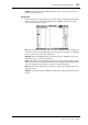
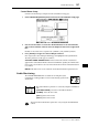
This is the Fader View page for the Input Channels.
PAN: This is the currently selected Input Channel’s Pan parameter. Select this parameter
using the cursor buttons, then press the [ENTER] button to set the Pan parameter to Cen-
ter. See “Panning Input Channels” on page 83 for more information.
ON/OFF: This is the On/Off parameter of the currently selected Input Channel. See “Mut-
ing Input Channels (ON/OFF)” on page 77 for more information.
Fader: This indicates the fader position of the currently selected Input Channel. The fader
knob appears highlighted when the fader is set to 0.0 dB. The fader position is displayed
numerically below the fader. See “Setting Input Channel Levels” on page 79 for more infor-
mation.
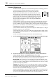
SURROUND PAN: The Surround pan parameters for the currently selected Input Chan-
nel are displayed only when a Surround mode other than Stereo is selected. See “Using Sur-
round Pan” on page 85 for more information.
BUS ROUTING: This section contains Routing and Follow Pan buttons for the currently
selected Input Channel. See “Routing Input Channels” on page 82 for more information.
The Direct Out output patch can also be set. See “Patching Direct Outs” on page 70 for more
information.
AUX: These are the currently selected Input Channel’s Aux Send Level, On/Off, and
Pre/Post parameters. While a rotary control is selected, the Aux Send can be turned on and
off by pressing [ENTER]. See “Aux Sends” on page 98 for more information.
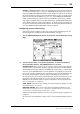
Meters: These meters indicate the levels of the currently selected Input Channel and its
horizontal or vertical partner. The metering position is displayed below them.
GROUP: These buttons indicate which Fader, Mute, EQ, or Comp group, if any, the cur-
rently selected Input Channel is in.