
Operation Manual


Automix Memory Page 175
02R96 Version 2—Owner’s Manual
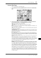
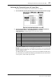
Automix Memory Page
Automixes can be stored and recalled on the Automix Memory page. The lower half of this
page is identical to the Automix Main page.
1 Use the DISPLAY ACCESS [AUTOMIX] button to locate the Automix Memory
page.
2 Use the cursor buttons to select the parameters, and use the Parameter
wheel, INC/DEC buttons, and [ENTER] button to set them.
The Automix library functions are explained in “Automix Library” on page 151. The
remaining items are the same as on the Main page and are explained on page 171.
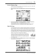
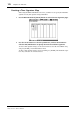
Fader Edit Pages
During playback, fader positions are displayed graphically as black bars on the Fader Edit
page, of which there are three. The Fader Edit 1 page displays Faders positions for Input
Channel 1 through 56, the Bus Outs, and Stereo Out. The Fader Edit 2 page displays faders
positions for Input Channel 1 through 56, the Bus Outs, and Aux Sends. The Fader Edit 3
page displays fader positions for the Input Group Master Levels and Output Group Master
Levels. When the Fader mode is set to Fader, Input and Output Channel levels are displayed.
When it’s set to Aux mode, Aux Send levels are displayed.
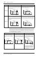
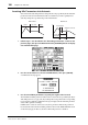
During rerecording, arrows are displayed next to each fader bar. A
downward arrow indicates that the current fader position is higher
than that specified by the existing fader data. An upward arrow indi-
cates that the current fader position is lower than that specified by
the existing fader data.
1 Use the DISPLAY ACCESS [AUTOMIX] button to locate the Fader Edit pages.
The Fader Edit 1 page is shown here.