
Operation Manual

336 Appendix D: Options
02R96 Version 2—Owner’s Manual
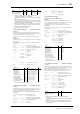
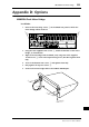
Meter Bridge Controls
A Channel indicators
These indicators show which channels are currently being
metered: Input Channels 1–24, 25–48, or 49–56 and Aux
Sends 1–8 and Bus Outs 1–8.
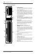
B INPUT METERING POSITION button & indicators
This button is used to set the metering position for Input
Channels to pre-EQ, pre-fader, or post-fader. It works in
unison with the PRE EQ, PRE FADER, and POST FADER
buttons for Input Channels on the Meter pages. The indica-
tors show the current setting.
C PEAK HOLD button
This button is used to turn the Peak Hold function on and
off. Its indicator lights up when Peak Hold is on. It works in
unison with the PEAK HOLD buttons on the Meter pages.
D LAYER buttons
These button are used to select Layers for metering. The
button indicator for the currently selected Layer lights up. If
the Meter Follow Layer preference is on (see page 231),
these Layers are selected automatically when the LAYER
buttons on the 02R96 are pressed.
E OUTPUT METERING POSITION button &
indicators
This button is used to set the metering position for Output
Channels to pre-EQ, pre-fader, or post-fader. It works in
unison with the PRE EQ, PRE FADER, and POST FADER
buttons for Output Channels on the Meter pages. The indi-
cators show the current setting.
F Meters
These 12-segment LED meters display the signals levels of
the channels on the currently selected Layer.
G STEREO meters
These 32-segment meters display the signal levels of the Ste-
reo Out.
H CONTROL ROOM button
This button is used to display the level of the Control Room
signal on the STEREO meters. Its indicator lights up when
the STEREO meters are displaying Control Room levels.
I BUS meters
These 12-segment LED meters display Bus Out signal levels.
56
OVER
1
3
4
7
6
8
2
5
9