
User`s manual


4-16
CHAPTER 4 Specifications
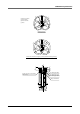
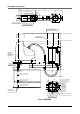
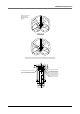
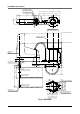
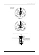
Fig. 4-6 YK800XS
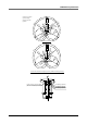
Z-axis 200mm stroke
Z-axis 400mm stroke
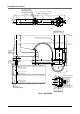
Use M12 bolt for installation
(Installation base of larger than
φ232mm may interfere with harness.)
Z-axis stroke 200mm
Working envelope
Z-axis stroke 300mm
Working envelope
70
R20
R150
180
106 93
7575
80
70
147
4-φ14
301
101
120
419±2
375
562
328
279
97
20
0
112
R106
200
400
45
50.5
φ8
M12X1.75 Depth20
106
450
350
126
58
User tubing 3 (φ6 blue)
User tubing 2 (φ6 red)
User tubing 1 (φ6 black)
D-sub connector for user wiring
(No. 1 to 20 usable)
R76
φ22
0
-0.021
5
5
φ232
Recommended user installation base
8
12
12
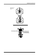
Z-axis upper end
mechanical stopper
position
Center of recommended
user installation base
A
View from direction A
Z-axis lower end
mechanical stopper
position
54 20
2X2-M4X0.7
Depth10
(Same on
opposite side)
41