
Service manual


YCC-S (Yamaha Chip Controlled-Shift) SYSTEM
– 108 –
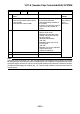
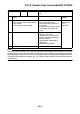
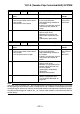
Fault code No. Sh_ _21 Symptom Output signal of gear position sensor is abnor-
mal.
Order Item/components and probable
cause
Check or maintenance job Reinstatement
method
1 Connections
• Wire harness MCU (motor control
unit) coupler
• Gear position sensor coupler
• Check the coupler for any pins
that may be pulled out.
• Check the locking condition of
the coupler.
• If there is a malfunction, repair it
and connect the coupler se-
curely.
Repairing the
cause of the
malfunction.
2 Open or short circuit in wire harness. • Repair or replace if there is an
open or short circuit.
• Between gear position sensor
coupler and MCU (motor con-
trol unit) coupler.
(yellow–yellow)
(blue–blue)
(black/blue–black/blue)
3 Defective gear position sensor. • Adjust or replace if defective.
Refer to “ADJUSTING THE
GEAR POSITION SENSOR” on
page 50 and “CHECKING THE
GEAR POSITION SENSOR” on
page 132.
4 Gear position setting • Execute the diagnostic mode.
(Code No. Sh_ _65)
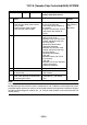
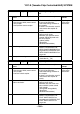
Fault code No. Sh_ _22 Symptom Output signal of foot shift switch is abnormal.
Order Item/components and probable
cause
Check or maintenance job Reinstatement
method
1 Connections
• Wire harness MCU (motor control
unit) coupler
• Foot shift switch coupler
• Check the coupler for any pins
that may be pulled out.
• Check the locking condition of
the coupler.
• If there is a malfunction, repair it
and connect the coupler se-
curely.
Repairing the
cause of the
malfunction.
2 Open or short circuit in wire harness
and/or sub-lead 2.
• Repair or replace if there is an
open or short circuit.
• Between foot shift switch cou-
pler and MCU (motor control
unit) coupler.
(orange/red–orange/black)
(blue–blue)
(black/blue–black/blue)
3 Defective foot shift switch. • Adjust or replace if defective.
Refer to “ADJUSTING THE
FOOT SHIFT SWITCH” on
page 60 and “CHECKING THE
FOOT SHIFT SWITCH” on
page 133.