WaveRunner VX 700 VX 700 (F2V) SERVICE MANUAL F2V-28197-ZN-11
Preface This manual has been prepared by Yamaha primarily for use by Yamaha dealers and their trained mechanics when performing maintenance procedures and repairs to Yamaha equipment. It has been written to suit the needs of persons who have a basic understanding of the mechanical and electrical concepts and procedures inherent in the work, for without such knowledge attempted repairs or service to the equipment could render it unsafe or unfit for use.
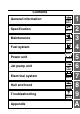
Contents General information Specification Maintenance Fuel system Power unit Jet pump unit GEN INFO SPEC MNT FUEL POWR JET PUMP – Electrical system Hull and hood Troubleshooting Appendix + ELEC HULL HOOD TRBL SHTG 1 2 3 4 5 6 7 8 9 A
GEN INFO General information Safety while working ..................................................... 1-1 Rotating part............................................................................... 1-1 Hot part....................................................................................... 1-1 Electric shock ............................................................................. 1-1 Impeller.......................................................................................
GEN INFO General information Safety while working To prevent an accident or injury and to provide quality service, observe the following safety procedures. Rotating part • Hands, feet, hair, jewelry, clothing, personal flotation device straps, and so on, can become entangled with internal rotating parts of the engine or jet pump unit, resulting in serious injury or death.
Safety while working Ventilation Working with crane • Gasoline vapor and exhaust gas are heavier than air and extremely poisonous. If gasoline vapor or exhaust gas is inhaled in large quantities, it may cause loss of consciousness and death within a short time. • When test running an engine indoors (for example, in a water tank) make sure to do so where adequate ventilation can be maintained.
GEN INFO General information Handling of heat gun Special service tool • Improper handling of a heat gun may result in burns. For information on the proper handling of the heat gun, see the operation manual issued by the manufacturer. • When using a heat gun, keep it away from the gasoline and oil, to prevent a fire. • Components become hot enough to cause burns. Do not touch any hot components directly. Use the recommended special service tools to work safely, and to protect parts from damage.
Safety while working Disassembly and assembly • Use compressed air to remove dust and dirt during disassembly. • Apply engine oil to the contact surfaces of moving parts before assembly. 1 • Install bearings so that the bearing identification mark is facing in the direction indicated in the installation procedure. In addition, make sure to lubricate the bearings liberally. • Apply a thin coat of water resistant grease to the lip and periphery of an oil seal before installation.
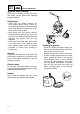
GEN INFO General information How to use this manual Manual format The format of this manual has been designed to make service procedures clear and easy to understand. Use the information below as a guide for effective and quality service. • Parts are shown and detailed in an exploded diagram and are listed in the component list (see 1 in the following figure for an example page).
How to use this manual Abbreviation The following abbreviations are used in this service manual.
GEN INFO General information Adhesive, lubricant, sealant, and thread locking agent Symbol Symbols in an exploded diagram or illustration indicate the grade of lubricant and the lubrication points.
Adhesive, lubricant, sealant, and thread locking agent / Special service tool Special service tool Special service tools with Yamaha part numbers (90890-*****) are distributed by the Parts Division.
GEN INFO General information Stopper guide stand 90890-06538 Drive shaft holder 5 90890-06519 Driver rod LS 90890-06606 Digital circuit tester 90890-03174 Ball bearing attachment 90890-06631 Peak voltage adapter B 90890-03172 Crankshaft holder 20 90890-06552 Ignition tester (Spark gap tester) 90890-06754 Bearing outer race attachment 90890-06628 1-9
Special service tool / Model feature Model feature Identification number Primary I.D. number The primary I.D. number is stamped on a label attached to the inside of the engine compartment. 1 2 Jet pump unit serial number The jet pump unit serial number is stamped on a label attached to the intermediate housing. 3 PRI-I.D. MODEL Starting engine serial number: 6CP: 1000001 2 F2V 1 3 YAMAHA MOTOR CO., LTD. ASSEMBLED IN U.S.A. FROM AMERICAN AND JAPANESE COMPONENTS.
GEN INFO General information — MEMO — 1-11
SPEC Specification Model data .......................................................................... 2-1 Model code................................................................................. 2-1 Dimension and weight ................................................................ 2-1 Performance............................................................................... 2-1 Power unit .................................................................................. 2-1 Drive unit ............
SPEC Specification Model data Model code Item Unit Hull Engine/jet Model VX 700 F2V 6CP/6CP Dimension and weight Item Length Width Height Dry weight Maximum capacity Unit mm (in) mm (in) mm (in) kg (lb) Person/ kg (lb) Model VX 700 3220 (126.8) 1170 (46.1) 1160 (45.7) 283 (624) 3/240 (530) Performance Item Full throttle operating range Trolling speed Maximum fuel consumption Cruising range Unit r/min r/min L/h (US gal/ h, lmp.gal/h) h Model VX 700 7200 1250–1350 34.0 (9.0, 7.5) 1.
Model data Drive unit Item Jet pump type Impeller rotation Transmission Jet thrust nozzle horizontal angle Trim system Jet thrust nozzle trim angle Unit Model VX 700 Axial flow, single stage Counterclockwise (viewed from rear) Constant mesh 1-speed Degree 24 + 24 Degree — 3 Fuel and oil requirement Item Fuel type Fuel minimum rating Unit PON RON Model VX 700 Regular unleaded gasoline 86 90 Fuel tank capacity L (US gal, Imp.gal) L (US gal, Imp.
SPEC Specification Fuel system technical data Fuel system Item Carburetor Manufacturer Model × quantity Type ID mark Main jet (MJ) Main nozzle (MN) Pilot jet (PJ) Low speed screw Throttle valve Valve seat size Arm height High speed screw Throttle lever free play Unit mm (in) turns out mm (in) mm (in) turns out mm (in) Model VX 700 Mikuni BN38 × 2 Floatless 62T03F/03R 120 (front), 130 (rear) 2.5 (0.10) 67.5 5/8 ± 1/4 190 1.5 (0.06) 0–0.2 (0–0.008) 5/8 ± 1/4 (front), 1 1/8 ± 1/4 (rear) 4.0–7.0 (0.16–0.
Fuel system technical data / Power unit technical data Crank case assy.
SPEC Specification Jet pump unit technical data Jet pump unit Item Impeller housing Inside diameter Impeller-to-housing clearance Clearance limit Impeller Material Blades number Pitch angle Drive shaft Runout limit Intermediate drive shaft Runout limit Nozzle Diameter maximum difference of jet thrust nozzle distances Unit Model VX 700 mm (in) 155.35–155.45 (6.116–6.120) mm (in) 0.35–0.45 (0.014–0.018) mm (in) 0.60 (0.024) Degree Stainless steel 3 13.2 mm (in) 0.01 (0.0004) mm (in) 0.30 (0.
Jet pump unit technical data / Electrical technical data Charging system Unit Model VX 700 V V V V 180 20 210 150 Ω 497.7–608.3 V V V 8.7 25.6 47.3 Ω 1.143–1.397 A at r/min 14 at 6000 V 13.0 Unit Model VX 700 Ω 0.078–0.106 kΩ 14.336–30.464 V °C (°F) °C (°F) 11.0–12.
SPEC Specification Starting system Unit Model VX 700 V/A 12/10 kW Seconds mm (in) mm (in) mm (in) Constant mesh 0.8 30 27.0–28.0 (1.06–1.10) 0.2–0.7 (0.008–0.028) 6.5–12.5 (0.26–0.49) Item Fuse Rating Main Starter motor Type Output Cranking time limit Commutator diameter Commutator undercut (*1) Brush length (*1) The figures are for reference only.
Electrical technical data / Specified tightening torque Specified tightening torque Fuel system Screw size ø4 — ø3 — — — — — Part to tightened Fuel cock knob screw Fuel cock assy./washer nut Choke knob screw Choke knob nut Oil filler neck/rubber seal nut Oil filler hose clamp Fuel filler neck/rubber seal nut Fuel filler hose clamp Fuel level sensor assy. clamp Carburetor cover 1 bolt Flame arrester holder bolt Throttle cable locknut Choke cable locknut Carburetor assy. nut Needle valve assy.
SPEC Specification Screw size M5 M6 M6 — Part to tightened Reed valve assy. bolt Intake manifold bolt Thermoswitch bolt Spark plug Cylinder head bolt Cylinder bolt Anode screw Starter motor bolt Starter motor positive lead nut Flywheel cover bolt Flywheel magneto bolt Drive coupling Base assy.
Specified tightening torque Jet pump unit Part to tightened Intake grate bolt Ride plate bolt Cover screw Steering cable joint nut Jet pump unit assy. bolt Rubber plate bolt Rubber plate nut Screw size M6 M10 M8 ø5 — M6 M10 M6 — See page 6-1 6-1 6-1 6-1 6-2 6-2 6-2 6-2 6-2 6-2 6-2 6-2 6-2 6-5 6-5 M8 M10 M6 7 0.7 5.2 6-5 M6 M22 — — M8 — M6 M24 M24 8 75 26 5.5 17 4 7 36 36 0.8 7.5 2.6 0.55 1.7 0.4 0.7 3.6 3.6 5.9 55.3 19.2 4.1 12.5 3.0 5.2 26.6 26.
SPEC Specification Hull and hood Part to tightened Upper handlebar cover screw Lower handlebar cover screw Grip end bolt Left handlebar switch assy. screw Throttle lever assy. bolt Handlebar holder bolt Mirror nut Hood lock bolt Front hood screw Hinge nut Hinge bolt Engine hatch cover nut Engine hatch cover bolt Multifunction meter screw Steering cable stopper bolt Steering master assy. bolt Steering arm assy. bolt Ball joint nut Ball joint Buzzer bracket bolt Case assy.
Specified tightening torque / General tightening torque General tightening torque This chart indicates the tightening torques for standard fasteners with a standard ISO thread pitch. Tightening torque specifications for special components and assemblies are provided in the applicable sections of this manual. To prevent warpage, tighten multifastener assemblies in a crisscross fashion and progressive stages until the specified torque is reached.
SPEC Specification Cooling system To exhaust outlet To stern outlet 5 7 6 To pilot outlet 3 2 4 From flushing hose From jet pump 1 cooling water flow 7 Water lock 6 Exhaust outer cover 1 5 Exhaust chamber 4 Exhaust ring 3 Cylinder head 2 Cylinder block Pilot outlet Flushing hose Jet pump Water 2-13 Stern outlet 1 Exhaust manifold Exhaust outlet
Cooling system / Cable and hose routing Cable and hose routing Starboard bow view 4 5 6 7 8 3 9 2 1 0 J A I H G F E D C 1 Positive battery cable 2 Battery breather hose 3 Flushing hose 4 Bilge hose 5 Cooling water pilot outlet hose 6 Choke cable 7 Oil tank breather hose 8 Buzzer lead 9 Multifunction meter lead 0 Left handlebar switch lead A Fuel level sensor lead B B Fuel tank breather hose C Oil level sensor lead D Throttle cable E Oil hose F Steering cable G Wiring harness H Spark plug lea
SPEC Specification Top view 8 9 A N 6 K C B M 0 7 L D 5 E G I H O 1 2 4 3 J F 1 Positive battery cable 2 Battery breather hose 3 Flushing hose 4 Bilge hose 5 Cooling water pilot outlet hose 6 Choke cable 7 Oil tank breather hose 8 Buzzer lead 9 Multifunction meter lead 0 Left handlebar switch lead A Fuel level sensor lead 2-15 B Fuel tank breather hose C Oil level sensor lead D Throttle cable E Oil hose F Steering cable G Wiring harness H Spark plug lead (#1) I Spark plug lead (#2) J Cool
Cable and hose routing 8 9 A N 6 K C B M 0 7 L D 5 E G I H O 1 2 4 3 J F M Fuel hose N Fuel reservoir hose O Negative battery cable 2-16 1 2 3 4 5 6 7 8 9 A
SPEC Specification Port view 9 0 8 7 6 5 G L H I 1 2 4 3 C A D N M B F 1 Positive battery cable 2 Battery breather hose 3 Flushing hose 4 Bilge hose 5 Cooling water pilot outlet hose 6 Choke cable 7 Oil tank breather hose 8 Buzzer lead 9 Multifunction meter lead 0 Left handlebar switch lead A Fuel level sensor lead 2-17 E K O B Fuel tank breather hose C Oil level sensor lead D Throttle cable E Oil hose F Steering cable G Wiring harness H Spark plug lead(#1) I Spark plug lead(#2) J Coo
Cable and hose routing 9 0 8 7 6 5 G L H I 1 2 4 3 C A D N M B F E K O J M Fuel hose N Fuel reservoir hose O Negative battery cable 2-18 1 2 3 4 5 6 7 8 9 A
SPEC Specification — MEMO — 2-19
MNT Maintenance Maintenance interval chart ................................................ 3-1 Periodic service.................................................................. 3-2 Steering system.......................................................................... 3-2 Steering master check ...................................................................3-2 Throttle lever free play check .........................................................3-2 Throttle lever free play adjustment..............
MNT Maintenance Maintenance interval chart The following chart should be considered strictly as a guide to general maintenance intervals. Depending on operating conditions, the maintenance intervals should be changed.
Maintenance interval chart / Periodic service Periodic service Steering system Steering master check 1. Turn the handlebar lock to lock and push it back and forth. Throttle lever free play adjustment Follow all the steps if the throttle cable has been replaced. After adjusting the throttle lever free play, make sure that the throttle cable is not pulled when the handlebar is turned to the right and left. 1. Face the handlebar straight ahead. 2.
MNT Maintenance 7. Remove the upper handlebar cover. See “Steering pad and handlebar cover” (81). Fuel filter check 1. Check the fuel filter 1. Replace the fuel filter if cracked or damaged. 8. Slide the rubber cover 4 away from the throttle lever, and then loosen the locknut 5. 2. Replace the fuel filter if there are water contaminants, and check for water in the fuel tank. See “Fuel tank check” (3-3). 9. Turn the adjuster 6 in or out until the specified free play b is obtained.
Periodic service Water separator check 1. Check the water separator 1. Drain the water if water has accumulated. 2. Check the O-ring of the drain plug. Replace the O-ring if cracked or damaged. See “Water separator check” (821). 1 Oil hose, oil filler cap and rubber seal check 1. Check the oil hose, or oil filler cap. Replace if cracked or damaged. 2. Check the rubber seal. Replace if cracked or worn. TIP: To drain water from the water separator, loosen the drain plug. Choke cable check 1.
MNT Maintenance 4. Measure the spark plug gap b. Replace if out of specification. 3. Stop the engine. 4. Remove the spark plug caps, and then remove the plugs. 5. Install the special service tool 1. b Specified spark plug (manufacturer): BR8HS (NGK) Spark plug gap b: 0.6–0.7 mm (0.024–0.028 in) 5. Tighten the spark plugs to the specified torque. Spark plug: 25 N·m (2.5 kgf·m, 18.4 ft·lb) TIP: Before installing a spark plug, clean the gasket surface and spark plug surface. 6.
Periodic service Engine oil level check Digital tachometer 1: 90890-06760 Do not allow the oil tank to become completely empty. If the oil tank becomes empty the oil injection pump must be bled to ensure proper oil flow, otherwise engine damage may occur. See “Oil pump air bleeding” (4-18). Trolling speed: 1250–1350 r/min Trolling speed adjustment 1. Turn the low speed screws 1 until they are lightly seated, and then turn out the low speed screws 1 to the specified number of turns.
MNT Maintenance Nut and bolt check 1. Check the engine, deck, and hull for loose bolts and nuts. Tighten if loose. See “Specified tightening torque” (2-8). a Jet pump unit Impeller check 1 Make sure to remove the battery before checking the jet pump unit. 1. Remove the jet pump unit. See “Jet pump unit removal” (6-4). 2. Check the impeller 1. Replace if damaged. 3. Measure the impeller-to-housing clearance a.
Periodic service 3. Disconnect the steering cable joint 2 from the ball joint 3. 4. Turn the steering cable joint 2 in or out to adjust distances a and b. WARNING! The steering cable joint must be screwed in more than 8 mm (0.31 in) c. 3 2 1 b b 7. If the jet thrust nozzle steering angle cannot be properly adjusted using the cable joint at the steering master end, adjust the cable joint at the jet pump end so that the difference of distances a and b is within specification.
MNT Maintenance Be careful not to place the battery on its side. Make sure to remove the battery from the battery compartment when adding battery electrolyte or charging the battery. When checking the battery, make sure the breather hose is connected to the battery and not obstructed. 1. Disconnect the negative battery cable 1, positive battery cable 2, and battery breather hose 3. NOTICE: When removing the battery, disconnect the negative battery cable first. 5.
Periodic service TIP: Before lubricating the throttle cable, squeeze the throttle lever, and then remove the rubber seal 1. 2. Lubricate the throttle cable (carburetor end). TIP: 3. Lubricate the choke cable (carburetor end). Remove the bilge strainer case 1 by pushing the hooks on the bilge strainer inward. 3. Install the bilge strainer case 1. Drain plug check 1. Check the O-ring of each drain plug. Replace if cracked or damaged. See “Drain plug check” (8-29).
MNT Maintenance Recommended lubricant: Yamaha grease A TIP: Disconnect the joint and apply a small amount of grease.
FUEL Fuel system Fuel cock and fuel filter ..................................................... 4-1 Fuel filter check .......................................................................... 4-2 Fuel cock check.......................................................................... 4-2 Choke cable ........................................................................ 4-3 Oil tank ................................................................................ 4-4 Oil line check ....................
FUEL Fuel system Fuel cock and fuel filter (RES) 2 N • m (0.2 kgf • m, 1.5 ft • Ib) 6 (OUT) (ON) 5 4 3 2 1 9 8 7 5 N • m (0.5 kgf • m, 3.7 ft • Ib) No. 1 2 3 4 5 6 7 8 9 4-1 Part name Screw Fuel cock knob Nut Washer Fuel cock assy.
Fuel cock and fuel filter Fuel filter check See “Fuel system” (3-3). Fuel cock check Before checking the fuel system, remove the battery, and then remove the fuel filler cap to reduce any pressure inside the fuel tank. 1. Check the fuel cock. Replace if there is rough movement.
FUEL Fuel system Choke cable 2 N • m (0.2 kgf • m, 1.5 ft • Ib) 5 1 4 3 2 N • m (0.2 kgf • m, 1.5 ft • Ib) 2 No.
Choke cable / Oil tank Oil tank 11 6 3 7 (VENT) 12 10 4 8 2 1 5 9 3.7 N • m (0.37 kgf • m, 2.7 ft • Ib) 14 6 N • m (0.6 kgf • m, 4.4 ft • Ib) 15 13 No.
FUEL Fuel system Oil line check 1. Clean the oil filter, and then check the oil filter. Replace if frayed or teared. 2. Check the rubber seal. Replace if cracked or worn. 3. Check the hoses. Replace if cracked or damaged. 4. Check the oil tank filler cap. Replace if cracked or damaged. Oil level sensor check See “Indication system” (7-15). Oil tank check 1. Check the oil tank. Replace if cracked or damaged.
Oil tank / Fuel tank Fuel tank (RETURN) 10 (RES) 6 (VENT) 3 9 (ON) 4 7 2 (VENT) 14 8 1 6 N • m (0.6 kgf • m, 4.4 ft • Ib) 13 11 12 5 3.7 N • m (0.37 kgf • m, 2.7 ft • Ib) 1 3.7 N • m (0.37 kgf • m, 2.7 ft • Ib) 1 N • m (0.1 kgf • m, 0.7 ft • Ib) No.
FUEL Fuel system Check valve check 1. Blow into the end a of the check valve, and make sure that airflow from the end b is unrestricted. Replace if the air flow is restricted. 2. Blow into the end b of the check valve, and make sure that airflow from the end a is restricted. Replace if the air flow is unrestricted. È a É b b a È Upright É Inverted Fuel level sensor check See “Indication system” (7-15). Fuel tank check 1. Check the fuel tank. Replace if cracked or damaged. Fuel filler cap check 1.
Fuel tank / Carburetor unit Carburetor unit 1 N·m (0.1 kgf·m, 0.7 ft·Ib) 1 18 N·m (1.8 kgf·m, 13.3 ft·Ib) 14 17 19 2 18 17 8 N·m (0.8 kgf·m, 5.9 ft·Ib) 3 3 22 4 10 5 17 20 21 6 16 11 4 23 15 8 5 9 12 7 13 8 N·m (0.8 kgf·m, 5.9 ft·Ib) No.
FUEL Fuel system 1 N·m (0.1 kgf·m, 0.7 ft·Ib) 1 18 N·m (1.8 kgf·m, 13.3 ft·Ib) 14 17 19 2 18 17 8 N·m (0.8 kgf·m, 5.9 ft·Ib) 3 3 22 4 10 5 17 20 21 6 16 11 4 15 8 5 9 12 7 13 8 N·m (0.8 kgf·m, 5.9 ft·Ib) No. 16 17 18 19 20 21 22 23 4-9 Part name Throttle cable Band Fuel hose Pulse hose Fuel reservoir hose Nut Carburetor assy. Gasket Q’ty 1 3 1 1 1 4 1 1 Remarks a: 13–15 mm (0.51–0.
Carburetor unit Choke cable and throttle cable installation 1. Install the choke cable 1 and throttle cable 2, and then tighten the nuts to the specified torque. b c a 1 2 Choke cable and throttle cable guide installation position a: 14.0 ± 1.0 mm (0.55 ± 0.04 in) Choke cable nut b: 8 N·m (0.8 kgf·m, 5.9 ft·lb) Throttle cable nut c: 8 N·m (0.8 kgf·m, 5.9 ft·lb) 2. Adjust the throttle lever free play. See “Steering system” (3-2). Carburetor assy. check 1. Adjust the trolling speed.
FUEL Fuel system Carburetor and fuel pump 3.4 N • m (0.34 kgf • m, 2.5 ft • Ib) 1 N • m (0.1 kgf • m, 0.7 ft • Ib) 1 N • m (0.1 kgf • m, 0.7 ft • Ib) 1.8 N • m (0.18 kgf • m, 1.3 ft • Ib) 32 34 31 28 29 35 4.4 N • m (0.44 kgf • m, 3.2 ft • Ib) 36 33 30 19 37 38 39 22 21 20 11 40 41 2.0 N • m (0.2 kgf • m, 1.5 ft • Ib) 3 2 0.7 N • m (0.07 kgf • m, 0.5 ft • Ib) 23 27 26 25 24 10 9 6 8 15 16 18 14 17 43 No. 1 2 3 4 5 6 7 8 9 10 11 12 13 14 15 4-11 Part name Carburetor assy.
Carburetor and fuel pump 3.4 N • m (0.34 kgf • m, 2.5 ft • Ib) 1 N • m (0.1 kgf • m, 0.7 ft • Ib) 1 N • m (0.1 kgf • m, 0.7 ft • Ib) 1.8 N • m (0.18 kgf • m, 1.3 ft • Ib) 32 34 31 28 29 35 4.4 N • m (0.44 kgf • m, 3.2 ft • Ib) 36 33 30 19 37 38 39 22 21 20 11 40 41 2.0 N • m (0.2 kgf • m, 1.5 ft • Ib) 3 2 1 0.7 N • m (0.07 kgf • m, 0.5 ft • Ib) 23 27 26 25 24 10 9 6 8 15 16 18 14 17 43 No.
FUEL Fuel system 3.4 N • m (0.34 kgf • m, 2.5 ft • Ib) 1 N • m (0.1 kgf • m, 0.7 ft • Ib) 1 N • m (0.1 kgf • m, 0.7 ft • Ib) 1.8 N • m (0.18 kgf • m, 1.3 ft • Ib) 32 34 31 28 29 35 4.4 N • m (0.44 kgf • m, 3.2 ft • Ib) 36 33 30 19 37 38 39 22 21 20 11 40 41 2.0 N • m (0.2 kgf • m, 1.5 ft • Ib) 3 2 0.7 N • m (0.07 kgf • m, 0.5 ft • Ib) 23 27 26 25 24 10 9 6 8 15 16 18 14 17 42 12 13 43 No. 32 33 34 35 36 37 38 39 40 Arm Pin Screw Plate Needle valve assy. Screw Body assy.
Carburetor and fuel pump Diaphragm check 1. Check the diaphragm. Replace if damaged. Arm check 1. Check the arm 1. Repair if bent. Replace if damaged. 2. Measure the arm height a. TIP: Always replace the body assy. and valve (clear film) as a set. Needle valve check 1. Clean the needle valve assy., and then check the needle valve assy. Replace if worn a. 1 b Arm height a: 0–0.2 mm (0–0.008 in) TIP: • Measure the distance between the surface of the carburetor body b and the top surface of the arm.
FUEL Fuel system TIP: Before disassembling the carburetor, make sure to note the number of times the speed screw is turned in from its set position to the seated position. Fuel pump check 1. Check the fuel pump gasket, diaphragm, fuel pump diaphragm, fuel pump diaphragm body, and valve seat. Replace if damaged. Fuel filter check 1. Clean the fuel filter, and then check the fuel filter. Replace if damaged. High and low speed screw adjustment 1.
Carburetor and fuel pump Carburetor assy. check 1. Adjust the trolling speed. See “Power unit” (3-4).
FUEL Fuel system Oil pump 5 N·m (0.5 kgf·m, 3.7 ft·Ib) 9 9 11 3 10 9 9 4 3 8 5 12 10 LT 572 6 7 1 LT 8 N·m (0.8 kgf·m, 5.9 ft·Ib) 572 2 6 No. 1 2 3 4 5 6 7 8 9 10 11 12 4-17 Part name Band Oil hose Hose clamp Oil delivery hose 1 Oil delivery hose 1 Bolt Oil pump Gasket Hose clamp Check valve Oil delivery hose 2 Oil delivery hose 2 Q’ty 1 1 2 1 1 2 1 1 4 2 1 1 Remarks 85 mm (3.35 in) 70 mm (2.76 in) M6 × 35 mm Not reusable 210 mm (8.27 in) 450 mm (17.
Oil pump Oil pump check 1. Place rags around the air bleed screw 1 to catch any oil that might spill. • If the oil delivery hoses are not full of oil, fill them up. • After installing the oil injection system, bleed the system of any air. 2. Fill the oil tank with the recommended oil. 1. Clean the oil pump, and then check the oil pump. Replace if damaged or worn. 1 Oil hose check • If the oil delivery hoses are not full of oil, fill them up.
POWR Power unit Engine unit.......................................................................... 5-1 Engine mount ..................................................................... 5-3 Engine unit removal.................................................................... 5-4 Engine mount check................................................................... 5-6 Engine unit installation ............................................................... 5-6 Exhaust ring .............................
Crankcase ......................................................................... 5-30 Crankcase check...................................................................... 5-32 Crankcase installation .............................................................. 5-32 Crankshaft ........................................................................ 5-33 Crankshaft check......................................................................
POWR Power unit Engine unit 15 N·m (1.5 kgf·m, 11.1 ft·Ib) 5 4 3 15 7 8 N·m (0.8 kgf·m, 5.9 ft·Ib) 8 N·m (0.8 kgf·m, 5.9 ft·Ib) 14 11 14 18 LT 572 8 12 11 9 5 N·m (0.5 kgf·m, 3.7 ft·Ib) 13 17 N·m (1.7 kgf·m, 12.5 ft·Ib) 16 2 10 LT 17 1 271 6 No.
Engine unit 15 N·m (1.5 kgf·m, 11.1 ft·Ib) 5 4 3 15 7 8 N·m (0.8 kgf·m, 5.9 ft·Ib) 8 N·m (0.8 kgf·m, 5.9 ft·Ib) 14 11 14 18 LT 572 8 12 11 9 5 N·m (0.5 kgf·m, 3.7 ft·Ib) 13 17 N·m (1.7 kgf·m, 12.5 ft·Ib) 16 2 10 LT 17 1 271 6 No. 14 15 16 17 18 Part name Bolt/collar Coupling cover Bolt/washer Shim Engine unit Q’ty 2/2 1 4/4 * 1 Remarks M6 × 25 mm M8 × 35 mm *: As required.
POWR Power unit Engine mount 17 N·m (1.7 kgf·m, 12.5 ft·Ib) BOW 2 1 3 2 1 3 5 4 1 17 N·m (1.7 kgf·m, 12.5 ft·Ib) 1 1 6 6 2 No.
Engine mount 6. Remove the band 6, and then disconnect the cooling water hose 7. Engine unit removal Before removing the engine, make sure to take adequate measures to protect the deck opening from damage. 7 6 1. Disconnect the negative battery cable, and then disconnect the positive battery cable. 2. Remove the service lid. 3. Disconnect the multifunction meter couplers 1, and then remove the plastic ties 2. 7. Remove the band 8, and then disconnect the cooling water hose 9. 8 9 2 2 1 4.
POWR Power unit K C D J 11. Remove the band E, and then disconnect the fuel hose F. E 15. Remove the coupling cover L. L F 16. Loosen the engine mounting bolts M. TIP: When removing the fuel hose, remove the fuel filler cap to reduce any pressure inside the fuel tank. 12. Remove the band G, and then disconnect the fuel hose H. 13. Remove the fuel hose H from the plastic ties I. 17. Lift the engine unit slightly, remove the shims N, and then lower the unit.
Engine mount 19. Suspend the engine unit using an engine hangers, and then separate the unit from the engine mounts and move it forward to disconnect the coupling. NOTICE: When removing the engine unit, take care to avoid causing damage to the hull liner and deck opening. 1 TIP: Do not install the rubber damper until the coupling clearance adjustment has been made. 2. Temporarily install the engine mounting bolts 2 and washer 3. 3.
POWR Power unit Clearance a: Less than 1.0 mm (0.039 in) (without rubber damper) Clearance b: 2.0–4.0 mm (0.079–0.157 in) 11. Check that the coupling clearances a and b are within specification. Readjust if out of specification. a Available shim thicknesses: 0.10, 0.30, 0.50, 1.00, and 2.00 mm 5. Lift the engine unit slightly, remove the shims 4, and then lower the engine unit. 6. Remove the engine mounting bolts 2 and washer 3. 7.
Engine mount c d e 0 G F 9 19. Connect the cooling water hose H to hose joint I. Choke cable and throttle cable guide installation position c: 14.0 ± 1.0 mm (0.55 ± 0.04 in) 20. Connect the exhaust hose J. I Choke cable nut d: 8 N·m (0.8 kgf·m, 5.9 ft·lb) Throttle cable nut e: 8 N·m (0.8 kgf·m, 5.9 ft·lb) 15. Connect the fuel hose A, and then install the band B. H J 16. Install the plastic ties C. C 21. Connect the cooling water hose K, and then install the band L. L A K B 17.
POWR Power unit 23. Install the fuse box assy. O, and then tighten the nuts P to the specified torque. 24. Install the band Q. O P Q Electrical box nut P: 15 N·m (1.5 kgf·m, 11.1 ft·lb) 25. Install the plastic ties R. R 26. Connect the multifunction meter couplers S, and then install the plastic ties T. T T S 27. Install the service lid. 28. Connect the positive battery cable, and then connect the negative battery cable. 29.
Engine mount / Exhaust ring Exhaust ring 2 N·m (0.2 kgf·m, 1.5 ft·Ib) 2 11 2 N·m (0.2 kgf·m, 1.5 ft·Ib) 2 2 N·m (0.2 kgf·m, 1.5 ft·Ib) 1 1 3 9 10 6 1 5 7 8 4 29 N·m (2.9 kgf·m, 21.4 ft·Ib) No.
POWR Power unit Exhaust chamber assy. 2 2 N·m (0.2 kgf·m, 1.5 ft·Ib) 5 46 N·m (4.6 kgf·m, 33.9 ft·Ib) 3 2 N·m (0.2 kgf·m, 1.5 ft·Ib) 6 39 N·m (3.9 kgf·m, 28.8 ft·Ib) 6 2 5 7 3 2 2 4 2 1 2 N·m (0.2 kgf·m, 1.5 ft·Ib) 4 39 N·m (3.9 kgf·m, 28.8 ft·Ib) 8 9 1 10 No. 1 2 3 4 5 6 7 8 9 10 5-11 Part name Exhaust ring Clamp/exhaust hose Band Joint Hose Hose Bolt Bolt Muffler stay Bolt Exhaust chamber assy. Q’ty 1/1 4 1 1 1 2 4 1 2 1 Remarks See “Exhaust ring” (5-10).
Exhaust chamber assy. / Exhaust chamber Exhaust chamber 8 N·m (0.8 kgf·m, 5.9 ft·Ib) 8 N·m (0.8 kgf·m, 5.9 ft·Ib) No.
POWR Power unit Muffler 1 21 N·m (2.1 kgf·m, 15.5 ft·Ib) 2 39 N·m (3.9 kgf·m, 28.8 ft·Ib) È LT 271 2 4 1 LT 3 No. 1 2 3 4 5-13 Part name Exhaust chamber Clamp/cooling water hose Bolt Muffler Gasket 271 Q’ty 1/1 8 1 1 Remarks See “Exhaust chamber assy.” (5-11).
Muffler / Reed valves Reed valves 8 N·m (0.8 kgf·m, 5.9 ft·Ib) 8 N·m (0.8 kgf·m, 5.9 ft·Ib) 1 N·m (0.1 kgf·m, 0.7 ft·Ib) 4 N·m (0.4 kgf·m, 3.0 ft·Ib) No. 1 2 3 4 5 6 7 8 9 10 11 12 Part name Carburetor assy. Bolt Plate Bolt Bolt Intake manifold Screw Reed valve assy. Plate Gasket Screw Valve stopper Reed valve Q’ty 2 1 8 3 1 4 2 1 2 16 8 8 Remarks See “Carburetor unit” (4-8).
POWR Power unit Reed valve check 1. Check the reed valves. Replace if cracked or damaged. 2. Measure the valve warpage a. Replace if out of specification. Valve warpage limit: 0.2 mm (0.01 in) 3. Measure the valve stopper height b. Replace if out of specification. Valve stopper height: 8.8–9.2 mm (0.35–0.
Reed valves / Cylinder head Cylinder head 1 15 N·m (1.5 kgf·m, 11.1 ft·Ib) 2 29 N·m (2.9 kgf·m, 21.4 ft·Ib) 3 25 N·m (2.5 kgf·m, 18.4 ft·Ib) 4 8 N·m (0.8 kgf·m, 5.9 ft·Ib) 5 6 No. 1 2 3 4 5 6 Part name Exhaust chamber assy. Bolt Thermoswitch Spark plug Bolt Cylinder head Gasket Q’ty 2 1 2 10 1 1 Remarks See “Exhaust chamber assy.” (5-11).
POWR Power unit Cylinder head check Do not use a sharp instrument to avoid damaging or scratching the cylinder head or spark plug bore threads. 1. Eliminate the carbon deposits (using a rounded scraper 1). TIP: Place 400–600 grit wet sandpaper on a surface plate and resurface the cylinder head using a figure-eight sanding pattern. Cylinder head installation 1. Install the cylinder head, and then tighten the bolts to the specified torque in the order 1, 2, and so on. 4 5 1 8 9 7 0 2 2.
Cylinder head / Cylinder Cylinder 3 N·m (0.3 kgf·m, 2.2 ft·Ib) 1 22 N·m (2.2 kgf·m, 16.2 ft·Ib) 2 39 N·m (3.9 kgf·m, 28.8 ft·Ib) No. 1 2 3 4 5 6 7 Part name Cylinder head Bolt Bolt Cylinder Gasket Dowel pin Screw Anode Q’ty 4 2 1 1 2 1 1 Remarks See “Cylinder head” (5-16).
POWR Power unit Cylinder check 1. Eliminate the carbon deposits (using a rounded scraper 1). 2. Check the cylinder water jacket. Clean or replace the cylinder if there is corrosion or mineral deposits. 3. Check the cylinder inner surface. Replace if there are score marks. 4. Measure the cylinder bore “D” (using a cylinder gauge). Replace the cylinder and piston as a set if out of specification. Standard 81.000– Cylinder bore 81.020 mm “D” (3.1890– 3.1898 in) Taper “T” — Limit 81.100 mm (3.1929 in) 0.
Cylinder 6 5 2 1 3 4 Cylinder bolt: 1st: 22 N·m (2.2 kgf·m, 16.2 ft·lb) 2nd: 39 N·m (3.9 kgf·m, 28.
POWR Power unit Pistons No. 1 2 3 4 5 6 5-21 Part name Cylinder Piston pin clip Piston pin Piston Washer Bearing Piston ring Q’ty 4 2 2 4 2 4 Remarks See “Cylinder” (5-18).
Pistons Piston pin clip removal and installation TIP: Before removing or installing the piston pin clip, cover the crankcase opening with a clean rag to prevent the piston pin clip from falling into the crankcase. Piston ring check 1. Measure the side clearance (using a thickness gauge 1). Replace the piston and piston rings as a set if out of specification. Piston check 1. Eliminate the carbon deposits (from the piston crown and piston ring grooves). 2. Check the piston wall.
POWR Power unit Piston pin and bearing check 1. Check the piston pins and bearings. Replace if there are signs of heat discoloration. 2. Measure the piston pin outside diameter (using a micrometer 1). Replace if out of specification. Piston installation Align each end gap with its respective locating pin. 1. Install the top ring and 2nd ring. Piston pin outside diameter: Standard: 19.995–20.000 mm (0.7872–0.7874 in) Limit: 19.990 mm (0.7870 in) 3.
Pistons TIP: • Install the piston with the arrow a facing towards the exhaust port. • Do not align the open end of the clip with the piston pin slot b.
POWR Power unit Flywheel magneto and base assy. 36 N·m (3.6 kgf·m, 26.6 ft·Ib) 8 N·m (0.8 kgf·m, 5.9 ft·Ib) 74 N·m (7.4 kgf·m, 54.6 ft·Ib) 1207D 1207D 18 N·m (1.8 kgf·m, 13.3 ft·Ib) 5 N·m (0.5 kgf·m, 3.7 ft·Ib) 8 N·m (0.8 kgf·m, 5.9 ft·Ib) No. 1 2 3 4 5 6 7 8 9 10 11 12 13 5-25 Part name Engine unit Oil pump Bolt Flywheel cover Gasket Dowel pin Drive coupling Bolt Flywheel magneto Woodruff key Starter clutch assy. Screw Base assy.
Flywheel magneto and base assy. 36 N·m (3.6 kgf·m, 26.6 ft·Ib) 8 N·m (0.8 kgf·m, 5.9 ft·Ib) 74 N·m (7.4 kgf·m, 54.6 ft·Ib) 1207D 1207D 18 N·m (1.8 kgf·m, 13.3 ft·Ib) 5 N·m (0.5 kgf·m, 3.7 ft·Ib) 8 N·m (0.8 kgf·m, 5.9 ft·Ib) No.
POWR Power unit Starter clutch assy. No.
Starter clutch assy. Drive coupling removal and installation 1. Remove the drive coupling. Flywheel magneto bolt: 74 N·m (7.4 kgf·m, 54.6 ft·lb) TIP: Install the bolt with the same special service tool that was used for removal. 2. Remove the flywheel magneto. NOTICE: To prevent damage to the engine or special service tools, screw in the flywheel puller set bolts evenly and completely so that the puller plate is parallel to the flywheel magneto.
POWR Power unit Starter clutch assy. check 1. Check the pinion gear 1. Replace if damaged or worn. 2. Check the idle gear 2. Replace if damaged or worn. 3. Check the gear movement. Replace the defective part(s) if there is rough movement. Base assy. installation 1. Install the base assy 1. 2 1 1207D a Distance a:0 ± 1 mm (0 ± 0.04 in) Base assy. screw 2: 8 N·m (0.8 kgf·m, 5.
Starter clutch assy. / Crankcase Crankcase 1 23 N·m (2.3 kgf·m, 17.0 ft·Ib) 2 52 N·m (5.2 kgf·m, 38.4 ft·Ib) 1 23 N·m (2.3 kgf·m, 17.0 ft·Ib) 2 52 N·m (5.2 kgf·m, 38.4 ft·Ib) 1 15 N·m (1.5 kgf·m, 11.1 ft·Ib) 2 27 N·m (2.7 kgf·m, 19.9 ft·Ib) No. 1 2 3 4 5 6 7 8 9 10 11 12 Part name Base assy. and starter motor Pistons Bolt Bolt Bolt Bolt Engine bracket Bolt Engine bracket Bolt Rubber mount Bolt Lower crankcase Dowel pin Q’ty 1 1 1 1 1 3 1 4 1 4 1 2 Remarks See “Flywheel magneto and base assy.
POWR Power unit 1 23 N·m (2.3 kgf·m, 17.0 ft·Ib) 2 52 N·m (5.2 kgf·m, 38.4 ft·Ib) 1 23 N·m (2.3 kgf·m, 17.0 ft·Ib) 2 52 N·m (5.2 kgf·m, 38.4 ft·Ib) 1 15 N·m (1.5 kgf·m, 11.1 ft·Ib) 2 27 N·m (2.7 kgf·m, 19.9 ft·Ib) No. 13 14 5-31 Part name Crankshaft assy.
Crankcase Crankcase check 1. Check the mating surfaces. Replace the crankcase if scratched. TIP: Be sure that the “F” mark a is on the flywheel magneto side. Crankcase installation 1. Apply the Gasket Maker (to the crankcase mating surfaces). GM TIP: Before applying Gasket Maker, clean the crankcase mating surfaces. 2. Install the crankshaft. TIP: • Install the bearing location pins into the grooves in the crankcase body. • Make sure that the crankshaft rotates smoothly after installing it. 3.
POWR Power unit Crankshaft 4 6 5 7 No. 1 2 3 4 5 6 7 5-33 Part name Crankcase Oil seal Bearing Oil seal 1 Drive shaft collar Bearing clip Bearing 2 Crankshaft assy. Q’ty 1 1 2 1 1 1 1 Remarks See “Crankcase” (5-30).
Crankshaft Crankshaft check 1. Measure the crank width a. Replace if out of specification. Crank width a: 61.950–62.000 mm (2.4390–2.4409 in) 2. Measure deflection b (using a dial gauge). Replace if out of specification. 4. Measure small end free play d (using a dial gauge). Replace if out of specification. Maximum small end axial play d: 2.000 mm (0.0787 in) 5. Check the bearings. Replace if damaged or pitted. TIP: Deflection limit b: 0.050 mm (0.0020 in) 3.
POWR Power unit — MEMO — 5-35
JET PUMP Jet pump unit Intake grate and ride plate................................................. 6-1 Jet pump unit...................................................................... 6-2 Jet pump unit removal ................................................................ 6-4 Jet pump unit installation............................................................ 6-4 Jet thrust nozzle, impeller duct, and impeller housing .........................................................
JET PUMP Jet pump unit Intake grate and ride plate 17 N·m (1.7 kgf·m, 12.5 ft·Ib) 4 N·m (0.4 kgf·m, 3.0 ft·Ib) 8 N·m (0.8 kgf·m, 5.9 ft·Ib) No. 1 2 3 4 5 6 7 6-1 Part name Bolt Bolt Intake grate Screw Cover Bolt Ride plate 40 N·m (4.0 kgf·m, 29.
Intake grate and ride plate / Jet pump unit Jet pump unit 7 N·m (0.7 kgf·m, 5.2 ft·Ib) 10 5 14 N·m (1.4 kgf·m, 10.3 ft·Ib) 6 17 N·m (1.7 kgf·m, 12.5 ft·Ib) 7 8 3 LT 16 2 N·m (0.2 kgf·m, 1.5 ft·Ib) 242 17 18 16 17 18 LT 271 4 12 4 1 2 1 N·m (0.1 kgf·m, 0.7 ft·Ib) 19 40 N·m (4.0 kgf·m, 29.5 ft·Ib) 13 14 LT 8 N·m (0.8 kgf·m, 5.9 ft·Ib) 572 11 15 LT 572 2 6.8 N·m (0.68 kgf·m, 4.9 ft·Ib) No.
JET PUMP Jet pump unit 7 N·m (0.7 kgf·m, 5.2 ft·Ib) 10 5 14 N·m (1.4 kgf·m, 10.3 ft·Ib) 6 17 N·m (1.7 kgf·m, 12.5 ft·Ib) 7 8 3 LT 16 2 N·m (0.2 kgf·m, 1.5 ft·Ib) 242 17 18 16 17 18 LT 271 4 12 4 1 2 1 N·m (0.1 kgf·m, 0.7 ft·Ib) 19 40 N·m (4.0 kgf·m, 29.5 ft·Ib) 13 14 LT 8 N·m (0.8 kgf·m, 5.9 ft·Ib) 572 11 15 LT 572 2 6.8 N·m (0.68 kgf·m, 4.9 ft·Ib) No.
Jet pump unit Jet pump unit removal 1 2 Make sure to remove the battery before removing the jet pump unit. 1. Remove the jet pump unit 1. a 3. Install the jet pump unit 1, and then tighten the bolts 3, 4, and 5 to the specified torques. 2 4 1 5 1 È 1 2 É2 1 3 3 a È STBD É PORT a TIP: 1 Jet pump unit assy. bolt (M10 × 45 mm) 3: 40 N·m (4.0 kgf·m, 29.5 ft·lb) Jet pump unit assy. bolt (M6 × 30 mm) 4: 8 N·m (0.8 kgf·m, 5.9 ft·lb) Bracket bolt (M8 × 18 mm) 5: 17 N·m (1.7 kgf·m, 12.
JET PUMP Jet pump unit Jet thrust nozzle, impeller duct, and impeller housing 40 N·m (4.0 kgf·m, 29.5 ft·Ib) 15 N·m (1.5 kgf·m, 11.1 ft·Ib) 5 1 LT 271 4 A 3 LT 572 2 4 6 7 LT 572 9 40 N·m (4.0 kgf·m, 29.5 ft·Ib) 10 14 9 13 12 11 LT 8 No. 1 2 3 4 5 6 7 8 9 10 11 12 13 14 6-5 Part name Bolt Collar Jet thrust nozzle Bolt Bracket Nozzle Impeller duct assy. Impeller housing 1 Pin Bolt Water inlet cover Packing Water inlet strainer Packing 572 Q’ty 2 2 1 4 1 1 1 1 2 4 1 1 1 1 7 N·m (0.
Jet thrust nozzle, impeller duct, and impeller housing / Impeller duct and drive shaft Impeller duct and drive shaft No.
JET PUMP Jet pump unit Drive shaft removal 1. Remove the impeller. Stopper guide plate: 90890-06501 Bearing puller assembly: 90890-06535 Stopper guide stand: 90890-06538 4. Remove the oil seals. a a Crankshaft holder 20: 90890-06552 TIP: Hold the impeller duct assy. in a vise between two aluminum plates a. TIP: 2. Remove the drive shaft 1. 1 Remove the oil seals using a flat head screwdriver. 5. Remove the front bearing. TIP: Remove the drive shaft using a press. 3. Remove the rear bearing.
Impeller duct and drive shaft Impeller housing check 1. Measure the impeller housing inside diameter a. Replace if out of specification. Driver rod LS: 90890-06606 Ball bearing attachment: 90890-06634 Distance a: 4.6 ± 0.2 mm (0.18 ± 0.01 in) 2. Install the rear bearing. a Impeller housing inside diameter a: 155.35–155.45 mm (6.116–6.120 in) Drive shaft check TIP: 1. Check the drive shaft. Replace if cracked or damaged. • Install the rear bearing onto the drive shaft using a press.
JET PUMP Jet pump unit Quantity: 20 g (0.7 oz) 5. Install the front bearing. Quantity: 20 g (0.7 oz) 8. Install the impeller. TIP: Press the spacer and the front bearing using a pipe of the proper size [more than 60 mm (2.36 in) long and that has an inner diameter more than 24 mm (0.94 in)]. 6. Install the drive shaft. (with front bearing spacer and rear bearing) a a a Distance a: 11.7 ± 0.2 mm (0.46 ± 0.
Impeller duct and drive shaft / Transom plate and hoses Transom plate and hoses 26 N·m (2.6 kgf·m, 19.2 ft·Ib) 5.5 N·m (0.55 kgf·m, 4.0 ft·Ib) No. 1 2 3 4 5 6 7 8 9 Part name Exhaust system Jet pump unit assy. Clamp Bilge hose 1 Clamp Cooling water hose Bilge strainer Nut/washer Nut/washer Transom plate Bilge hose 2 Q’ty 1 1 1 1 1 2/2 2/2 1 1 Remarks See “Exhaust system” (8-23). See “Jet pump unit” (6-2).
JET PUMP Jet pump unit Bilge strainer check See “Hull and hood” (3-9). Bilge hose check 1. Check the bilge hoses. Replace if cracked or damaged. Cooling water hose check 1. Check the cooling water hoses. Replace if cracked or damage.
Transom plate and hoses / Bearing housing Bearing housing 17 N·m (1.7 kgf·m, 12.5 ft·Ib) 2 6 4 LT 271 3 5 4 N·m (0.4 kgf·m, 3.0 ft·Ib) 7 7 8 7 1 7 N·m (0.7 kgf·m, 5.2 ft·Ib) No. 1 2 3 4 5 6 7 8 Part name Engine unit Rubber coupling Bolt Intermediate housing cover Clamp Intermediate drive shaft assy. Rubber hose Bolt Joint Q’ty 1 4 1 2 1 1 3 1 Remarks See “Engine unit” (5-1).
JET PUMP Jet pump unit Intermediate drive shaft assy. No.
Intermediate drive shaft assy. Joint removal 2 1 Do not touch the joint or adhesive that was heated by the heat gun with your bare hands; they will be very hot and could cause burns. 1. Set a heat gun 1 to 350 °C (662 °F) and use it for about 20 minutes to heat the joint and adhesive. 1 2. Once the adhesive has softened, use a flat head screwdriver to remove the joint 2 from the hull. 2 TIP: Before installing the joint, clean the contact surfaces of the joint and hull to remove any dirt.
JET PUMP Jet pump unit TIP: Drive shaft holder 5: 90890-06519 • Remove any adhesive that is protruding in or around the hole for the intermediate drive shaft. • After installing the joint, allow the adhesive to harden for at least 24 hours before placing the watercraft in the water. Driven coupling removal and installation 1. Remove the driven coupling. Width a: 27 mm (1.06 in) TIP: • Fit a wrench into the notches in the intermediate drive shaft extension.
Intermediate drive shaft assy. Driver rod LS: 90890-06606 Bearing outer race attachment: 90890-06628 Distance a: 6.2 ± 0.2 mm (0.24 ± 0.01 in) Intermediate drive shaft installation 1. Install the intermediate drive shaft. TIP: Remove the bearing and oil seals using a press. Driven coupling check a 1. Check the driven coupling and driven coupling damper. Replace if damaged or worn. Bearing and oil seals installation 1. Install the oil seals and bearing. a Distance a: 56.8 ± 0.2 mm (2.24 ± 0.
JET PUMP Jet pump unit Intermediate drive shaft extension: 36 N·m (3.6 kgf·m, 26.6 ft·lb) TIP: Fit a wrench into the notches in the intermediate drive shaft extension.
ELEC – + Electrical system Electrical components ....................................................... 7-1 Electrical box ...................................................................... 7-2 Electrical analysis .............................................................. 7-5 To measure the peak voltage..................................................... 7-5 Ignition system ................................................................... 7-5 Ignition coil ...................................
ELEC – + Electrical system Electrical components 1 A 0 9 2 8 7 3 6 4 5 1 Multifunction meter 2 Oil level sensor 3 Spark plugs 4 Electrical box (rectifier regulator, CDI unit, starter relay, and ignition coil) 5 Battery 6 Starter motor 7 Thermoswitch 7-1 8 Lighting coil, pickup coil, and charge coil 9 Fuel level sensor 0 Left handlebar switch assy.
Electrical components / Electrical box Electrical box 17 N·m (1.7 kgf·m, 12.5 ft·Ib) 4 N·m (0.4 kgf·m, 3.0 ft·Ib) 4 N·m (0.4 kgf·m, 3.0 ft·Ib) 15 N·m (1.5 kgf·m, 11.1 ft·Ib) 3 N·m (0.3 kgf·m, 2.2 ft·Ib) 4 N·m (0.4 kgf·m, 3.0 ft·Ib) 4 N·m (0.4 kgf·m, 3.0 ft·Ib) No.
ELEC – + Electrical system 17 N·m (1.7 kgf·m, 12.5 ft·Ib) 4 N·m (0.4 kgf·m, 3.0 ft·Ib) 4 N·m (0.4 kgf·m, 3.0 ft·Ib) 15 N·m (1.5 kgf·m, 11.1 ft·Ib) 3 N·m (0.3 kgf·m, 2.2 ft·Ib) 4 N·m (0.4 kgf·m, 3.0 ft·Ib) 4 N·m (0.4 kgf·m, 3.0 ft·Ib) No. 16 17 18 19 20 21 22 23 24 25 26 27 28 29 30 31 7-3 Part name Positive battery cable Starter relay Screw Holder Rectifier regulator Screw Spark plug wire 1/spark plug cap Spark plug wire 2/spark plug cap Ignition coil assy.
Electrical box 4 B R 5 B Br R Br/W W/R È W G É 3 O Ì 2B Ë 4 5 GOP Ê 6 B P 1 1 1 Ì To starter motor 1 CDI unit 2 Rectifier regulator 3 Spark plug wires 4 Ignition coil 5 Starter relay 6 Fuse holder È To base assy.
ELEC – + Electrical system Electrical analysis TIP: To measure the peak voltage When measuring the peak voltage, do not touch any of the connections of the digital tester probes. • When testing the voltage between the terminals of an electrical component with the digital tester, do not allow any of the leads to touch any metal parts. • When starting the engine on land, make sure to connect a garden hose to the watercraft for proper water supply.
Electrical analysis / Ignition system Secondary coil resistance at 20 °C (68 °F) (reference data): Spark plug cap – Spark plug cap 14.336–30.464 kΩ CDI unit CDI unit output peak voltage 1. Measure the CDI unit output peak voltage. Ignition tester (Spark gap tester): 90890-06754 2. Measure the CDI unit resistance and charge coil output peak voltage if below specification. Ignition coil resistance 1. Measure the primary coil resistance. 2. Replace the ignition coil if out of specification.
ELEC – + Electrical system B B W O B W/R P Br/W [kΩ] B Br/W È B W O B W/R P 0 150– 3–11 600 Br/W B 10– 40 B W ∞ ∞ ∞ ∞ ∞ 2–6 Br/W ∞ B O É B 0 W/R 9–36 10– 40 50– 200 P ∞ ∞ Br/W 20– 80 15– 60 150– 3–11 600 2–6 10– 40 17– 70 9–36 ∞ ∞ ∞ 20– 80 250– 1000 ∞ 50– 200 È Tester lead + É Tester lead “ ” mark: The needle swings toward zero once, and then returns to the home position.
Ignition system Pickup coil Pickup coil output peak voltage 1. Measure the pickup coil output peak voltage. 2. Measure the pickup coil resistance if below specification. Pickup coil resistance at 20 °C (68 °F) (reference data): White/Red (W/R) – Black (B) 12.6–15.4 Ω Thermoswitch 1. Suspend the thermoswitch in a container filled with water, and then slowly heat the water.
– ELEC + Electrical system Charging system Lighting coil Lighting coil output peak voltage 1. Disconnect the lighting coil connectors. 2. Measure the lighting coil output peak voltage. 3. Measure the lighting coil resistance if below specification. Lighting coil resistance at 20 °C (68 °F) (reference data): Green (G) – Green (G) 1.143–1.397 Ω Rectifier regulator Rectifier regulator output peak voltage 1. Disconnect the rectifier regulator connectors. 2.
Charging system / Starting system [kΩ] 2 È R R B G1 G2 ∞ ∞ ∞ 1–10 1–10 B 2–20 G1 1–10 2–15 G2 1–10 2–15 É 3–30 R È Br 1 2 É 3–30 È Tester lead + É Tester lead - TIP: • The resistance values will vary from tester to tester, especially with electronic digital testers. For some testers, the polarity of the leads is reversed. • The “∞” mark indicates no continuity. Starting system Fuse 1. Check the fuse for continuity. Replace if there is no continuity.
ELEC – + Electrical system Starter relay 1. Connect the tester leads between the starter relay terminals 1 and 2. 2. Connect the positive battery lead to the terminal a, and the negative battery lead to the terminal b. 3. Check the continuity between the starter relay terminals 1 and 2. 4. Replace the starter relay if out of specification.
Starting system / Starter motor Starter motor 7 5 8 3 1 4 A 5 N·m (0.5 kgf·m, 3.7 ft·Ib) 9 2 4 A 6 N·m (0.6 kgf·m, 4.4 ft·Ib) 6 5 No. 1 2 3 4 5 6 7 8 9 Part name O-ring Bolt Front cover assy. O-ring Washer set Rear cover assy. Armature Brush holder assy.
ELEC – + Electrical system Starter motor operation 1. Hold the starter motor in a vise using aluminum plates on both sides. 2. Connect the positive battery cable to the starter motor terminal bolt. 3. Connect the negative battery cable to the starter motor body, and then check the starter motor operation. WARNING! Do not touch the armature shaft. TIP: • Check the starter motor operation for a few seconds.
Starter motor Armature continuity: Commutator segments a Segment a – Armature core b Segment a – Armature shaft c a Continuity c d b No continuity No continuity e Front and rear cover a 1. Check the front cover oil seal. Replace the front cover if damaged or worn. 2. Check the rear cover metal. Replace the rear cover if cracked or damaged. c d b e Brush holder Brush length 1. Measure the brush length a. Replace the brush holder assy. if below specification. a Brush holder assy.
– ELEC + Electrical system 5. Replace or repair the wiring harness if there is no continuity. a 2 6. Replace the multifunction meter if there is continuity. b Hour meter operation 1. Check the hour meter display. 1 2. Replace the multifunction meter if it does not operate correctly. Oil level sensor and oil level warning indicator 1. Check the oil level sensor if oil level warning indicator does not come on. c d 2. Replace the oil level sensor if out of specification.
Indication system 3. Replace the fuel level sensor if out of specification. A B Buzzer Float position A B Resistance (Ω) 757.0–803.0 0–8 4. Replace the multifunction meter if the fuel level sensor resistance is within specification. Engine overheat warning indicator 1. Connect the positive battery lead to the terminal 1 and the negative battery lead to the terminal 2. 2. Check that the buzzer sounds. Replace the buzzer if does not sound. B2 1R 1.
HULL HOOD Hull and hood Steering pad and handlebar cover ................................... 8-1 Handlebar and handlebar switch assy. ............................ 8-2 Left handlebar switch assy. and throttle lever assy. ...... 8-3 Throttle cable removal................................................................ 8-4 Handlebar check ........................................................................ 8-4 Left handlebar switch assy. check..............................................
Deck and hull .................................................................... 8-25 Rear section...................................................................... 8-27 Drain plug check....................................................................... 8-29 Spout installation ......................................................................
HULL HOOD Hull and hood Steering pad and handlebar cover 1 N·m (0.1 kgf·m, 0.7 ft·Ib) 3 1 1 4 6 5 2 1 N·m (0.1 kgf·m, 0.7 ft·Ib) 4 N·m (0.4 kgf·m, 3.0 ft·Ib) No.
Steering pad and handlebar cover / Handlebar and handlebar switch assy. Handlebar and handlebar switch assy. 1 N·m (0.1 kgf·m, 0.7 ft·Ib) 1 3 N·m (0.3 kgf·m, 2.2 ft·Ib) 2 3 8 9 20 N·m (2.0 kgf·m, 14.8 ft·Ib) 9 10 5 7 12 10 4 11 3 2 11 7 a 6 1 13 3 N·m (0.3 kgf·m, 2.2 ft·Ib) 15 No. 1 2 3 4 5 6 7 8 9 10 11 12 13 14 15 Part name Bolt Grip end Handlebar grip Corrugated tube Throttle cable Screw Left handlebar switch assy. Bolt Throttle lever assy.
HULL HOOD Hull and hood Left handlebar switch assy. and throttle lever assy. 6 9 1 8 4 10 8 2 7 11 5 3 5 No. 1 2 3 4 5 6 7 8 9 10 11 8-3 Part name Left handlebar switch assy. Engine shut-off cord Stop button assy. Start button assy. Screw Throttle lever assy.
Left handlebar switch assy. and throttle lever assy. Throttle cable removal 3 a 1. Remove the corrugated tube 1. 1 2 b 1 TIP: 2. Remove the throttle cable 2. NOTICE: Make sure to remove the throttle cable seal a. Face the chamfered end b of the grommet 2 down, with the opening a facing forward. 2. Install the grommet 2 into the steering master 4. 1 4 3 2 2 2 4 a Handlebar check 1. Check the handlebar. Replace if bent, cracked, or damaged. Left handlebar switch assy. check 1.
HULL HOOD Hull and hood 6 d 6 d 5. Install the left handlebar switch assy. 0, and then tighten the screws A to the specified torque. e 0 c k c
Left handlebar switch assy. and throttle lever assy. 10. Tighten the locknut B, and then slide the rubber cover C to its original position. G F E r p C B Throttle lever free play p: 4.0–7.0 mm (0.16–0.28 in) 11. Insert the seal m completely into the slot in the bracket. Grip end bolt G: 1 N·m (0.1 kgf·m, 0.7 ft·lb) Steering pad and handlebar cover installation After installing the handlebar upper cover, make sure that the throttle cable is not pulled when the handlebar is turned to right and left.
HULL HOOD Hull and hood 3 4 TIP: If the steering pad 3 is not installed securely, the upper handlebar cover 4 cannot be installed properly onto the lower handlebar cover. 3. Install the upper handlebar cover 4, and then tighten the screws 5 and 6 to the specified torque. 4 a b 6 a 5 b Upper handlebar cover screw (ø5 × 16 mm) 5: Upper handlebar cover screw (ø4 × 10 mm) 6: 1 N·m (0.1 kgf·m, 0.
Left handlebar switch assy. and throttle lever assy. / Front hood Front hood 7 N·m (0.7 kgf·m, 5.2 ft·Ib) 5 2 1 6 4 N·m (0.4 kgf·m, 3.0 ft·Ib) 1 2 7 8 4 15 3 14 2 N·m (0.2 kgf·m, 1.5 ft·Ib) 10 9 7 N·m (0.7 kgf·m, 5.2 ft·Ib) 16 18 19 7 N·m (0.7 kgf·m, 5.2 ft·Ib) 12 11 13 17 No. 1 2 3 4 5 6 7 8 9 10 11 12 13 14 15 16 Part name Nut Washer Left mirror Left mirror spacer Right mirror Right mirror spacer Bolt Hood lock assy.
HULL HOOD Hull and hood 7 N·m (0.7 kgf·m, 5.2 ft·Ib) 5 2 1 6 4 N·m (0.4 kgf·m, 3.0 ft·Ib) 1 2 7 8 4 15 3 14 2 N·m (0.2 kgf·m, 1.5 ft·Ib) 10 9 7 N·m (0.7 kgf·m, 5.2 ft·Ib) 16 18 19 7 N·m (0.7 kgf·m, 5.2 ft·Ib) 12 11 13 17 No. 17 18 19 8-9 Part name Hinge assy.
Front hood Service lid installation Hinge assy. check 1. Install the service lid 1, and then insert a rivet completely in the holes in both the service lid 1 and inner hull 2. 1. Fully open the front hood and check that it remains in the open position. If the front hood cannot remain in the open position, replace the hinge assy. 2. Push in the rivet pin 3 until it clicks and is flush with the top of the rivet. 3 Hood lock check 1. Fully close the front hood and check that it latches securely.
HULL HOOD Hull and hood Multifunction meter and engine hatch cover 4 N·m (0.4 kgf·m, 3.0 ft·Ib) 2 4 1 19 3 5 18 7 3 13 5 16 17 12 15 8 14 7 6 8 6 6 11 No. 1 2 3 4 5 6 7 8 9 10 11 12 13 14 15 8-11 10 Part name Seat assy. Glove box Lock Hinge pin Center console box lid Damper Nut Bolt Bolt Bolt Plastic tie Multifunction meter coupler Engine hatch cover Screw Multifunction meter Spring nut 5 N·m (0.5 kgf·m, 3.7 ft·Ib) Q’ty 1 1 2 1 2 6 4 4 4 1 4 1 4 1 4 9 5 N·m (0.5 kgf·m, 3.
Multifunction meter and engine hatch cover 4 N·m (0.4 kgf·m, 3.0 ft·Ib) 2 4 1 19 3 5 18 7 3 13 5 16 17 12 15 8 14 7 6 8 6 6 11 No. 16 17 18 19 10 Part name Lid lock hook Nut Revet Plug 5 N·m (0.5 kgf·m, 3.7 ft·Ib) Q’ty 1 2 1 1 9 5 N·m (0.5 kgf·m, 3.
HULL HOOD Hull and hood Steering master assy. 6 8 1 5 9 7 8 7 4 17 N·m (1.7 kgf·m, 12.5 ft·Ib) 2 3 7 N·m (0.7 kgf·m, 5.2 ft·Ib) No. 1 2 3 4 5 6 7 8 9 8-13 Part name Buzzer coupler Steering cable joint Bolt Cable stopper Bolt Steering master assy.
Steering master assy. / Steering master Steering master 13 7 N·m (0.7 kgf·m, 5.2 ft·Ib) 7 14 8 4 N·m (0.4 kgf·m, 3.0 ft·Ib) 11 10 12 10 16 9 15 5 2 7 N·m (0.7 kgf·m, 5.2 ft·Ib) 3 6 4 7 N·m (0.7 kgf·m, 5.2 ft·Ib) No. 1 2 3 4 5 6 7 8 9 10 11 12 13 14 15 16 Part name Bolt/plate Nut Steering arm assy. Nut Ball joint Arm Steering shaft assy. Bushing Band Buzzer Bolt Bracket Bolt Case assy. Packing Housing assy. 16 N·m (1.6 kgf·m, 11.
HULL HOOD Hull and hood Shift lever assy. check 1. Check the shift lever assy. Replace if cracked or damaged. NOTICE: Do not disassemble the shift lever assy. Bushing check 1. Check the bushing. Replace if cracked, damaged, or worn. Steering arm assy. installation 1. Install the steering arm assy. 1, nut 2 and plate 3, and then tighten the bolt 4 to the specified torque. 1 2 4 b 3 a c Steering arm assy. bolt 4: 16 N·m (1.6 kgf·m, 11.8 ft·lb) TIP: • Align the projection on the steering shaft assy.
Steering master / Steering cable Steering cable 5.9 N·m (0.59 kgf·m, 4.4 ft·Ib) 5 7 6 7 N·m (0.7 kgf·m, 5.2 ft·Ib) 4 1 3 2 7 N·m (0.7 kgf·m, 5.2 ft·Ib) No. 1 2 3 4 5 6 7 Part name Service lid Seat assy. Ride plate/rubber plate Steering cable joint Bolt Steering cable stopper Plastic tie Nut Steering cable Packing Q’ty 1 1 1 3 1 1 1 Remarks See “Front hood” (8-8). See “Seat and handgrip” (8-18). See “Intake grate and ride plate” (6-1).
HULL HOOD Hull and hood Steering cable installation (steering master end) 1 If a cable becomes damaged, replace it. Never attempt to repair damaged cable. 1. Install the steering cable 1 and steering cable stopper 2, and then tighten the bolt 3 to the specified torque. a Steering cable set length a (jet pump end): 14.5 ± 1 mm (0.57 ± 0.04 in) Steering cable locknut (jet pump end) 1: 7 N·m (0.7 kgf·m, 5.2 ft·lb) 1 a 2 3 Steering cable stopper bolt 3: 7 N·m (0.7 kgf·m, 5.
Steering cable / Seat and handgrip Seat and handgrip 1 11 7 8 12 3 2 6 5 4 10 9 6 N·m (0.6 kgf·m, 4.4 ft·Ib) 26 N·m (2.6 kgf·m, 19.2 ft·Ib) 5 N·m (0.5 kgf·m, 3.7 ft·Ib) No. 1 2 3 4 5 6 7 8 9 10 11 12 Part name Seat assy. Bolt Seat lock assy.
HULL HOOD Hull and hood Ventilation hose and water separator 1 15 16 13 2 26 27 17 5 24 1 2 25 7 11 8 14 5 8 8 6 10 12 È 9 18 23 4 3 21 22 20 19 4 4 N·m (0.4 kgf·m, 3.0 ft·Ib) 3 No. 1 2 3 4 5 6 7 8 9 10 11 12 13 14 8-19 Part name Oil filler neck Fuel filter Rivet Induction box Band Ventilation hose Grommet Nut Seat holder Band Fuel tank breather hose 1 Fuel tank breather hose 2 Rivet Water separator Rivet Filter bracket 15 N·m (1.5 kgf·m, 11.
Ventilation hose and water separator 1 15 16 13 2 26 2 27 17 5 24 1 25 7 11 8 14 5 8 8 6 10 12 È 9 18 23 4 3 21 22 20 19 4 4 N·m (0.4 kgf·m, 3.0 ft·Ib) 3 No. 15 16 17 18 19 20 21 22 23 24 25 26 27 Part name Rivet Ventilation socket Ventilation pipe Plastic tie Nut Seal Clamp Cooling water pilot outlet Cooling water hose Plastic tie Band Check valve Oil tank breather hose 15 N·m (1.5 kgf·m, 11.
HULL HOOD Hull and hood Seat lock check 1. Check the seat lock assy. Replace if cracked, damaged, or worn. 1 2. Check the projection. Replace if damaged. 2 3 Check valve check 1. Blow into the end “A” of the check valve, and make sure that airflow from the end “B” is unrestricted. Replace if the air flow is restricted. 2. Blow into the end “B” of the check valve, and make sure that airflow from the end “A” is restricted. Replace if the air flow is unrestricted. Water separator assy. installation 1.
Ventilation hose and water separator 3 3 1 b a 2 1 3 2 Cooling water pilot outlet nut 3: 4 N·m (0.4 kgf·m, 3.0 ft·lb) a TIP: Align the projection a with the slit b. Installation distance a: 30–40 mm (1.18–1.57 in) Ventilation hose installation TIP: 1. Install the grommets 1. 1 • Make sure to route the ventilation hose (PORT) in front of the ventilation hose (STBD).
HULL HOOD Hull and hood Exhaust system 4 5 N·m (0.5 kgf·m, 3.7 ft·Ib) 5 10 2 2 7 8 6 LT 9 6 572 5 N·m (0.5 kgf·m, 3.7 ft·Ib) 1 3 2 No. 1 2 3 4 5 6 7 8 9 10 8-23 Part name Ride plate Band Clamp Water lock Band Rubber hose Bolt Exhaust outlet Band Hose Seal Q’ty 1 3 1 1 1 3 1 1 1 1 Remarks See “Intake grate and ride plate” (6-1).
Exhaust system Exhaust system check 1. Check the rubber hoses. Replace if burned, cracked, or damaged. 2. Check the water lock. Replace if cracked, damaged, or leaked.
HULL HOOD Hull and hood Deck and hull 7 19 6 20 5 8 9 8 16 15 14 18 12 17 13 15 N·m (1.5 kgf·m, 11.1 ft·Ib) 2 1 4 3 4 3 10 11 7 N·m (0.7 kgf·m, 5.2 ft·Ib) 13 N·m (1.3 kgf·m, 9.6 ft·Ib) No. 1 2 3 4 5 6 7 8 9 10 11 12 13 14 8-25 Part name Fuel cock assy. Choke cable Bolt Bow eye Nut Washer Bolt Front protector Bolt Rivet Rear protector Inner gunwale Rivet Washer Side gunwale Bolt Q’ty 2 1 4 4 2 1 2 9 2 2 30 30 2 10 Remarks See “Fuel cock and fuel filter” (4-1).
Deck and hull 7 19 6 20 5 8 9 8 16 15 14 18 12 17 13 15 N·m (1.5 kgf·m, 11.1 ft·Ib) 2 1 4 3 4 3 10 11 7 N·m (0.7 kgf·m, 5.2 ft·Ib) 13 N·m (1.3 kgf·m, 9.6 ft·Ib) No.
HULL HOOD Hull and hood Rear section 15 N·m (1.5 kgf·m, 11.1 ft·Ib) 1 BOW 4 3 2 3 8 5 N·m (0.5 kgf·m, 3.7 ft·Ib) 2 N·m (0.2 kgf·m, 1.5 ft·Ib) 5 7 15 N·m (1.5 kgf·m, 11.1 ft·Ib) 6 9 10 11 10 16 15 No. 1 2 3 4 5 6 7 8 9 10 11 12 13 14 8-27 Part name Water lock Flushing hose Nut Bracket Plate Ski tow Clamp Spout hose Nut Spout Nut Plate Packing Stern eye Nut Washer 12 17 Q’ty 2 1 2 1 1 1 1 1 4 4 2 2 4 4 14 13 2 N·m (0.2 kgf·m, 1.5 ft·Ib) Remarks See “Exhaust system” (8-23).
Rear section 15 N·m (1.5 kgf·m, 11.1 ft·Ib) 1 BOW 4 3 2 3 8 5 N·m (0.5 kgf·m, 3.7 ft·Ib) 2 N·m (0.2 kgf·m, 1.5 ft·Ib) 5 7 15 N·m (1.5 kgf·m, 11.1 ft·Ib) 6 9 10 16 15 No. 15 16 17 Part name Screw Packing Drain plug 11 10 12 17 Q’ty 4 2 2 14 13 2 N·m (0.2 kgf·m, 1.
HULL HOOD Hull and hood Drain plug check 1. Check the drain plug 1 and O-ring 2. Replace if cracked or damaged. 1 2 Spout installation 1. Install the spout 1, and then tighten the nut 2 to the specified torque. 2. Install the hose 3, and then tighten the clamp 4 to the specified torque. a 1 BOW 2 4 3 Spout nut 2: 5 N·m (0.5 kgf·m, 3.7 ft·lb) Spout hose clamp 4: 2 N·m (0.2 kgf·m, 1.5 ft·lb) TIP: Face the mark a toward the bow.
TRBL SHTG Troubleshooting Engine unit troubleshooting ............................................. 9-1 Troubleshooting (engine unit, jet pump unit, charging system).............................
TRBL SHTG Troubleshooting Engine unit troubleshooting TIP: • Before troubleshooting the engine unit, make sure that fresh fuel of the specified type has been used. • Check that all wiring connections are properly secured and that they are not rusty or corroded. • Check that the engine shut-off cord is connected to the engine shut-off switch. • Check that the battery is charged and that its specific gravity is within specification.
Engine unit troubleshooting Symptom 1: Engine will not start (engine cranks).
TRBL SHTG Symptom 2 Fuel not supplied (all cylinders) Compression pressure is low Troubleshooting Cause Fuel leakage Clogged fuel filter Fuel pump malfunction Improper low speed screw setting Air-fuel mixture not supplied Compression leakage Checking step Check the fuel hose. Replace the fuel filter. Check the fuel pump onto the carburetor. Adjust the low speed screw. See page 3-3 3-3 4-14 4-15 Check the reed valve. 5-15 Measure the compression pressure.
Engine unit troubleshooting Symptom 2 Compression pressure is low Cause Compression leakage Checking step Measure the compression pressure. Check the cylinder head gasket and cylinder head warpage. Check the piston and piston ring for damage. Check the cylinder for damage. See page 3-5 5-17 5-22 5-19 WD: See the wiring diagram.
TRBL SHTG Troubleshooting Symptom 1: Poor performance Symptom 2 Watercraft cannot reach high speeds Cause Checking step Jet pump unit malfunction Check the impeller, impeller duct, and intake grate. Check the drain plugs and O-rings for damage. Check the cooling water hoses for damage. Check the water lock and rubber hoses for damage. Check the exterior of the hull for damage. Check the bilge hose, bilge strainer, and joint.
Appendix Wiring diagram ............................................................................
Wiring diagram VX 700 1 Thermoswitch 2 Base assy.
YAMAHA MOTOR CO., LTD. Sep.
G G VX700 P B L 1 2 B L B W/L 2 1 B W/L B R B B Br/W W/R L B L/B L/R 21 B B B G R P B 4 2 3 1 B W/L G R P B G R P B L/B L/R B B Br/W W/R O P W Br/W Br/W R B B B B B B B B B G W/R W/R G G B G O W W B W B R Br SET Br W B O O B B P P P W B 2 1 W B R Br 2 1 R Br P P B B R R R G G G R G G B R Br R Br 10A R R R R R B A B C B Br R R Br B R W W PULL Br