
User manual


Recommended Option: Centre tapped wallwarts and linelumps
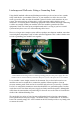
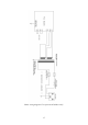
Centre tapped linelumps like the Yamaha PA-20 will have three wires coming from their
connector. It will have two AC outputs and one 0V. Take one of the AC outputs to terminal
AC1 and the other AC output to terminal AC2. It should not matter which AC output goes to
AC1 or AC2. The 0V should go to the 0V2 terminal. The 0V1 terminal is left unused.
Figure 2. Linelump wiring with centre tapped output, eg. Yamaha PA-20
The front panel switch is a double pole single throw (DPST) switch which connects S2R and
S2S together, and S1R and S1S together, when switched on. You can replace the switch with
two wire links, but I do recommend that a switch be fitted so the socket doesn't have to take
the full surge current when you insert it if the linelump is powered up.
I also recommend fitting the AC indicator LED too. This is so you know the linelump is on.
The AC indicator is designed to indicate the status of incoming power and is not determined
by the position of the standby switch.
The standby switch should not be used to turn the unit off permanently. This should be done
by either switching the adapter off at the mains socket, or by pulling the adapter's plug out of
the mains socket.
An optional earth or grounding connection can be made. See next section for more details.
11