MIXING CONSOLE Owner’s Manual Mode d’emploi Bedienungsanleitung M
FCC INFORMATION (U.S.A.) 1. IMPORTANT NOTICE: DO NOT MODIFY THIS UNIT! This product, when installed as indicated in the instructions contained in this manual, meets FCC requirements. Modifications not expressly approved by Yamaha may void your authority, granted by the FCC, to use the product. 2. IMPORTANT: When connecting this product to accessories and/or another product use only high quality shielded cables. Cable/s supplied with this product MUST be used. Follow all installation instructions.
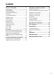
Contents Features of the system...............................5 About the Scene Memory function ........... 31 Control panel............................................6 What is scene memory? ...........................................31 About the modes of the Scene Memory function..31 Operations in normal mode....................................32 Operations in check mode ......................................33 Operations in utility mode......................................34 Utility items............
Precautions • Connect the mixer power cord only to the power supply unit, and connect the power supply unit to an AC outlet of the type stated in this Owner’s Manual or as marked on the power supply unit. Failure to do so is a fire and electrical shock hazard. • Do not locate the mixer in a place subject to excessive heat or in direct sunlight. This could be a fire hazard. • Do not place the mixer in a place subject to excessive humidity or dust. This could be a fire and electrical shock hazard.
Features of the system • The M3000-40C provides a generous number of input modules; 40 monaural and 4 stereo (the M3000-24 provides 24 monaural and 4 stereo). Stereo output, 16 mix outputs, and 8 matrix outputs are provided in addition. The M3000 is suitable for use in a wide range of applications, such as the main mixer for sound reinforcement, as a monitor mixer, or in building installations.
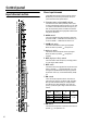
Control panel Input channel section Mono input channels The M3000-24 provides 24 input channels, and the M3000-40C provides 40 input channels. All input channels have the same specifications. +48V 1 2 3 4 5 6 A Phantom power switch/+48 V indicator GAIN –16 –60 26dB Ø 50 150 20 400 HPF HI 3k 8k 1k –15 8k –15 +15 240 1.6k –15 +15 90 P J P L P D ø(phase) switch This switch reverses the phase of the input signal. When the switch is pressed ( ), the phase is reversed.
Control panel I M1–M8 switches M M13/M14, M15/M16 switches These switch on/off the signal which is sent from the input channel to MIX buses 1–8. These are on/off switches for the signals that are sent from the input channel to MIX buses 13–16. M13 and 14, and M15 and M16 are stereo pairs, and each pair is turned on/off by one switch. Use the PRE switch (P) to switch between pre/post fader.
Control panel Q ST (stereo) switch R L PAN ST Q ON/ EDIT S R When this switch is on, the signal of the input channel will be sent to the (ST) stereo bus. CHECK ON PEAK T NOM SIGNAL R PAN control This sets the panning of the signal that is sent from the input channel to the ST bus. S ON/EDIT switch/ON, CHECK indicators The function of this switch and these indicators will depend on the mode of the M3000.
Control panel U VCA GROUP select switches V Channel fader These switches select the VCA master fader(s) which will control the signal output level of this channel. When you select a VCA group 1–8, the indicator located at the left of each switch will light, and the corresponding VCA master fader (VCA master section 3) will control the channel. It is possible to select two or more VCA groups for one input channel, or to control two or more input channels by the same VCA group.
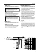
Control panel Stereo input channels A The M3000 provides four stereo input channels. Stereo sound sources such as sub-mixers, effect processor, or CD players can be input to the INPUT A jacks (XLR connectors) or INPUT B jacks (RCA phono connectors) located on the rear panel. GAIN A +10 B C –30 B +10 –20 A B A GAIN A control This control adjusts the input sensitivity of the signal that is input from the XLR connector INPUT A jack (rear panel 4). The level range is +10~ –30 dB.
Control panel G M1–M8 mix level controls J M13/M14, M15/M16 switches These controls combine the stereo signal from the stereo input channel into a mono signal, and send it to MIX buses 1–8. When the control is in the “▲” position, the level is nominal (0 dB). Use the PRE switch (M) to switch between pre/post fader.
Control panel O L BAL ST R N CHECK ON ON/ EDIT PEAK P Q NOM SIGNAL Q PEAK/NOM/SIGNAL indicators Three indicators show the level of the stereo input channel signal after it passes through the EQ. • PEAK indicator This will light when the sum of the L and R signals exceeds the nominal level by 18 dB. • NOM (nominal) indicator This will light when the sum of the L and R signals reaches nominal level (0 dB).
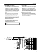
Control panel A Variable/fixed select switches Variable/fixed select section These switches select whether the level of the signals sent from the input channels to MIX buses 1–8 will be fixed (FIX) or variable (VARIABLE). From top to bottom, these switch MIX buses 1/2, 3/4, 5/6 and 7/8. The M3000’s GA (Group/Aux) diversity function allows MIX buses 1–8 to function either as group buses or as AUX buses.
Control panel D ON/EDIT switches Mix section The function of these switches and indicators will depend on the mode of the M3000. These output channels control the signals of MIX buses 1–16. MIX buses 13/14 and 15/16 are controlled as stereo pairs respectively. The signal that passes through these output channels is output individually from the MIX OUT 1–16 jacks (page 27), and can also be sent to the MAS AFL bus, MAS PFL bus, ST bus, and the matrix.
Control panel MIX buses 1–8 1 3 2 5 4 MIX MIX (VARIABLE) (FIX) 7 9 11 13 15 1 2 3 4 5 6 7 8 6 8 10 12 14 16 ST LR TO MATRIX (MIX) (SUB)(ST) LR LR 7 9 11 13 15 8 10 12 14 16 MAS MAS AFL AFL PFL L R L R ON 6 TO MATRIX (MIX) (SUB)(ST) LR LR 7 9 11 13 15 8 10 12 14 16 MAS MAS AFL AFL PFL L R L R ON 6 TO MATRIX (MIX) (SUB)(ST) LR LR 7 9 11 13 15 6 8 10 12 14 16 MAS MAS AFL AFL PFL L R L R ON from INPUT MIX INSERT I/O to Meter 1 3 2 5 4 MIX OUT 1 CHECK ON TO MATRIX from Ctrl Master CONTROL PA
Control panel VCA master fader section The VCA master fader section allows the gain of input channels assigned to a VCA group to be controlled as a whole by the corresponding VCA fader. The VCA group(s) to which each input channel is assigned is specified by the VCA GROUP select switches (mono input channels (U), stereo input channels R).
Control panel A TO MATRIX switch A TO MATRIX When this switch is on ( ), the ST OUT A postfader signal is sent to the matrix. B ON/EDIT switch The function of this switch and indicator will depend on the mode of the M3000. ●In normal mode The ON/EDIT switch will turn ST OUT A on/off. When on, the ON indicator will light. When off, no signal will be sent to the ST OUT A jacks, MONITOR OUT jacks, PHONES jack, MAS AFL bus, or the matrix.
Control panel B ON switch STEREO B section This is an on/off switch for the signal which is output from the ST OUT B jacks. It does not affect the signal which is output from the ST OUT A jacks. When this switch is turned off, the indicator will go dark, and no signal will be output from the ST OUT B jacks. However even in this case, the signal sourced before passing through the LEVEL control can be monitored from the MONITOR OUT jacks or the PHONES jack by turning on the AFL switch (3).
Control panel A INPUT indicator Monitor section A C D This indicator will light if even one of the input channel PFL switches are turned on. INPUT B MASTER B MASTER indicator This indicator will light if even one of the AFL switches of the mix section, STEREO A section, STEREO B section, or matrix section (page 24) are turned on.
Control panel G LEVEL control G This control adjusts the level of the signal which is output from the MONITOR OUT jacks. It does not affect the PHONES jack. 0 H ON switch 10 LEVEL This is an on/off switch for the signal which is output from the MONITOR OUT jacks. When this is on, the indicator located above the switch will light. This switch does not affect the PHONES jack.
Control panel H OSCILLATOR select switch Talkback section A B C D E F G These switches select the type of test oscillator, and begin oscillation. Only one can be selected at a time. The corresponding indicator will light to indicate the switch which is currently on. ●PINK switch Pink noise will be produced. M1-M2 M3-M4 ●10 kHz/1 kHz/100 Hz switches A sine wave of the corresponding frequency will be produced. M5-M6 M7-M8 M9-M12 Note: The oscillator cannot be used in conjunction with talkback.
Control panel Meter select section In this section you can select the source whose level will be shown in the meter bridge section. Only one of the sources 1–3 can be selected. A B C M1-M8 Scene memory section On the M3000, on/off settings for the mono/stereo input channels, the output channels of the mix sections, and STEREO A OUT can be stored as a “scene” (memory numbers 1–128 can be rewritten, and 129– 130 are read-only). In this section you can save and read scene memories.
Control panel G ▲/▼ switches A UTILITY switch Press this switch to enter Utility mode, where you can make settings for scene memories and MIDI, etc. When you are in Utility mode, the indicator located above the switch will light. B RECALL switch Use this switch to recall scenes from scene memory. If you select a scene which has not been stored and attempt to recall it, the MEMORY display (3) will indicate “ ” (No data) for approximately two seconds. C MEMORY display This is a three-digit LED display.
Control panel Matrix section The M3000 provides eight matrices which allow output signals from the MIX buses 1–16 or the ST bus, or input signals from MATRIX SUB IN to be mixed at the desired level. Matrix 1–8 are output in mono from MATRIX OUT jacks 1-8 respectively (page 27), and can be used as foldback or for an individual monitor system.
Control panel Meter bridge B A 20 – 10 PEAK 2 7 5 3 1 0 1 2 VU M1/M9/MATRIX 1 PEAK 3 20 + – 10 7 M2/ 2 3 20 + – IX 7 10 PEAK 2 7 5 3 1 0 1 2 VU 3 20 + – M8/M16/MATRIX 8 10 PEAK 2 7 5 3 1 0 1 2 VU L C 3 20 + – STEREO A 10 PEAK 2 7 5 3 1 0 1 2 VU R 3 20 + – 10 PEAK 2 7 5 3 1 0 1 2 VU L 3 20 + – STEREO B/CUE 10 PEAK 2 7 5 3 1 0 1 2 3 VU + R A M1/M9/MATRIX1–M8/M16/MATRIX8 level meters As selected by the switch settings of the METER SEL section (page 22)
Rear panel Mono input channel input/output jacks Stereo input channel input/output jacks INSERT INSERT OUT IN OUT IN H3 ST CH 2 ST CH 1 TA INPUT A INPUT A L 24 INPUT L 23 22 INPUT INPUT 21 INPU 4 3 NPUT 2 INPUT 1 INPUT ST CH 2 ST CH 1 INPUT A INPUT A INPUT A L L L L R R R R 4 R DIRECT OUT DIRECT OUT DIRECT OUT DIRECT 0 dB TB ST CH 3 INPUT A INPUT A R ST CH 4 L L R R INPUT B INPUT B 0 dB 0 dB ECT OUT DIRECT OUT DIRECT OUT DIRECT OUT 0 dB INSERT I/O I
Rear panel Master section input/output jacks Q N M L R MIDI CONTROL MONITOR ST OUT+4dB OUT+4dB L L I MATRIX OUT+4dB MIX OUT +4dB L 5 1 13 9 5 1 R 6 2 14 10 6 2 L 7 3 15 11 7 3 1+4dB ST INSERT I/O 0dB MIX INSERT I/O 0dB A R OUT R VCA EXTERNAL I/O MASTER SLAVE VCA MASTER/SLAVE MATRIX SUB IN 2–10dBV L R +4dB L 16 15 14 13 12 16 4 8 R R DC POWER INPUT +4dB B CUE CONTROL 12 11 10 9 4 8 8 7 6 5 4 3 2 1 +4dB CUE SUB IN ST SUB IN MIX SUB IN +
Rear panel L ST OUT A/B jacks P CUE SUB IN jacks These are XLR output jacks (balanced) for outputting the signals from the STEREO A/B sections. Nominal output level is +4 dB for both sections. Pin wiring is as follows. Female XLR plug These are 1/4" phone jacks (unbalanced) for mixing the signal from an external device into the PFL bus. Nominal input level is +4 dB. Pin wiring is as follows.
Rear panel U MIDI IN/OUT/THRU connectors These are standard five-pin MIDI connectors. By connecting a sequencer or personal computer to these connectors, you can select scenes remotely, or backup scene memories. If two or more M3000 consoles are connected via MIDI, a scene selection on one M3000 can simultaneously switch the scene on the other M3000(s). Output connector for illumination power supply ●MIDI IN connector MIDI messages are received at this connector.
About the GA Diversity functionality The GA Diversity functionality of the M3000 allows you to switch the MIX buses 1–8 between acting as group buses (output level from the input channels will be fixed) or acting as AUX buses (output level from the input channels will be variable).
About the Scene Memory function What is scene memory? Scene memory is a function which stores the on/off status of the mono/stereo input channels and of MIX buses 1–12, 13/14, 15/16 and ST A as one of 128 “scenes.” A scene that has been stored can be recalled instantly at a touch of a switch. It is also possible to select scenes remotely from an external device connected to the M3000’s MIDI IN, or conversely to transmit a scene recall operation from the MIDI OUT connector as a MIDI program change message.
About the Scene Memory function Operations in normal mode Storing a scene (normal mode) 1. Make sure that the M3000 is in normal mode, and use the ON/EDIT switches of the mono/stereo input channels, the mix section and the STEREO A section to make the desired on/off settings. Note: In normal mode, operation of all ON/EDIT switches will affect the signal which is actually output.
About the Scene Memory function Operations in check mode In check mode you can verify the settings of a scene before recalling it, or edit the on/off status of the ON/ EDIT keys without affecting the internal audio signals. To move from normal mode to check mode, press the CHECK switch in the scene memory section. Verifying a scene before you recall (Check mode) 1. If the M3000 is in normal mode, press the scene memory section CHECK switch.
About the Scene Memory function Operations in utility mode In utility mode you can modify various settings related to scene memory operations. Operations such as Bulk Out and Bulk Dump Request are also performed in this mode. Basic operation in utility mode 1. When the M3000 is in normal mode, press and immediately release the scene memory section UTILITY switch. The UTILITY switch indicator will light, and the M3000 will enter utility mode.
About the Scene Memory function responding program change message will be transmitted. If this is set to “ ” (local), the corresponding program change will be transmitted even when you select a scene for which data has not been saved, thus allowing you to select programs on an external device. (control change transmission/reception) ....................................................... oFF/GrP/on This specifies whether or not control change messages will be transmitted and received via MIDI IN/OUT.
About the Scene Memory function Control No. ON/EDIT Switch 60 Control No.
About the Scene Memory function 6. If you wish to defeat a mute group, press the corresponding DIRECT RECALL 1–8 switch. The mute group will be canceled. Mute group 1 (scene memory number 1) CHECK CHECK CHECK CHECK CHECK ON ON ON ON ON ON/ EDIT ON/ EDIT MUTE (OFF) ON/ EDIT ON ON ON/ EDIT ON/ EDIT MUTE (OFF) Note: ON • The mute settings used in a mute group are the same as the on/off settings of the scenes stored in memory numbers 1–8.
About the VCA functionality The VCA master section of the M3000 contains eight VCA master faders. These VCA master faders 1–8 can be used to control the overall input level of input channels assigned to the corresponding VCA groups 1–8.
About the VCA functionality Using two or more VCA master faders to control a single channel As the opposite of the example on the previous page, it is also possible to assign a channel to two or more VCA groups. The following diagram shows an example of signal flow when channel 1 is assigned to VCA groups 1, 5, and 8.
About the VCA functionality • If the VCA MUTE switch of a VCA master fader is turned on (the indicator beside the switch will light), the post-fader signal of all input channels assigned to that VCA group will be muted. This is convenient when you wish to simultaneously mute or un-mute multiple channels without operating the faders. • By using this in conjunction with the Scene Memory function, you can also mute only specific inputs within a VCA group.
Error messages One of the following error messages may appear in the MEMORY display while operating the M3000 or when the power is turned on. If this occurs, refer to the following explanations and take the appropriate action. An error occurred while receiving MIDI data. If an error occurs while received MIDI data, this error message will be displayed for several seconds. The internal battery voltage has fallen below 2.5V or is an abnormal value (in this case the display will indicate “ ”).
Specifications General specifications 0 dB is referenced to 0.775 Vrms. Total Harmonic Distortion (Master output) Less than 0.1% (THD+N) 20 Hz–20 kHz @ +14 dB 600 Ω Less than 0.05%(2nd-10th) 20 Hz–20 kHz @ +14 dB 600 Ω Frequency Response (Master Output) 0+1, –3 dB 20 Hz–20 kHz @ +4 dB 600 Ω Hum & Noise (20 Hz–20 kHz)*1 –128 dB Equivalent Input Noise. Rs = 150 Ω Input Gain = Max. –99 dB Residual Output Noise.
Specifications Input/output characteristics Input specifications Connection PAD Gain Trim Actual Load Impedance For Use With Nominal 3 kΩ 50-600 Ω Mics & 600 Ω Lines 0 CH INPUT (1~24) (1~40) –60 26 0 –16 26 –30 ST CH A INPUT [L, R] (1~4) +10 ST CH B INPUT [L, R] (1~4) +10 600 Ω Lines 5 kΩ –20 600 Ω Lines 10 kΩ TALKBACK IN 10 kΩ 50-600 Ω Mics 2TR IN 1 [L, R] 2TR IN 2 [L, R] 10 kΩ 600 Ω Lines CUE SUB IN [L, R] MATRIX SUB IN [L, R] Connector In Mixer Sensitivity *6 Nominal Max before
Specifications Other Connector wiring DC POWER INPUT Pin No. Signal name 1 Power supply remote 2 +15 V 3 ±15 V GND 4 +48 V GND 5 –15 V 6 +12 V 7 +12V GND/ power supply remote 8 Power supply remote 9 +48 V 10 FRAME GND 3 7 2 1 6 5 10 9 8 VCA EXTERNAL I/O Pin No.
Dimensions W: 2043/40ch D: 874 H: 265 W: 1515/24ch Units: mm 45
MIDI data format 1. MIDI Channel The same channel is used for transmission and reception. Select from channel numbers 1–16. 2. MIDI Program Change Program change numbers 0–127 correspond to Scene Memory numbers 1–128. This correspondence cannot be changed. However when Mute Group is selected, program change numbers 0–7 cannot be transmitted or received. (Since memory numbers 1–8 will not correspond to program change numbers 0– 7.) In the case of OMNI [on], program changes of all MIDI channels are received.
M YAMAHA [MIXING CONSOLE] Model : M3000 MIDI Implementation Chart Function... IDI Implementation Basic Default Chart Changed Channel Date:Apl/08, 1998 Version : 1.
YAMAHA CORPORATION V302330 R2 1 AP 148 NP Printed in Taiwan Pro Audio Division, #18/3 P.O.