63B-9-1E Hyoshi 4/25/05 9:39 AM Page 1 40 50 OWNER’S MANUAL U.S.A.
63B-9-1E Hyoshi 4/25/05 9:39 AM Page 2 EMU25060 ZMU01690 Read this owner’s manual carefully before operating your outboard motor.
✩✦✯ ✬ ✤✲ ✲✣ ✤ Important manual information EMU31280 To the owner Thank you for choosing a Yamaha outboard motor. This Owner’s Manual contains information needed for proper operation, maintenance and care. A thorough understanding of these simple instructions will help you obtain maximum enjoyment from your new Yamaha. If you have any question about the operation or maintenance of your outboard motor, please consult a Yamaha dealer.
✩✦✯ ✬ ✤✲ ✲✣ ✤ Table of contents General information .......................... 1 Identification numbers record........... 1 Outboard motor serial number .......... 1 Key number....................................... 1 Emission control information ............ 1 North American models..................... 1 Safety information ............................ 2 Important labels................................ 3 Warning labels ..................................
✩✦✯ ✬ ✤✲ ✲✣ ✥ Table of contents models .......................................... 33 Shifting ........................................... 33 Forward (tiller handle and remote control models) ............................. 33 Reverse (automatic reverse lock and power trim and tilt models)..... 34 Stopping engine ............................. 34 Procedure ....................................... 35 Trimming outboard motor............... 35 Adjusting trim angle .......................
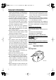
✩✦✯ ✬ ✤✲ ✲✣ ✤ General information EMU25170 Identification numbers record reference in case you need a new key. EMU25182 Outboard motor serial number The outboard motor serial number is stamped on the label attached to the port side of the clamp bracket or the upper part of the swivel bracket. Record your outboard motor serial number in the spaces provided to assist you in ordering spare parts from your Yamaha dealer or for reference in case your outboard motor is stolen. 1.
✩✦✯ ✬ ✤✲ ✲✣ ✥ General information ● EMISSION CONTROL INFORMATION ENGINE FAMILY : THIS ENGINE CONFORMS TO 2001 U.S. EPA REGULATIONS FOR MARINE SI ENGINES. REFER TO THE OWNERS MANUAL FOR MAINTENANCE SPECIFICATIONS AND ADJUSTMENTS.
✩✦✯ ✬ ✤✲ ✲✣ ✦ General information ● ● ● ● ● ● ● ● ● ● ● 3 clude nausea, dizziness, and drowsiness. Keep cockpit and cabin areas well ventilated. Avoid blocking exhaust outlets. Check throttle, shift, and steering for proper operation before starting the engine. Attach the engine stop switch lanyard cord to a secure place on your clothing, or your arm or leg while operating. If you accidentally leave the helm, the cord will pull from the switch, stopping the engine.
✩✦✯ ✬ ✤✲ ✲✣ ✧ General information EMU25401 Label EWM01260 WARNING ● ● ● Be sure shift control is in neutral before starting engine. (except 2HP) Do not touch or remove electrical parts when starting or during operation. Keep hands, hair, and clothes away from flywheel and other rotating parts while engine is running.
✩✦✯ ✬ ✤✲ ✲✣ General information sel head-on) Crossing: (you are traveling across the other vessel’s path) Overtaking: (you are passing or being passed by another vessel) In the following illustration, your boat is in the center. You should give the right-of-way to any vessels shown in white area (you are the Give-Way vessel). Any vessels in the shaded area must yield to you (they are the GiveWay vessels). Both you and the meeting vessel must alter course to avoid each other.
✩✦✯ ✬ ✤✲ ✲✣ ✩ General information bend that may obstruct the view of other water vessels, the operator should sound a prolonged blast on the whistle (4 to 6 seconds). If another vessel is around the bend, it too should sound the whistle. Even if no reply is heard, however, the vessel should still proceed around the bend with caution. If you navigate such waters with your boat, you will need to carry a portable air horn, available from local marine supply stores.
✩✦✯ ✬ ✤✲ ✲✣ ✪ General information ZMU01708 EMU25540 Fueling instructions EWM00010 WARNING GASOLINE AND ITS VAPORS ARE HIGHLY FLAMMABLE AND EXPLOSIVE! ● Do not smoke when refueling, and keep 7 ● ● ● away from sparks, flames, or other sources of ignition. Stop engine before refueling. Refuel in a well-ventilated area. Refuel portable fuel tanks off the boat. Take care not to spill gasoline.
✩✦✯ ✬ ✤✲ ✲✣ ✫ General information ● ● ● ● ● dry rags. Do not overfill the fuel tank. Tighten the filler cap securely after refueling. If you should swallow some gasoline, inhale a lot of gasoline vapor, or get gasoline in your eyes, get immediate medical attention. If any gasoline spills onto your skin, immediately wash with soap and water. Change clothing if gasoline spills on it. Touch the fuel nozzle to the filler opening or funnel to help prevent electrostatic sparks.
✩✦✯ ✬ ✤✲ ✲✣ ✬ General information speed is too high or too low for good engine performance, this will have an adverse effect on the engine. Yamaha outboard motors are fitted with propellers chosen to perform well over a range of applications, but there may be uses where a propeller with a different pitch would be more appropriate. For a greater operating load, a smaller-pitch propeller is more suitable as it enables the correct engine speed to be maintained.
✩✦✯ ✬ ✤✲ ✲✣ ✤✣ Basic components EMU25796 Main components NOTE: * May not be exactly as shown; also may not be included as standard equipment on all models. 40, 50 11 10 9 8 1 12 13 14 15 7 2 6 5 4 3 2 ZMU05014 1. Battery cable 2. Anode(s) 3. Propeller* 4. Cooling water inlet 5. Trim tab (anode) 6. Anti-cavitation plate 7. Trim rod 8. Clamp bracket 9. Tilt support lever 10. Top cowling 11. Remote control box (side mount type)* 12. Digital tachometer* 13. Tachometer* 14.
✩✦✯ ✬ ✤✲ ✲✣ ✤✤ Basic components tions. 1 3 4 2 ZMU03157 1. Fuel joint 2. Fuel gauge 3. Fuel tank cap 4. Air vent screw EMU25830 Fuel joint 1. Power trim and tilt switch 2. Remote control lever 3. Neutral interlock trigger 4. Neutral throttle lever 5. Main switch / choke switch 6. Engine stop lanyard switch 7. Throttle friction adjuster EMU26190 This joint is used to connect the fuel line.
✩✦✯ ✬ ✤✲ ✲✣ ✤✥ Basic components 6. Throttle 7. Fully open EMU26201 Neutral interlock trigger To shift out of neutral, first pull the neutral interlock trigger up. 1. Fully open 2. Fully closed EMU25911 Tiller handle To change direction, move the tiller handle to the left or right as necessary. 1.
✩✦✯ ✬ ✤✲ ✲✣ ✤✦ Basic components 1. Forward “ ” 2. Neutral “ ” 1. Throttle indicator EMU25970 3. Reverse “ ” EMU25941 Throttle grip The throttle grip is on the tiller handle. Turn the grip counterclockwise to increase speed and clockwise to decrease speed. Throttle friction adjuster A friction device provides adjustable resistance to movement of the throttle grip or the remote control lever, and can be set according to operator preference.
✩✦✯ ✬ ✤✲ ✲✣ ✤✧ Basic components NOTE: The engine cannot be started with the lock plate removed. When constant speed is desired, tighten the adjuster to maintain the desired throttle setting. EMU25990 Engine stop lanyard switch The lock plate must be attached to the engine stop switch for the engine to run. The lanyard should be attached to a secure place on the operator’s clothing, or arm or leg.
✩✦✯ ✬ ✤✲ ✲✣ ✤ Basic components EMU26090 EMU26141 Main switch Power trim and tilt switch on remote control or tiller handle The main switch controls the ignition system; its operation is described below. ” (off) ● “ With the main switch in the “ ” (off) position, the electrical circuits are off, and the key can be removed. ● “ ” (on) With the main switch in the “ ” (on) position, the electrical circuits are on, and the key cannot be removed.
✩✦✯ ✬ ✤✲ ✲✣ ✤✩ Basic components UP DOWN ZMU03096 EMU26151 Power trim and tilt switch on bottom engine cowling The power trim and tilt switch is located on the side of the bottom engine cowling. Pressing the switch “ ” (up) trims the outboard motor up, then tilts it up. Pressing the switch “ ” (down) tilts the outboard motor down and trims it down. When the switch is released, the outboard motor will stop in its current position.
✩✦✯ ✬ ✤✲ ✲✣ ✤✪ Basic components A 1 2 B ZMU03097 ZMU03194 EMU26372 1. Trim tab 2. Bolt Top cowling lock lever(s) (turn type) EMU26261 Trim rod (tilt pin) The position of the trim rod determines the minimum trim angle of the outboard motor in relation to the transom. To remove the engine top cowling, turn the lock lever(s) and lift off the cowling. When installing the cowling, check to be sure it fits properly in the rubber seal.
✩✦✯ ✬ ✤✲ ✲✣ ✤✫ Basic components EMU26470 Tachometer This gauge shows the engine speed and has the following functions. 7. Engine trouble warning indicator 8. Set button 9. Mode button NOTE: 1 The water separator and engine trouble warning indicators only operate when the engine is equipped with the appropriate functions. EMU26540 2 ZMU04577 1. Tachometer 2.
✩✦✯ ✬ ✤✲ ✲✣ ✤✬ Basic components rious engine damage will occur. ZMU04581 1 ZMU01867 1. Oil level indicator EMU26581 Overheat warning indicator (digital type) If the engine temperature rises too high, the warning indicator will start to blink. For further information on reading the indicator, see page 20. ECM00050 NOTE: Memorize the trim angles that work best for your boat under different conditions.
✩✦✯ ✬ ✤✲ ✲✣ ✥✣ Basic components engine has been run. It can be set to show the total number of hours or the number of hours for the current trip. The display can also be turned on and off. Activation of warning device The engine speed will automatically decrease to about 2000 r/min.
✩✦✯ ✬ ✤✲ ✲✣ ✥✤ Basic components ZMU03942 ZMU03026 ● EMU26845 Oil level warning and oil filter clogging warning The buzzer will sound (if equipped on the tiller handle, remote control box, or main switch panel). Oil injection models This engine has an oil level warning system. If the oil level falls below the lower limit, the warning system will activate. Activation of warning device ● Engine speed will automatically decrease to about 2000 r/min.
✩✦✯ ✬ ✤✲ ✲✣ ✥✥ Basic components 1 ZMU03366 1.
✩✦✯ ✬ ✤✲ ✲✣ ✥✦ Operation EMU26901 Installation ECM00110 CAUTION: Incorrect engine height or obstructions to smooth water flow (such as the design or condition of the boat, or accessories such as transom ladders or depth finder transducers) can create airborne water spray while the boat is cruising. Severe engine damage may result if the motor is operated continuously in the presence of airborne water spray.
✩✦✯ ✬ ✤✲ ✲✣ ✥✧ Operation motor greatly affects the water resistance. If the mounting height is too high, cavitation tends to occur, thus reducing the propulsion; and if the propeller tips cut the air, the engine speed will rise abnormally and cause the engine to overheat. If the mounting height is too low, the water resistance will increase and thereby reduce engine efficiency. Mount the outboard motor so that the anti-cavitation plate is in alignment with the bottom of the boat.
✩✦✯ ✬ ✤✲ ✲✣ ✥ Operation board (if packed). For details, consult your Yamaha dealer. EWM00650 EMU27060 Gasoline and engine oil mixing chart (50:1) WARNING Avoid using bolts, nuts or washers other than those contained in the engine packaging. If used, they must be of at least the same quality of material and strength and must be tightened securely. After tightening, test run the engine and check their tightness. 1. : Gasoline 2.
✩✦✯ ✬ ✤✲ ✲✣ ✥✩ Operation 4. 5. cool. Third through tenth hours: Avoid operating at full throttle for more than 5 minutes at a time. Let the engine cool between full-throttle runs. Vary engine speed occasionally. After the first 10 hours: Operate the engine normally. Use only straight gasoline in the fuel tank. The Yamaha oil injection system provides proper lubrication for normal operation.
✩✦✯ ✬ ✤✲ ✲✣ ✥✪ Operation ZMU03012 ZMU03367 ECM00130 EMU27270 CAUTION: Ring Free Fuel Additive Be sure to take the above steps when operating the engine after a long period of storage. Otherwise engine seizure could occur. Gasoline is a precise blend of many different substances, each chosen to give certain characteristics. Gasoline blends have been changing in recent years in response to concerns about pollution and resulting emissions regulations.
✩✦✯ ✬ ✤✲ ✲✣ ✥✫ Operation EMU27311 Filling oil for electric start models EWM00530 WARNING Do not add gasoline into the oil tank. Fire or explosion could result. This engine uses the Yamaha oil injection system, which provides superior lubrication by ensuring the proper oil ratio for all operating conditions. No fuel premixing is needed. Simply pour gasoline into the fuel tank and oil into the oil tank. Convenient indicator segments indicate the status of the oil supply.
✩✦✯ ✬ ✤✲ ✲✣ ✥✬ Operation EMU27321 Oil level indicator operation The various functions of the oil level system are as follows: EMU27350 Electric start models Oil level warning indicator (analog tachometer/ bottom cowling) Oil level warning indicator (digital tachometer) Engine oil tank Green Remarks more than 450 cm3 (0.48 US qt, 0.40 Imp qt) Yellow from 450 cm3 (0.48 US qt, 0.40 Imp qt) down to No refilling necessary. Add oil; see page 28. 200 cm3 (0.21 US qt, 0.
✩✦✯ ✬ ✤✲ ✲✣ ✦✣ Operation tank cap, loosen it 2 or 3 turns. zontally, otherwise fuel cannot be drawn from the fuel tank. 4. Squeeze the primer pump with the outlet end up until you feel it become firm. ZMU02295 2. If there is a fuel joint on the motor, firmly connect the fuel line to the joint. Then firmly connect the other end of the fuel line to the joint on the fuel tank. ZMU02025 EMU27490 Starting engine EMU27592 Electric start / prime start models 1.
✩✦✯ ✬ ✤✲ ✲✣ ✦✤ Operation gine stop switch. 4. Turn the main switch to “ ” (start), and hold it for a maximum of 5 seconds. 5. Immediately after the engine starts, release the main switch and allow it to return to “ ” (on). EWM00120 WARNING ● ● ● Attach the engine stop switch lanyard to a secure place on your clothing, or your arm or leg while operating. Do not attach the lanyard to clothing that could tear loose.
✩✦✯ ✬ ✤✲ ✲✣ ✦✥ Operation EMU27662 Electric start and remote control models 1. Place the remote control lever in neutral. 3. 4. Turn the main switch to “ ” (on). Turn the main switch to “ ” (start), and hold it for a maximum of 5 seconds. 5. Immediately after the engine starts, release the main switch and allow it to return to “ ” (on). NOTE: The start-in-gear protection device prevents the engine from starting except when in neutral. 2.
✩✦✯ ✬ ✤✲ ✲✣ ✦✦ Operation again. NOTE: ● ● When the engine is cold, it needs to be warmed up. For further information, see page 33. If the engine is warm and fails to start, open the throttle slightly and try to start the engine again. If the engine still fails to start, see page 60. EMU27670 ZMU03391 EMU27740 Warming up engine EMU27702 Shifting EWM00180 Electric start and prime start models 1. 2. After starting the engine, allow it to idle for 3 minutes to warm up.
✩✦✯ ✬ ✤✲ ✲✣ ✦✧ Operation firmly from neutral to forward. 2. Remote control models 1. Pull up the neutral interlock trigger (if equipped) and move the remote control lever quickly and firmly from neutral to forward. EMU27784 Reverse (automatic reverse lock and power trim and tilt models) Move the gear shift lever quickly and firmly from neutral to reverse. Remote control models 1.
✩✦✯ ✬ ✤✲ ✲✣ ✦ Operation ping the engine immediately after operating at high speed is not recommended. EMU27844 Procedure 1. Push and hold the engine stop button or turn the main switch to “ ” (off). ZMU02301 4. Remove the key if the boat will be left unattended. NOTE: The engine can also be stopped by pulling the lanyard and removing the lock plate from the engine stop switch, then turning the main switch to “ ” (off). EMU27861 Trimming outboard motor 2.
✩✦✯ ✬ ✤✲ ✲✣ ✦✩ Operation Adjust the outboard motor trim angle using the power trim and tilt switch. UP DN 1 ZMU03110 1. Power trim and tilt switch 1 UP ZMU03109 1. Trim operating angle EMU27881 DOWN Adjusting trim angle ZMU03096 Power trim and tilt models EWM00750 WARNING ● ● ● Be sure all people are clear of the outboard motor when adjusting the tilt angle, also be careful not to pinch any body parts between the drive unit and clamp bracket.
✩✦✯ ✬ ✤✲ ✲✣ ✦✪ Operation “ ” (down). Make test runs with the trim set to different angles to find the position that works best for your boat and operating conditions. the operator and passengers overboard. NOTE: To adjust the trim angle while the boat is moving, use the power trim and tilt switch located on the remote control device or tiller handle, if equipped.
✩✦✯ ✬ ✤✲ ✲✣ ✦✫ Operation sion with obstructions, and also to reduce salt corrosion. EWM00220 WARNING Be sure all people are clear of the outboard motor when tilting up and down, also be careful not to pinch any body parts between the drive unit and engine bracket. EWM00250 WARNING Leaking fuel is a fire hazard. If there is a fuel joint on the outboard motor, disconnect the fuel line or close the fuel cock if the engine will be tilted for more than a few minutes.
✩✦✯ ✬ ✤✲ ✲✣ ✦✬ Operation UP UP DN ZMU01935 ZMU03115 EWM00260 WARNING After tilting the outboard motor, be sure to support it with the tilt support knob or tilt support lever. Otherwise the outboard motor could fall back down suddenly if oil in the power trim and tilt unit loses pressure. UP ZMU04993 5. Models equipped with trim rods: Once the outboard motor is supported with the tilt support lever, press the power trim and tilt switch “ ” (down) to retract the trim rods.
✩✦✯ ✬ ✤✲ ✲✣ ✧✣ Operation ZMU02569 3. Push the power tilt / power trim and tilt switch “ ” (down) to lower the outboard motor to the desired position. EMU28060 Cruising in shallow water The outboard motor can be tilted up partially to allow operation in shallow water. EMU28090 DN Power trim and tilt models / power tilt models UP DN The outboard motor can be tilted up partially to allow operation in shallow water.
✩✦✯ ✬ ✤✲ ✲✣ ✧✤ Operation UP ZMU03412 2. Slightly tilt the outboard motor up to the desired position using the power trim / tilt switch. 3. To return the outboard motor to the normal running position, press the power trim / tilt switch and slowly tilt the outboard motor down.
✩✦✯ ✬ ✤✲ ✲✣ ✧✥ Maintenance EMU28217 Specifications Dimension: Overall length: 40TR 646 mm (25.4 in) 50TR 670 mm (26.4 in) Overall width: 40TR 350 mm (13.8 in) 50TR 360 mm (14.2 in) Overall height L: 1319 mm (51.9 in) Transom height L: 533 mm (21.0 in) Weight (without propeller) L: 86.0 kg (190 lb) Performance: Full throttle operating range: 4500–5500 r/min Maximum output: 40TR 29.4 kW@5000 r/min (40 HP@5000 r/min) 50TR 36.
✩✦✯ ✬ ✤✲ ✲✣ ✧✦ Maintenance Spark plug: 25.0 Nm (18.4 ft-lb) (2.55 kgf-m) Propeller nut: 35.0 Nm (25.8 ft-lb) (3.57 kgf-m) EMU28222 Transporting and storing outboard motor EWM00690 sition using a motor support device such as a transom saver bar. Consult your Yamaha dealer for further details. EMU28235 Clamp screw mounting models When transporting or storing the outboard motor while removed from a boat, keep the outboard motor in the attitude shown.
✩✦✯ ✬ ✤✲ ✲✣ ✧✧ Maintenance ventilated place, not in direct sunlight. EMU28301 Procedure EMU28372 Flushing in a test tank 1. Wash the outboard motor body using fresh water. For further information, see page 46. 2. Fill the fuel tank with fresh fuel and add one ounce of “Yamaha Fuel Conditioner and Stabilizer” (Part No. LUB-FUELC12-00) to each gallon of fuel. water pump will be damaged or the engine will be damaged from overheating.
✩✦✯ ✬ ✤✲ ✲✣ ✧ Maintenance cowling. EMU28410 Lubrication (oil injection models) 1. 2. 3. 4. Grease the spark plug threads and install the spark plug(s) and torque to proper specification. For information on spark plug installation, see page 49. Fill the oil tanks. This prevents the formation of condensation. For models with a remote oil tank, it may be necessary to manually override the control unit to completely fill the engine oil tank. Change the gear oil.
✩✦✯ ✬ ✤✲ ✲✣ ✧✩ Maintenance 4. Once a month, check the specific gravity of the electrolyte and recharge as required to prolong battery life. EMU28450 Cleaning the outboard motor After use, wash the exterior of the outboard motor with fresh water. Flush the cooling system with fresh water. tems may be performed by any marine engine repair establishment or individual.
✩✦✯ ✬ ✤✲ ✲✣ ✧✪ Maintenance EMU28522 Maintenance chart Frequency of maintenance operations may be adjusted according to the operating conditions, but the following table gives general guidelines. Refer to the sections in this chapter for explanations of each owner-specific action. NOTE: When operating in salt water, turbid or muddy water, the engine should be flushed with clean water after each use. The “ The “ ” symbol indicates the check-ups which you may carry out yourself.
✩✦✯ ✬ ✤✲ ✲✣ ✧✫ Maintenance Initial Item Actions Water pump Inspection / replacement Oil pump Inspection / adjustment Oil tank water drain Inspection / cleaning Spark plug(s) Cleaning / adjustment / replacement 10 hours (1 month) 50 hours (3 months) Every 100 hours (6 months) 200 hours (1 year) 48
✩✦✯ ✬ ✤✲ ✲✣ ✧✬ Maintenance EMU28931 Greasing Yamaha marine grease (Water resistant grease) 40, 50 ZMU03414 EMU28952 Cleaning and adjusting spark plug EWM00560 WARNING When removing or installing a spark plug, be careful not to damage the insulator. A damaged insulator could allow external sparks, which could lead to explosion or fire. 49 The spark plug is an important engine component and is easy to inspect.
✩✦✯ ✬ ✤✲ ✲✣ ✣ Maintenance Yamaha dealer. You should periodically remove and inspect the spark plug because heat and deposits will cause the spark plug to slowly break down and erode. If electrode erosion becomes excessive, or if carbon and other deposits are excessive, you should replace the spark plug with another of the correct type.
✩✦✯ ✬ ✤✲ ✲✣ ✤ Maintenance ● spilled fuel immediately. The fuel filter must be reassembled carefully with the O-ring, filter cup, and hoses in place. Improper assembly or replacement could result in a fuel leak, which could result in a fire or explosion hazard. EMU29001 Cleaning fuel filter 1. Remove the nut holding the fuel filter assembly if equipped.
✩✦✯ ✬ ✤✲ ✲✣ ✥ Maintenance 2 3 4 on whether testing is conducted with the flushing attachment, in a test tank, or with the outboard motor in the water. 1. Start the engine and allow it to warm up fully in neutral until it is running smoothly. NOTE: 1 ZMU02079 1. Filter cup 2. Filter element 3. Filter housing 4. O-ring 4. 5. 6. Reinstall the filter element in the cup. Make sure the O-ring is in position in the cup. Firmly screw the cup onto the filter housing.
✩✦✯ ✬ ✤✲ ✲✣ ✦ Maintenance curely. 2 1 ZMU03417 ZMU03240 EMU29120 1. Trim and tilt rod 2. Tilt support lever Exhaust leakage Start the engine and check that no exhaust leaks from the joints between the exhaust cover, cylinder head, and body cylinder. 2. EMU29130 Water leakage Start the engine and check that no water leaks from the joints between the exhaust cover, cylinder head, and body cylinder.
✩✦✯ ✬ ✤✲ ✲✣ ✧ Maintenance ● move the key, and remove the lanyard from the engine stop switch. Turn off the battery cut-off switch if your boat has one. Do not use your hand to hold the propeller when loosening or tightening the propeller nut. Put a wood block between the anti-cavitation plate and the propeller to prevent the propeller from turning. ● Check the propeller shaft oil seal for damage.
✩✦✯ ✬ ✤✲ ✲✣ Maintenance 5. Propeller 6. Thrust washer 3. Remove the propeller and thrust washer. NOTE: If the propeller nut does not align with the propeller shaft hole after tightening to the specified torque, tighten the nut further to align it with the hole.
✩✦✯ ✬ ✤✲ ✲✣ ✩ Maintenance the screw before installing it. EMU29302 4. EWM00920 Cleaning fuel tank Remove the oil level plug to allow the oil to drain completely. ECM00710 CAUTION: Inspect the used oil after it has been drained. If the oil is milky, water is getting into the gear case which can cause gear damage. Consult a Yamaha dealer for repair of the lower unit seals. NOTE: For disposal of used oil consult your Yamaha dealer. 5.
✩✦✯ ✬ ✤✲ ✲✣ ✪ Maintenance 5. suction pipe) in a suitable cleaning solvent. Allow the filter to dry. Replace the gasket with a new one. Reinstall the fuel joint assembly and tighten the screws firmly. EMU29312 Inspecting and replacing anode(s) Yamaha outboard motors are protected from corrosion by sacrificial anodes. Inspect the external anodes periodically. Remove scales from the surfaces of the anodes. Consult a Yamaha dealer for replacement of external anodes.
✩✦✯ ✬ ✤✲ ✲✣ ✫ Maintenance followed by milk of magnesia, beaten egg, or vegetable oil. Get immediate medical attention. Batteries also generate explosive hydrogen gas; therefore, you should always follow these preventive measures: ● Charge batteries in a well-ventilated area. ● Keep batteries away from fire, sparks, or open flames (for example: welding equipment, lighted cigarettes, and so on.) ● DO NOT SMOKE when charging or handling batteries.
✩✦✯ ✬ ✤✲ ✲✣ ✬ Maintenance ing paint approved for your area to inhibit marine growth. Do not use anti-fouling paint which includes copper or graphite. These paints can cause more rapid engine corrosion. minal. 1. Red cable 2. Black cable 3. Battery ZMU01943 EMU29370 Disconnecting the battery Disconnect the BLACK cable from the NEGATIVE (-) terminal first. Then disconnect the RED cable from the POSITIVE (+) terminal.
✩✦✯ ✬ ✤✲ ✲✣ ✩✣ Trouble Recovery EMU29424 Troubleshooting A problem in the fuel, compression, or ignition systems can cause poor starting, loss of power, or other problems. This section describes basic checks and possible remedies, and covers all Yamaha outboard motors. Therefore some items may not apply to your model. If your outboard motor requires repair, bring it to your Yamaha dealer. If the engine trouble warning indicator is flashing, consult your Yamaha dealer.
✩✦✯ ✬ ✤✲ ✲✣ ✩✤ Trouble Recovery Q. Is fuel system obstructed? A. Check for pinched or kinked fuel line or other obstructions in fuel system. Q. Is fuel contaminated or stale? A. Fill tank with clean, fresh fuel. Q. Is fuel filter clogged? A. Clean or replace filter. Q. Have ignition parts failed? A. Have serviced by a Yamaha dealer. Q. Has warning system activated? A. Find and correct cause of warning. Q. Is spark plug gap incorrect? A. Inspect and adjust as specified. Q.
✩✦✯ ✬ ✤✲ ✲✣ ✩✥ Trouble Recovery A. Have serviced by a Yamaha dealer. Q. Is load on boat improperly distributed? A. Distribute load to place boat on an even plane. Q. Are weeds or other foreign matter tangled on gear housing? A. Remove foreign matter and clean lower unit. Q. Is water pump or thermostat faulty? A. Have serviced by a Yamaha dealer. Q. Is fuel system obstructed? A. Check for pinched or kinked fuel line or other obstructions in fuel system. Q.
✩✦✯ ✬ ✤✲ ✲✣ ✩✦ Trouble Recovery Q. Is fuel joint connection incorrect? A. Connect correctly. Q. Is heat range of spark plug incorrect? A. Inspect spark plug and replace it with recommended type. damaged by a collision while operating or trailering. Damage could make the outboard motor unsafe to operate. If the outboard motor hits an object in the water, follow the procedure below. Q. Is high pressure fuel pump drive belt broken? A. Have serviced by a Yamaha dealer. Q.
✩✦✯ ✬ ✤✲ ✲✣ ✩✧ Trouble Recovery then tighten the manual valve screw by turning it clockwise. EMU29531 Starter will not operate 1 If the starter mechanism does not operate (the engine cannot be cranked with the starter), the engine can be started with an emergency starter rope. 2 EWM01020 3 WARNING ZMU03421 ● 1. Fuse holder 2. Fuse (20 A) 3. Spare fuse (20 A) ● NOTE: Consult your Yamaha dealer if the new fuse immediately blows again.
✩✦✯ ✬ ✤✲ ✲✣ ✩ Trouble Recovery ● main switch must be “ equipped. wheel or other moving parts when the engine is running. Do not install the starter mechanism or top cowling after the engine is running. Do not touch the ignition coil, spark plug wire, spark plug cap, or other electrical components when starting or operating the motor. You could get an electrical shock. ” (on), if EMU29573 Emergency starting engine 1. 2. ZMU03140 Remove the top cowling.
✩✦✯ ✬ ✤✲ ✲✣ ✩✩ Trouble Recovery NOTE: When the engine does not start with this procedure, see page 66. EMU29670 Engine fails to operate EMU29704 Cold engine fails to start If the engine fails to start when it is cold, use the following procedure. ZMU03142 EWM00410 WARNING 4. When starting or operating the engine, do not touch the ignition coil, spark plug wire, spark plug cap, or other electrical parts carrying high voltage.
✩✦✯ ✬ ✤✲ ✲✣ ✩✪ Trouble Recovery 6. Turn the main switch to “ ” (start). ECM00191 When the starter mechanism malfunctions, see page 64. CAUTION: ● ● NOTE: Never turn the main switch to “ ” (start) while the engine is running. Do not keep the starter motor turning for more than 5 seconds. If the starter motor is turned continuously for more than 5 seconds, the battery will be quickly discharged, thus making it impossible to start the engine. The starter can also be damaged.
✩✦✯ ✬ ✤✲ ✲✣ ✩✫ Trouble Recovery 3. 4. Drain the fuel from the carburetor, fuel filter, and fuel line. Feed fogging oil or engine oil through the carburetor(s) and spark plug holes while cranking with the manual starter or emergency starter rope. ZMU01911 5. Take the outboard motor to a Yamaha dealer as soon as possible. ECM00400 CAUTION: Do not attempt to run the outboard motor until it has been completely inspected.
✩✦✯ ✬ ✤✲ ✲✣ ✩✬ Consumer information EMU29811 Important warranty information for U.S.A.
✩✦✯ ✬ ✤✲ ✲✣ ✪✣ Consumer information 70
✩✦✯ ✬ ✤✲ ✲✣ ✪✤ Consumer information EMU29820 YAMAHA MOTOR CORPORATION, U.S.A.
✩✦✯ ✬ ✤✲ ✲✣ ✪✥ Consumer information 72
✩✦✯ ✬ ✤✲ ✲✣ ✪✦ Consumer information 73
✩✦✯ ✬ ✤✲ ✲✣ ✪✧ Consumer information EMU29841 IMPORTANT WARRANTY INFORMATION IF YOU USE YOUR YAMAHA OUTSIDE THE USA OR CANADA 74
63B-9-1E Hyoshi 4/25/05 9:39 AM Page 4 Printed in Japan May 2005–0.
Warranty card-04 2/17/03 2:41 PM Page 1 OUTBOARD MOTOR WARRANTY REGISTRATION ENREGISTREMENT DE LA GARANTIE DU MOTEUR HORS-BORD Please complete and mail this card. This information is necessary to accurately register your unit for warranty. Veuillez signer ci-dessous pour attester que le montage et l’inspection ont été faits dans le respect des directives d’inspection et que la marche à suivre pour la garantie et l’entretien a été expliquée à l’acheteur au détail.
Warranty card-04 2/17/03 2:41 PM Page 2 PLACE POSTAGE HERE ATTN: WARRANTY DEPARTMENT