980 SRX440 FOREWORD This Service Manual has been written to acquaint the mechanic with the disassembly. reassembly. maintenance. and troubleshooting procedures required to provide optimum performance and longevity of the machine. The information herein should be closely studied to avoid unnecessary repairs and to provide the owner with a sound. safe. dependable machine. NOTE:------------ _ The Research and Engineering Departments of Yamaha are continually striving to further perfect all models.
SECTION INDEX GENERAL ENGINE COOLING SYSTEM CARBURETION POWER TRAIN CHASSIS .
1980 SRX440 CHAPTER 1. GENERAL 1-1. EXTERNALVIEW. 1-2 1-2. MACHINE IDENTIFiCATION 1-3 1-3. 1-4. A. Frame serial number. 1-3 B. Engine serial number 1-3 MAINTENANCE INTERVALS CHARTS 1-4 A. Periodic maintenance 1-4 B.
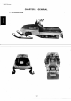
1980 SRX440 CHAPTER 1. GENERAL 1-1.
1980 SRX440 1-2. MACHINE IDENTIFICATION B. Engine serial number The engine serial number is located on the right-hand side of crankcase cover. The prefix indicates engine type and displacement. The prefix is followed by a dash and the SElrial number. Normally both frame and engine serial numbers are identical; however, on occasion they may be two or three numbers off. A. Frame serial number The frame serial number is located on the righthand side of frame (just below the front of seat).
1980 SRX440 Every Check point .. 20 hrs. or 40 hrs. or 400km 800 km (250mi) (500mi) 80 hrs. or 1,600 km (1.000 mil When necessary Seasonally Coolant leakage 0 Operation of thermostat 0 0 Operation of water pump 0 0 Water pump belt tension.
1980 SRX440 B. Lubrication intervals Every Check point 20 hrs. or 40Qkm (250 mil 40 hrs. or 800 km (500 mil 80 hrs. or 1,600 km {1.000mil When necessary Oil/Grease Seasonally Brand name ENGINE: Starter case ..
1980 SRX440 Tool name Tool No. Rotor holding tool 90890-01235 E. Primary sheave Refer to "5-1-8. Primary sheave" 1. Rotor holding tool F. Oil pump 1. Remove the oil delivery pipes. 2. Remove the bolts and pump drive case. 3. Using the flywheel puller, remove the flywheel assembly. No. 4 5 Tool name Tool No.
1980 SRX440 8. Remove engine bracket. 9. Remove crankcase holding bolts.. Each bolt position is numbered, Start with the largest number for disassembly. Loosen each bolt 1/4 turns and proceed to the next. 10. Split crankcase by lightly striking the upper and lower crankcases. 11. Remove crankshaft by tapping the shaft with your hands. 1\10 I E: :~ For thermostat inspection. refer to thermostat. 3-5 2-2. INSPECTION. REASSEMBLY AND ADJUSTMENT A. Engine components 1. Crankcase a.
1980 SRX440 b. Check oil seal lips for damage and wear. Replace as required. Crank bearing Crankshaft oil seal lip Yamalube 2-cycle oil Low temperature grease (Esso Beacon 325 or Aerosheli grease #7 AI 4. Crankshaft inspection a. Check connection rod axial play at small end (to determine. the amount of wear of crank pin and bearing at big end). If small end play exceeds tolerance. disassemble the crankshaft. check connecting rod. crank pin and big end bearmg. Replace defective parts.
1980 SRX440 c. Check crankshaft assembly runout (misalignment of crankshaft parts). Dial gauge readings should be within specification. Correct any misalignment by tapping the flywheel with a brass hammer and/or by using a wedge. Deflection tolerance Left side Center Center (left) (right) 0.03 mm 0.04mm 0.04mm (0.0012 in) (0.0016 in) 10.0016 in) Right side 0.05 mm 10.0020 in) FWD <> 80mm ~ 1. Knock pin 2. Sealing surface 3. Upper case 4.
1980 SRX440 . Tightening torque: 40 Nm (4.0 m-kg) Tightening torque: First: 10 Nm (1.0 m-kg) Final: 22 Nm (2.2 m-kg) 8. Piston pin and bearing inspection a. Check the pin for signs of wear. If any wear is evident. replace pin and bearing. c. After reassembly, apply a liberal coating of two-stroke oil to the crank pin, bearing and into each crankshaft bearing oil delivery hole. b. Check the pin and bearing for signs of heat discoloration. If excessive (indentation on pin, etc.). replace pin and bearIn.
1980 SRX440 e. The piston pin should have no noticeable free play in the piston. If the piston pin is loose, replace the pin and/or piston. e. Wash piston in solvent and wipe dry. f. Measure the outside diameter of the piston at the piston skirt. Measurement should. be made at a point 10 mm (0.5 in) above the bottom edge of the piston. Place the micrometer at right angles to the piston pin.
1980 SRX440 NOTE:-----------Take care during installation to avoid damaging the piston skirts against the crankcase as the cylinder is installed. 12. Cylinder inspection CAUTION: - - ' - - - - - - - - - . . . , This model has a hard chromed cylinder bore. which cannot be honed or bored. a. Remove the carbon deposits from exhaust port. b. Remove the any obstructions from the coolant passages. c. Check cylinder. The cylinder inner wall is plated with hard chrome.
1980 SRX440 2/~' ~/ ---------- ,-------- 3 e. Clean cylinder in solvent, then with hot soapy water. Dry. Coat with light oil film. 13. Cylinder installation a. Install a new cylinder base gasket. b Install cylinder with one hand compressing piston rings with hand. c. Remove any obstructions from the coolant passages. 15, Cylinder head installation Install cylinder head gasket, D-ring and cyiinder head. Working in a crisscross pattern, tighten head nuts in two steps.
1980 SRX440 c. Install the intake manifold. c. Measure the gap with the thickness gauge between the raised boss on the pump adjust pulley and the adjust plate. Tightening torque: 15 Nm (1.5 m-kg) 17. Exhaust pipe installation Remove the carbon deposits from exhaust pipe. Inspect the exhaust gasket for damage and replace it as required. Install the exhaust pipe with gasket. Tightening torque: 23 Nm (2.3 m-kg) 18.
80 SRX440 NOTE:--~------- Recommended grease: Low temperature grease (Esso Beacon 325 or Aeroshell grease #7A) Check the bleed screw gasket. and if damaged. replace with a new one. b. Bleeding the pump distributor and/or delivery pipe. 1) Start the engine. 2) Pull the pump wire all the way out to set the pump stroke to a maximum. Pump case tightening torque: 10Nm(1.0m-kg) 3. Install pump wire, pump case and oil delivery pipe. CAUTION:---------...
1980 SRX440 Tightening torque: 10 Nm (1.0 m-kg) E, Water pump NOTE: - - - - - - - - - - - - For inspection, refer to "3-4 Water pump". 1. Install the water pump assembly temporarily. 1. Play 2. Adjuster 3. Lock nut C. Primary sheave Refer to "5-1 - B. Primary sheave". D. Flywheel magento (For inspection. refer to '7 -1-G. Pulser and charge coil test" and "7-2-C. Lighting circuit test'") 1. Install woodruff key. ------'Tln-sfilTI-f1ywheeTbase:·· 2.
.. _---_._-1980 SRX440 4. By moving the water pump housing up and down, adjust the belt tension. Adjust the bolt so that the belt deflects 4 mm (0.16 in) when a force of 4 kg (9 Ib) is applied to the center of belt. NOTE: - - - - - - - - - - - 1. It is necessary to wind the spring to a small size before installing it in the starter case. 2. Be careful not to install the spring in a wrong way. 3. Hook the loop on the outer end of the spring onto the spring hook in the starter case.
1980 SRX440 1. Drive plate spring 2. Drive pawl 3. Return spring 4. Place the drive pawl, return spring, .l drive plate spring, drive plate and tighten the thrust washer and nut. NOTE:----~------ Grease the pivot of the drive pawl. Tightening torque: 10Nm(1.0m-kg) em y, c ec the starter for smooth operation: Pull out the starter rope about 80 ~ 130 mm (3 ~ 5 in). and make sure that the starter pawl moves out of the drive plate. 6. Install the starter assembly on the. crankcase.
1980 SRX440 WARNING: - - - - - - - - - - - , By turning out the throttle lever 2 or 3 turns, make sure it operates correctly. Intake silencer Manual starter handle NOTE: - - - - - - - - - - , - - - For inspection, see "5-1-C V-bett".', V-belt Tachometer cable Coolant hoses Fuel pipes, pulse pipe CAUTION:----------, The oi I pipe, in which the oi I filter is installed, must be correctly connected to the oil pump. Oil pipes NOTE: - - - - - - - - - - - After installing oil pipe.
r ,.
1980 SRX440 CHAPTER 3. COOLING SYSTEM 3-1. COOLANT Coolant level B. Coolant type C. Draining the coolant D. Replenishing the coolant COOLING SYSTEM CHECK A. Cooling system check B. Radiator cap check RADIATOR A. Removal B. Inspection C. Installation HEAT EXCHANGER A. Removal B, Inspection C. Installation WATER PUMP A. Disassembly B. Inspection C. ReasseM.bly 3-2 3-2 3-2 3-2 3-3 3-3 3-3 3-4 3-4 3-4 3-4 3-4 3-4 3-4 3-4 3-4 3-5 3-5 3-5 3-5 A. 3-2. 3-3. 3-4. 3-5. A. B. C.
1980 SRX440 CHAPTER 3. COOLING SYSTEM 3-1. COOLANT C. Draining coolant 1. When the coolant is still hot, slowly loosen the radiator cap to lower the pressure in the radiator. Take care not to allow the coolant to spout out. 2. Remove the drain bolt on the exhaust side of the cylinder, and let it run into a container so that the cylinder head and cylinder water jackets and radiator are completely drained off. A. Coolant level WARNING:-----------.
1980 SRX440 D. Replenishing coolant 4. After starting the engine, the coolant level will go down. Add coolant while keeping the engine running. 5. When the coolant level in the radiator becomes stable, stop the engine. Loosen (do not remove) the bleeder bolt located above the thermostat va Ive and let the air out. Add coolant to radiator again up to the level line shown in the illustration. 6. Repeat steps 4 and 5 above until the coolant level in the radiator becomes stable. Tighten bleeder bolt. 7.
1980 SRX440 2. Apply 10 bar (1.0 kg/cm 2 ) pressure. and observe the gauge to check whether pressure drops or not. If the pressure shows a drop. the cooling system is leaky. Repair as required. (Refer to "3-3 Radiator" or below.) B. Inspection 1. In very dusty conditions, the radiator tube system should be kept clean by blowing through with compressed air from the engine side. 2. Check the radiator for leakage and damage. Repair as necessary. 3. Check the coolant hoses for cracks and damage.
1980 SRX440D 4. Install the seat and slide rail suspension assembly. (Refer to "5-3 SUSPENSION".) 5. Fill with the coolant. (Refer to "3-2-0 Replenishing coolant:") 3-5. WATER PUMP A. Disassembly 1. Drain the coolant. (Refer to "3-1-C Draining coolant"} 2. Remove the water pump assembly from the engine. (Refer to "2-1-0 Water pump".) 3. Remove the water pump cover. B. Inspection 1. Remove the deposits from the impeller and water pump cover. 2. Check the impeller for cracks and damage.
1980 SRX440 3. Remove the thermostat. 4. Install the impeller. B, Inspection 1. Suspend thermostat in a vessel of water with a reliable thermometer. 2. Heat the water slowly, noting the thermometer reading and stirring the water continually. 3. The thermostat valve should begin to open at 60 ~ 65°C (140 ~ 149° F), Tightening torque: 25 Nm (2.5 m-kg) 5. Coat the mating surfaces of water pump housing and cover with YAMAHA BOND #4, and install a new gasket. 6. Install the water pump cover.
1980 SRX440 2. Install the coolant hose. 3. Inspect the cooling system. (Refer to "3-2-A Cooling system check:") 4. Fill with the coolant.
1980 SRX440D CHAPTER 4. CARBURETION 4-1. 4-2. CARBURETOR A. Carburetor tuning B. Overhauling C. Troubleshooting FUEL PUMP , 4-2 4-2 4-5 .
1980 SRX440 CHAPTER 4. CARBURETION 4-1. CARBURETOR Free play between outer tube end and adjuster: 0.5 ~ 1.0 mm (0.2 ~ 0.4 in) A. Carburetor tuning 1. Standard specification The carburetor is set at the factory to run at temperatures of O°C to - 20°C (32 ° F to - 4 ° F) at sea level. If the machine has to be operated under conditions other than specified above, the carburetor must be reset as required. Special care should be taken in carburetor setting so that pistons will not be holded or seized.
1980 SRX440 3. Starter cable adjustment Pull the starter cable outer tube upward, and adjust the free play between the outer tube end and adjuster to specification by turning the adjuster. After the adjustment, tighten the lock nut and replace the rubber cap to keep the lock nut free from dust and water. a. Tighten the pilot screw lightly, and back it out from its lightly seated position. Standard pilot screw (turns out): 2.
1980 SRX440D Spare pilot jet: 2. Turn the pilot screw in and out 1/4 turn or less each time, and set it in a position where the engine idles faster. 3. Follow step C in the preceding paragraph. #90, #80 6. Main circuit tuning No adjustment is normally required, but adjustment is sometimes necessary depending on temperatures and/or altitude. (Refer to Jet setting chart.) 1.
1980 SRX440 Bad (Due to lean a mixture. the spark pluq melts.) No.6 Check the piston for holes or seizure. Check the cooling system, gasoline octane rating and ignition timing. After replacing the spark plug with colder type, tune the carburetor again. starting with low-speed tuning. 1. Throttle cable 2. Pump cable 3. Starter cable CAUTION: - - - - - - - - - , When removing the starter cable, take care so that the rubber cap, coil spring and starter cable do not fall off or are not lost.
1980 SRX440 NOTE:-----------1. Hook the clip onto the float arm. and remove the fuel valve while taking care not to drop it . .2. The fuel valve plays a very important role. so special care should be taken so that the rubber part of the needle is not scratched. 3. Use care to keep the plastic parts free from shocks. because they could be . damaged easily. 4. Never wash the rubber parts with alcohol or lacquer thinner. Use gasoline.
1980 SRX440 2. Inspection CAUTION: - - - - - - - - - - , Never attempt to disassemble the following parts. 1) Throttle valve 2) Throttle shaft Reason: 1) The threaded portion of the screw is clinched after the throttle valve is installed to the throttle shaft so that the screw will not come loose. 2) The bypass hole is precrsronmachined so that the correct distance can be maintained from the end of the throttle valve.
1980 SRX440 a. Float chamber 1) Check the starter jet and power jet circuits for clogging with dust. If clogged. blow them off with compressed air. 3) Check the starter circuit for clogging with dust. If clogged, blow if off with compressed air. NOTE: -------~_-~- If the starter circuit is clogged, fuel flow will be hindered and hard starting will result. 4) Blow the air bent and slow circuits with compressed air. 1.
1980 SRX440 NOTE: - - - - - - - - - - - - The pilot screw must not be tightened excessively. 51 Install the valve seat. Tightening torque: 5 Nm (0.5 m-kg) 6) Put the valve needle into the valve seat. NOTE: - - - - ' - - - - - - - - - - After assembling. take care not to allow dust and dirt to enter. 3. Reassembly and adjustment CAUTION:-----------, 1) Wash all parts in clean gasoline be- fore assembling. 7) Float level (1) Reinstall components. except for 2) Always use new a-rings.
1980 SRX440 (4) If any part is in good condition but float level is not within the specified range, correct float level by bending the float arm tang slightly. r:CAUTION: (Always use a new O-ring for reassembly. I c. Push the carburetor into the rubber joint, and secure it with the band. 1) Before installing the carburetor on the engine, connect the control cables in the reverse order of disconnection. Keep the starter valve free from dust and dirt during this operation.
1980 SRX440 carburetor with a hard tool. Dust should be blown off with compressed air. 2) When reinstalling the throttle cable, make su re the th rottle va Ive can be fully opened and closed, and make an adjustment. Trouble Check point Hard starting Remedy Insufficient fuel Add gasoline Excessive use of starter Clean spark plug (Excessively opened choke) Fuel passage is clogged or frozen frozen Adjustment Return starter lever to its home position.
1980 SRX440 Trouble Abnormal combustion (Mainly backfire) Overflow (Relative troubles) Power idleing Clogged power jet Clean Clogged fuel pipe Clean or replace Dirty fuel tank Clean fuel tank Air leaking into fuel line Check joint and retighten low fuel pump performance Repair pump or replace Clogged fuel filter Replace Clogged silencer outlet Check for ice.
1980 SRX440 CHAPTER 5. POWER TRAIN 5-1. 5-2. 5-3. 5-4. DRIVE 5-2 A. Sheave adjustment 5-2 B. Primary sheave C. V-belt.. 5-7 D. Secondary sheave 5-7 E. Chain housing 5-9 F. Front axle : 5-3 5-13 BRAKE 5-15 A. Disassembly 5-15 B. Inspection 5-15 C. Reassembly 5-16 D. Adjustment. 5-16 SUSPENSION 5-16 A. Removal.............................................................................................................. -16 B. Inspection : 5-17 C.
1980 SRX440 CHAPTER 5. POWER TRAIN If any of these is incorrect. proceed as follows: 1. Sheave distance and alignment adjustment a. Loosen the intake silencer securing bolts. b. Loosen the engine mounting nuts. c. Adjust sheave distance and alignment by moving the engine back. forth or sideways. 5-1. DRIVE A. Sheave adjustment Use the sheave gauge to check the following: Center to center distance between the primary and secondary sheaves. Off-set between the inside edge of the sheaves.
1980 SRX440 Tightening torque: 7 Nm (0.7 m-kg) 2. Sheave off-set adjustment a. Remove the secondary sheave securing bolt and washer. b. Place the sheave gauge over the sheaves, and adjust the sheave off-set and axial play by installing plate washers at points A and B. 1. Rotor holding tool Thickness Parts name Plate washer 190201-25526) 2 mm 10.08 in) Plate washer 190201-25527) 1 mm 10.04 in) c. Remove the primary sheave assembly, using the primary fixed sheave puller and rotor holding tool.
1980 SRX440 b. Loosen the six bolts securing the primary sheave cap and sliding sheave. c. Remove the sheave subassembly tool. The primary sheave cap and sliding sheave can now be disassembled. 3. Inspection a. Check the tapered ends of the crankshaft and primary fixed sheave for scratches. If scratched unduly. replace. If scratches are minor. burnish with emery cloth. b. Check the primary sheave cap bushing and sliding sheave bushing for wear. If beyond tolerance. replace the bushing.
1980 SRX440 Altitude Setting parts Sea level (Std.) (Upto 1500 m (5000 It)) High altitude (About 1500 m (5000 It) or morel 90501-60579 90501-55296 Red-Brown Green-Pink 39 kg 55 kg 2.85 kg/mm 1.75 kg/mm 90251-06015 e-. Parts No. Color code Spring Set load Spring constant Parts No. 0 0 Counter sunk rivet Set holes 0 e e 0 [0 NOTE:------------On the sea level (Up to 1500 rn). if engine power is poor with snow condition, adjust sheave at the high elevation setting. o a.
1980 SRX440 c. Install the component parts to the sliding sheave and the sheave cap. Slider button-toShim guide clearance NOTE: - - - - - - - - - - - 1. When installing the spider and primary sheave cap to the primary sliding sheave, be sure to align the X marks on the spider and sheave cap with that on sliding sheave. b. Oil the points shown in the illustration. Do not apply the grease on the portion of X mark. For other parts. greasing is unnecessary. 2.
1980 SRX440 d. Install the sheave subassembly tool and tighten the cap. e. Tighten the six primary sheave cap bolts and remove the subassembly tool. Tightening torque: 11 Nm (1.1 m-kg) C A U T I O N : - - - - - - - - -..... Make sure that the primary sheave cap assembly slides in contact with the fixed sheave boss. Tightening torque: First tighten the bolt to a torque of A. then loosen it. Retighten bolt to a final torque of B. A: 120 Nm (12 m-kg) B: 65 Nm (6.5 m-kg) . C.
1980 SRX440 c. Remove the circlip and disassemble the secondary sheave component parts. b. Check torsion spring for fatigue. If excessively fatigued, replace. c. Check both sheaves for warpage. If warped replace. 3. Secondary sheave spring adjustment It is advisable to change the secondary sheave setting to correspond to the course and snow conditions. This is done by changing the secondary spring preload. as e spring sea see I ustratron spring holes.
1980 SRX440 b. Secondary spring tension The secondary spring tension can be changed by moving the spring position from the free position in order to reset the clutch shifting RPM as required. The four holes are spaced at intervals of 30°. Secondary spring position d. Install the secondary sheave assembly and adjust the axial play and sheave off set. (Refer to 5-1-A-2. "Sheave off set adjustment") Spring wind No.1 30°. 150°.270° No.2 60°.180° No.3 90°.210° No.
1980 SRX440 f. After removing the suspension assembly, remove the four bolts mounting the chain housing. (Refer to 5-3. Suspension) c. Loosen the chain tensioner and remove the drive, driven sprockets and chain. d. Remove the bearing inner race securing screw, and loosen the inner race by using eccentric bearing installer. Tool name Tool No. Eccentric bearing installer 90890-01851 g. Remove the chain housing assembly. h. Remove the secondary shaft complete. /.
1980 SRX440 Many rough surfaces or unfavorable snow conditions; the driven/drive sprocket ratio should be made larger. Few rough surfaces or better snow conditions; the ratio should be made smaller. a. Std. reduction ratios Drive chain sprocket 18 (P!N 878-17682-80) Driven chain sprocket 29 (P!N 878-47648-90) Chain (Links) 70 (P!N 94860-36070) b. A guide to reduction ratios Trail riding ICY Packed Wet ICY Packed Wet ICY Packed Wet Drive chain sprocket Std. Std. 17 Std. Std.
1980 SRX440 d. Install the drive and driven sprockets with chain. Place the collar into the drive sprocket. Tighten the drive sprocket nut and driven sprocket bolt. and install a new cotter pin on the secondary shaft. Tightening torque: Drive sprocket nut: 50 Nm (5.0 m-kg) Driven sprocket bolt: 50 Nm (5.0 m-kg) 1. Oil level screw Fill until oil begins to run out the screw hole. Recommended oil: Gear oil API "GL-3" SAE #75 or #80 Quantity: 320 em' After adding oil. be sure to install and g.
1980 SRX440 1. Eccentric bearing installer I. d. Remove the chain housing cap. (Refer to "chain housing".) Drain oil and remove the chain driven sprocket. e. Loosen the left side guide wheel securing collar and slide the guide wheel to the right side. Tighten the bearing inner race securing screw. Tightening torque: 6 Nm (0.6 m-kg) 1', f. Pullout the front axle. Front axle 1. Removal a. Remove the slide rail suspension assembly. (See 5-3. Suspension) b. Remove the speedometer gear housing. g.
1980 SRX440 3. Insta lIation a. When installing the wheel sprocket to the front axle. position the wheel sprockets on the front axle as shown. Use a press. I 29.6mm '(1.17ini 46mm (1,81 in) 57mm (2.24 in} 115.6 mm (4.55 in) J 46mm (1.81 in) 75.9 mm (2.99 in) 161.9 mm (6.37 in) b. Be sure the sprocket teeth are aligned as shown. After positioning, tighten the band. Tightening torque: ./ 5 Nm (0.5 m-kg) Tightening torque: 50 Nm (5.0 m-kg) d. Install the front axle housing.
1980 SRX440 5-2. BRAKE A. Disassembly 1. Remove the brake cable from the brake caliper. 2. Remove the brake caliper assembly. e. Set the left side guide wheel 46 mm (1.81 in) from the left sprocket wheel side. 3. Remove the brake pads. NOTE: - - - - - - - ~ - - - - For brake disc removin refer to "5-1-E-1. Chain housing". B. Inspection 1. Check the pads for damage and wear. If the thickness is less than specified below, replace pads as a set. Guide wheel collar tightening torque: Wear limit: 9.
1980 SRX440 C. Reassembly 1, Apply a low temperature grease to the back up plate shaft and screw cam, 1. Lock nut 2. Adjusting bolt 2, Install the brake caliper with brake' pads to the chain housing, Tightening torque: 50 Nm (5,0 m-kg) brake lever. CAUTION:---------..., Apply a small amount of antifreeze grease to the contact a reas of the brake cable with brake lever stopper surface. but do not apply a grease between the outer cable and inner cable. b, Loosen the lock nut.
1980 SRX440 Wear limit: 10 mm (0.4 in) Slide runner securing screw tightening torque: 4.5 Nm (0.45 m-kg) ~m ( @J =--t 5-3. SUSPENSION A. Removal 1. Remove the two front pivot shaft mounting bolts and four rear pivot shaft mounting bolts. . 1. Wear limit: 10 mm (0.4 in) 2. New: 15 mm (0.6 in) 2. Check the damage. suspension wheel for 3. Shock absorber WARNING (Rearshock):: 2. Remove the assembly. slide rail ......, This shock absorber contains highly pressurized nitrogen gas.
1980 SRX440 1. Stopper band setting The height of the front suspension can be properly adjusted by changing the length of the stopper band. 3) Do not deform or damage the cylinder in any way. Cylinder damage will result in poor damping performance. 4) Gas pressure must be released before disposing of the shock absorber. To do so, drill a 2 ~ 3 mm (0.08 ~ 0.12 in) hole through the cylinder wall at a point 10 ~ 15 mm (0.4 ~ 0.6 in) above the bottom of the cylinder. .
1980 SRX440 NOTE: - - - - - - - - - - - The rear stopper band normally does not require adjustment. 2. Rear spring The rear spring is a determining factor in machine stability. Consider the ground surface condition and the rider's weight when setting rear springs. The suspension should be set as soft as possible, unless it impairs the stability of the machine. Rear stopper band setting: 3rd hole from bottom Course Less gap Softer More gap Trail riding with passenger <,,:.
1980 SRX440 O. Insta lIation Grease the slide rail suspension as indicated by arrows in the illustration. ...-CAUTION:--- For easy installation of the slide rail suspensionin the frame. proceed as follows. -, To assist in rear shaft installation. keep the shaft forward by using an iron bar. Take care that the cusion is installed -wrm- me r amana marx racmq upwara for a proper damping effect. If not. damping performance is lost as air enters piston chamber.
1980 SRX440 C. Installation Install drive track assembly as illustrated. (See 5-1- F. Front axle and 5-3. Suspension section) The track tension should be so adjusted that when pulled at its window in the track center by a force of 10 kg (22 lb) using a spring scale. the deflection should be as specified below. I· Track deflection: 25 ~ 30 mm/10 kg (0.98 ~ 1.18 in/22 Ib) .' Turning direction D. Adjustment WARNING:--- ---. A broken track. track fittings. or debris The adjustment should .
1980 SRX440 1. Rear.axle nut 1. Adjusting nut No good Good No good Slide runner Slide runner Slide runner Track metal orwar Gap between slide runner and edge of track window. Track metal Forward Forward Gap between slide runner and edge of track window. When shifted to left: Tighten the left track adjusting, When shifted to right: Tighten the right track adjusting bolt and loosen the left track adjusting bolt. bolt and loosen the right track adjusting bolt.
1980 SRX440 CHAPTER 6. CHASSIS 6-1. 6-2. 6-3. OIL TANK FUEL TANK STEERING A. Installation B. Adjustment 6-4. SKiS A. Inspection B. Installation 6-2 6-2 6-2 6-2 6-3 6-4 :.
1980SRX440 CHAPTER 6. CHASSIS 6-1. OIL TANK If the filter is faulty (obstructing the fuel flow or having a breakage in the element). it should be replaced as an assembly unit. 1. Check the hose from the tank to the oil pump for obstructions such as pinching or other damage. 2. It is advisable that the oil filter be replaced with a new one each season. 6-3. STEERING A. Installation 1. Grease the ski column on the frame. Position the skis so that they are parallel to each other.
1980 SRX440 3. Install the steering column on the frame. Before this operation. coat the steering lower and upper bearing with grease. Tighten the nuts. and bend the lock washer tab. B. Adjustment Hold the handlebar straight and check to see that the skis are parallel. If not, loosen the steering relay rod lock nut, and by turning the steering relay rod in or out. adjust the ski toeout to specification (see below). Tightening torque: UPPER: 7.3 Nm (0.73 m-kg) LOWER: 13.7 Nm (1.
1980 SRX440 6-4. SKIS Tighten the bolt until tight. then back out 1/4 turn. Then tighten the slotted nut, and install a new cotter pin. A. Inspection 1. Check the ski runner. if worn excessively. replace. 2. If the leaf spring is fatigued. replace. 3. Check the leaf spring retaining pin for bends and wear. If bent or worn excessively, correct or replace. 4. Check the wear plate, if worn excessive5. Shock absorber. WARNING : - - - - - - - - - ' - - - , See 5-3-B-3 suspension shock absorber. 3.
1980 SRX440 CHAPTER 7. ELECTRICAL 7-1. 7-2. IGNITION SySTEM A. Circuit diagram B. Troubleshooting C. Ignition timing D. Spark gap test E. Ignition coil F. Spark plug G. Pulser and charging coils test H. C.D.l.unit LIGHTING SySTEM A. Circuit diagram B. Headlight beam adjustment C. Lighting coil resistance check D. Voltage regulator E.
1980 SRX440 CHAPTER 7. ELECTRICAL 7-1. IGNITION SYSTEM A. Circuit diagram I 1f '7,77 ® . . 1. C,D.I,"magneto 4. C.D.I. unit 7. Engine stop switch 2. Pulser coil 5. Main switch 3. Charging coil 6. Tether switch 8. Ignition coil 9. Spark plug B. Toubleshooting No spark is produced or weak. Check of connections I OK ~. Spark t~ see 7-1-D. "Spark gap test" l No spark Spark I Plug is falty. ~ Charge coil test OK Faulty-------l,Replace. ~ Pulser coil test OK Faulty----....
1980 SRX440 Ignition coil test I Ignition coil test (See 7-1-E. "Ignition coil") 1 l Faulty~-----tl OK t C.D.1. unit 1 Replace. See 7-1-H. "C.D.1. unit" · l Faulty~----->l Replace The engine starts but will not pick up speed. I. Spark plug I· ·.. · ·.. · Clean or replace (See 7-1-F. "Spark plug") 1 OK t Charge coil test OK t Ignition timing check I (See 7-1-C. "Ignition timing") t OK Ignition system is good C.D.1. u C (See 7-1-H. "C.D.1. unit") Faulty l Replace. c.
1980 SRX440 4. Starting at T.D.C., rotate flywheel counterclockwise until dial gauge reads approximately 3-1/2 needle revolutions before-top-dead-center (BTD.C.l. 5. Slowly turn flywheel clockwise until dial gauge reads specified ignition timing. c. Tighten base set screw. Tightening torque: 7 Nm (0.7 m-kg) d. Install the starter assembly. (Refer to "2-2- F Starter") 7. Remove the dial gauge and stand. Replace the spark plug. Ignition timing (B.T.D.C.) 1.4±0.1 mm (0.055±0.004 in) 6.
1980 SRX440 E. Ignition coil 1. Coil spark gap test a. Remove the ignition coil from frame. b. Connect Electro Tester as shown. c. Connect fully charged battery to tester. d. Turn on spark gap switch and increase gap until misfire occurs. o Minimum spark gap: 6 mm (0.24 in) -- -- Primary coil resistance Secondary col! resistance F. Spark plug The life of a spark plug and its discoloring vary according to the habits of the rider. At each periodic inspection.
1980 SRX440 will result in premature ignition or power loss. @) Bad (Piston holed or seized) The metal shell end and insulator show signs of overheating. If mixture is too lean. the piston can be holed or the engine may tend to knock. As a result. the spark plug will have occasional aluminum deposits, ® Bad (Knocking) Generally. the spark plug will not be greatly affected by the strength of mixtures. so long as the distance travelled is not long. But after long hours of driving.
1980 SRX440 H. C.D.1. unit In case of ignition failure with all the above system check-ups proving .in good order. replace the C.D.I. unit assembly. I------£-~----?oi Horizontal line h Q 3.0 m (10ft) 7.6 m (25 It) h 26 mm (1.0 in) 66 mm (2.6 in) 2. Adjustment When necessary. adjust headlight beam by tightening or loosing the four headlight mounting screws. 7-2. LIGHTING SYSTEM A. Circuit diagram ® ® ® ( Flywheel magneto 2. Lighting source coil 6, '"Meter light 3. Voltage regulator 7.
1980 SRX440 I~'~I o fA. 0 -V t. Yellow 2. Brown 3. Black 5. Red 6. Flywheel magneto 7. Pocket tester 4. White 8. Set tester at "RX," position ® D. Voltage regulator ® 1. Instruments required for inspection CD Regulator checker. ell Two 12V batteries. ® Sub lead wire. CD ~ • s~ • '"<1 2. Connections Connect two 12V batteries in series using the sub lead wires.
1980 SRX440 tive side of one of the batteries. and Thyristor working voltage: 13.8±0.5 volts at 5.000 r/min connect the black lead wire (B) to the negative side of the other battery. Connect the red lead wire (C) (for test) of the regulator to the regulator case. and connect the black lead wire (D) to the lead wire of the regulator. 3. Inspection Checking the battery voltage First. set the switches, both right and left. to "12V" "VOLT".
1980 SRX440 b. Slide the switch float. When the float is moved down to the bottom end of the slider, the tester should read zero. If not, the switch must be replaced. The oil caution circuit can be checked by squeezing the brake lever. 1. Oil level switch check a. Connect the pocket tester leads to the oil caution switch ass'v lead connecter Pocket tester (-) <-t Green ) ( . Pocket tester ( + ) <-t Black/Red 2. Diode check Check the diode as specified using the pocket tester.
1980 SRX440 CHAPTER 8. APPENDIX 8-1. 8-2. SPECIAL TOOLS SPECIFICATIONS A. General B. Engine C. Drive and track suspension D. Chassis E. Electrical F. Tightening torque 8-3. WIRING DIAGRAM 8-4.
_ _ _ _ _n u_ - - - 1980 SRX440 8-1. SPECIAL TOOLS No. Description Tool No. 1 Dial gauge 90890-03097 2 Dial gauge stand No.
19S0 SRX440 8-2. SPECIFICATIONS NOTE: * ...... New specification A. General (Compared with 1979 SRX440) Model SRX440D Model: Model (I.8.M. No.) • SRX440 ('SO) (SK6) Frame 1.0. & starting number • SK6-015101 • RT439-015101 Engine J.D. & starting number Dimension: Overall length Overall width (std) Overall heiqht (w/windshield • 2,570 mm 990mm 935mm • B, Engine Description: Engine type Liquid cooled two stroke. twin cylinders Engine model Effective compression ratio RT439 439 ern' 6S.5 x 59.
1980 SRX440 P 115 mm ~104 02 03 1 ~F __ A J 1 [Jj Crank pin outside diameter x length 1>24x 59 mm Crank pin type Solid shaft assembly type with serration Crank bearing type (Left) x q'tv Crank bearing type (Center) x q'tv Crank bearing type IRight) x q'tv Crank oil seal type (Left) x q'tv Crank oil seal type (Center) x q'tv , Crank oil seal type (Right) x q'tv #6306 special x 2 pes. #6206 special x 2 pes. #6206 special x 2 pes. FWJ-3278 9.5 x 1 pc. Labyrinth seal x 1 pc. FWJ-3248 10 x 1 pc.
1980 SRX440 • • Autolube pump wire free play 23± 1 mm at idle Oil tank capacity 2.5 Liter Oil grade YAMALU8E 2-cycle Cooling system: Thermostat Open- Close temperature 60~ 65°C 2.8 mm/80°C 6201 Z-C, S020 37 15 51/4411.16 : 1) 2.5 Liter automobile all weather antifreeze Capacity I Lift) Bearing type Oil seal type Reduction ratio Antifreeze q'tv in system Antifreeze 50% Water 50% C. Drive and track suspension Transmission: Type V-belt automatic centrifugal engagement 3.5 : 1 ~ 1 : 1 • 3.
1980 SRX440 D. Chassis Frame: Material Aluminum + Steel Steering system: Ski length x width x thickness Ski stance Ski toe-out 25" 0" 980 x 120 x 2.0 mm • 870 mm O~ 6mm Steering linkage type Tie-rod Lock to lock angle (Ski) Right ski. Caster (ski column) Camber Left ski.
1980 SRX440 F. Tightening torque Threadsize Part to be tightened [Engine] Spark plug M14P1.25 M8 P1.25 M10P1.25 M16P1.0 M8 Pl.25 Cylinder head Cylinder head Flywheel magneto Crankcase upper and lower Tightening torque Remarks 28 Nm (2.8 m-kg) 25 Nm (2.5 m-kg) 30 Nm 13.0 rn-kql 73 Nm 17.3 rn-kq) First: 10 Nm 11.0 m-kg) final: 22 Nm (2.2 m-kg) Tightening sequence © © 3 2 8 I 5 11 Starter pulley Crankcase and engine bracket rive an 4 © © M8 Pl.25 M10Pl.25 o 10 9 c 15 Nm (1.5 m-kg) 40 Nm (4.
XION3ddlt co CO o en . " 8-3. WIRING DIAGRAM ;;U Water temperature meter light 112V3.4WI .~ 4~L Speedometer light r - - - {12V 3.4Wl I --LI X Tachometer light (12V3.4W) ~IO"_.'"'~ (12V34W) 8 L B , I IB/R ====r= --==;Ln~ Tail/brake light (12V 8W/23W) ~ I r I .... B/W i Ulv Ii", lDIF~tlli=Hlil I II G~Y 1 II I ~"l " 8 co T ..+h"'r 00 switch LIGlv :UNtlFF L:!LJ. ~ o GI ~I \1 ~ T -tl --II I f:.
1980 SRX440 8-4. WIRE AND PIPE ROUTING DIAGRAM CD ®'----t/ ®>--Jl----t',>=I\_1 @I-it-_"=I.----j+_ (jJ) @ ® ~. Waler temperature meter cable Wire harness assembly 3 Speedometer 4 Water temperature meter 5 Tachometer 6 Ta'chometercable (Towa te, pump driven gead 7. $tartll,cable melereeble 8 Water temperature "re 9. Main switch lead :'Wire 1O. Oille~el gauge leS~ilCh lead wire 11. Headlight bean: h lead wire 12. Engine stop SWltC wire 13. Brake light switch lead d wire lRoule the lead 14.
1980 SRX440 34. Throttle cable 35. Water temperature meter cable 36 Tachometer cable 37. To water pump driven gear 38 Brake cable 39. Steering pad 40. Route the cable over the intake silencer.
1980 SRX440 64 r \ ~ B --A ® 58 Throttle lever 59. Left carburetor throttle cable (Upper ,ide) 60. Right carburetor throttle cable (Lower aidel 61. 62. 63. 64 65 66. 67. Steering pad Water temperature meter cable Brake cable Starter cable High tension cord Oil pump cable Fuel pipe ITo leffcarburetor) 68 Oil pump cable 69 Oil pump 70. Starter cable (for left carburetor) 71 72 Fuel pump Throttle cable (for right carburetor) 73. Starter cable cylinder 74.
1980SRX440 -MEMO-