OWNER’S MANUAL WIRELESS MEDIA BOX Please read this manual carefully before operating your set and retain it for future reference. www.lg.
CONTENTS Preparation CONTENTS Accessories..........................................................3 Front panel controls.............................................4 BACK PANEL INFORMATION.............................5 Side panel INFORMATION..................................5 Wireless Ready Dongle.......................................6 Connecting to the TV............................................6 Attaching the Wireless Ready Dongle.................7 Back Cover for Wire Arrangement..................
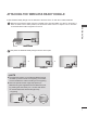
Preparation Accessories Ensure that the following accessories are included with your Wireless Media Box. If an accessory is missing, please contact the dealer where you purchased the set. ■ Image shown may differ slightly from your device. Owner’s Manual Power Cord * Lightly wipe any stains or fingerprints on the surface of the Wireless Media Box with the polishing cloth. preparation Polishing Cloth Do not use excessive force. This may cause scratching or discolouration.
preparation Front panel controls NOTE preparation ►►This product is only for home use. ►►Do not use this product in medical institutions or near medical devices. It may cause some medical devices to malfunction. ►►Wireless device used to this instrument could be set up and used only to this instrument. ►When ► using the external device connected to the Wireless Media Box, some functions of the TV menu may not work. ■ Image shown may differ slightly from your device.
BACK PANEL INFORMATION ■ Image shown may differ slightly from your device. 1 LR AV1 COM1 COM2 B HDMI2 HDMI1 RGB L(MONO) AUDIO R VIDEO LR HDMI3 3 OPTICAL DIGITAL AUDIO OUT 2 5 4 6 Component Input Connect a component video/audio device to these jacks. Audio/Video Input(AV1/2) Connect audio/video output from an external A COMPONENT / AV IN 1 device to these jacks.
preparation Wireless Ready Dongle ■ Image shown may differ slightly from your device. 2 1 preparation WIRELESS CONTROL 1 2 OUT Wireless Control Port This port is used to send and receive commands between the TV and the Wireless Media Box. HDMI Out Port This port sends the audio and video received from the Wireless Media Box to the TV. Connecting to the TV. ■ Image shown may differ slightly from your device.
Attaching the Wireless Ready Dongle ■ The Wireless Ready Dongle can be attached to the back of the TV with the included materials. 1 preparation Remove the protective paper from the included Velcro pad and attach it to the TV as shown. It does not have to be in same position, but should be close to the TV's inputs. The TV will have a recommended location engraved on the TV. Velcro 2 Now place the Wireless Ready Dongle onto the Velcro pad.
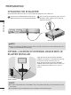
preparation Back Cover for Wire Arrangement ■ Image shown may differ slightly from your device. 1 Connection of 12 V AC/ DC Adapter ■ Image shown may differ slightly from your device. Connect the cables as necessary. (Refer to the p.6 to 7) A LR VIDEO L(MONO) AUDIO R LR B VIDEO preparation 3 DC IN 12V OPTICAL DIGITAL AUDIO OUT L(MONO) AUDIO R 2 1 2 After connecting the cables, bundle the cables and install the Cable Holder as shown.
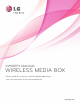
Optimal Installation Location of Wireless Media Box ■ The nearer the distance between Wireless Media Box and TV, the better the wireless function. TV X long distance X Wireless Media Box ■ We recommend that you place the Media Box and the TV in the same room. ■ The more objects that are in between the Media Box and the TV, the more the reception strength decreases. ■ If the heat from certain objects (e.g.
preparation LR VIDEO L(MONO) AUDIO R B 3 DC IN 12V OPTICAL DIGITAL AUDIO OUT SERVICE ONLY A COMPONENT / AV IN 1 B COMPONENT / AV IN 2 LR L(MONO) AUDIO VIDEO 2 R AUDIO IN 1 / DVI IN RGB IN(PC) RGB/DVI IR BLASTER A SERVICE ONLY Attaching the IR blaster ■ The IR blaster allows the LG TV to control external equipment, like a cable box.
external equipment setup ■■ To avoid damaging any equipment, never plug in any power cord until you have finished connecting all equipment. ■ Image shown may differ slightly from your device. Connecting with a Component cable Connect the video outputs (Y, PB, PR) of the external equipment (digital set-top box, DVD, etc.) to the COMPONENT IN VIDEO jacks labeled A or B on the Wireless Media Box.
external equipment setup Connecting with an HDMI cable 1 Connect the HDMI output of the external equipment (digital set-top box, DVD, etc.) to A HDMI/ VIDEO DVI IN 1, HDMI/DVI IN 2, HDMI/DVI IN 3 or HDMI IN 4 jack on the Wireless Media Box. OPTICAL DIGITAL AUDIO OUT DC IN 12V external equipment setup 2 Turn on the external equipment. 3 Select Wireless HDMI1, Wireless HDMI2, Wireless HDMI3 or Wireless HDMI4 input source using the INPUT button on the remote control of TV.
Connecting with an HDMI to DVI cable LR VIDEO L(MONO) AUDIO R B 3 DC IN 12V OPTICAL DIGITAL AUDIO OUT SERVICE ONLY 1 A COMPONENT / AV IN 1 B COMPONENT / AV IN 2 LR L(MONO) AUDIO VIDEO 2 / DVI IN R AUDIO IN 1 RGB IN(PC) RGB/DVI IR BLASTER A SERVICE ONLY 2 1 Connect the digital set-top box or the DVI output of the PC to HDMI/DVI IN 1, HDMI/DVI IN 2 or HDMI/DVI IN 3 jack on the Wireless Media Box.
external equipment setup Connecting with RCA cable LR VIDEO L(MONO) AUDIO R LR B VIDEO L(MONO) AUDIO R 3 DC IN 12V OPTICAL DIGITAL AUDIO OUT 2 SERVICE ONLY A COMPONENT / AV IN 1 B COMPONENT / AV IN 2 AUDIO IN 1 RGB IN(PC) / DVI IN RGB/DVI SERVICE ONLY external equipment setup 1 or Video Game Set Camcorder 1 VIDEO L(MONO) AUDIO 3 OPTICAL DIGITAL AUDIO OUT SERVICE ONLY L(MONO) AUDIO VIDEO R 2 / DVI IN IR BLASTER LR A COMPONENT / AV IN 1 LR Connect the AUDIO/VIDEO jacks between Wir
SERVICE ONLY AUDIO OUT RGB IN(PC) / DVI IN RGB/DVI Digital Audio Out Setup You can output the Wireless Media Box’s audio signal to external audio equipment via the Optical Digital Audio Output port. This port uses a standard optical cable. LR RGB IN(PC) RGB/DVI 1 IR BLASTER A COMPONENT / AV IN 1 B COMPONENT / AV IN 2 AUDIO IN O) AUDIO R Connect one end of an optical cable to the OPTICAL DIGITAL AUDIO OUT port on the Wireless Media Box.
external equipment setup Supported Display Resolution RGB-PC, HDMI/DVI-PC mode Resolution Horizontal Frequency(kHz) Vertical Frequency(Hz) 720x400 31.468 70.08 external equipment setup 640x480 31.469 59.94 800x600 37.879 60.31 1024x768 48.363 60.00 1280x768 47.78 59.87 1360x768 47.72 59.80 1280x1024 63.981 60.02 66.587 59.93 67.5 60.
Watching TV / Program control Turning on the Wireless Media box Firstly, connect the power cord correctly on the Wireless Media Box. At this stage, the Wireless Media Box switches to standby mode. When installing for the first time, the press the / I (Power) button of the Wireless Media Box to turn on the power.) 2 Use the remote controller of the TV to turn on the power. The power of the Wireless Media Box will automatically be turned on. Point the remote controller toward the TV.
Watching TV / Program control Input list Only input signals which are connected to a TV or Wireless Media Box can be activated and selected. ■■ Image shown may differ from your TV. Input List Move Watching TV / Programme control Antenna USB AV1 RGB HDMI1 HDMI2 OK Component1 Component2 AV2 HDMI4 HDMI3 AV1 Exit Input Label * This is the screen when the Wireless Ready Dongle is connected to HDMI/DVI IN 1.
appendix IR Code List DVD BRAND PHILIPS SAMSUNG TOSHIBA PANASONIC LG DENON PIONEER HITACHI GPX AUDIO CODE RC6 LC7461 NEC AV162 TC9012 LRC3715 NEC NEC SAA3004 DVR-VCR BRAND CODE TIVO S2 uPD6121 SAMSUNG TC9012 TOSHIBA NEC PANASONIC AV162 PHILIPS SAA3010 HITACHI NEC LG NEC MITSUBISHI JVC HITACHI M50110 GO VIDEO SAA3004 BRAND DENON YAMAHA MARANTZ CODE LRC3715 NEC SAA3010 INTEGRA, ONKYO NEC H/K PIONEER BOSE LEXICON ROTEL SHERWOOD XM REALISTIC PARASOUND INSIGNIA NEC NEC NEC uPD6121 uPD6121 uPD6121 SAA3010
appendix RF Specifications Wireless Media Box Items Frequency range [GHz] Transmission RF Output Power (Average) [dBm] Antenna Gain (Peak) [dBi] Channel Table [MHz] (Center frequency) Channel units Maximum distance (Line of sight, No interference) U-NII-I 5.15 to 5.25 OFDM 16 3.47 U-NII-II 5.25 to 5.35 OFDM 16 2.93 U-NII-II extended 5.47 to 5.725 OFDM 16 3.42 U-NII-III 5.725 to 5.825 OFDM 16 3.
Frequency Table ˕˪˯˖˛ Argentina / Brazil / Hongkong / Jordan / Peru / South Africa / Thailand ʶˆˉ ʶˇ˃ ʶˇˇ ʶˇˋ ˈˁ˄ˈʳ˚˛̍ʳ̇̂ʳˈˁ˅ˈʳ˚˛̍ ʶˈ˅ ʶˈˉ ʶˉ˃ ʶˉˇ ˈˁ˅ˈʳ˚˛̍ʳ̇̂ʳˈˁˆˈʳ˚˛̍ ˅˃ʳˠ˛̍ ͦͩ͢͡ ͦͣ͡͡ ͦͣͣ͡ ͦͣͥ͡ ͦͣͧ͡ ͦͣͩ͡ ͦͤ͡͡ ͦͤͣ͡ ͦͪ͢͡ ˇ˃ʳˠ˛̍ ͦͣͤ͡ ͦͣͨ͡ ˈˁ˄ˈʳ˚˛̍ʳ̇̂ʳˈˁ˅ˈʳ˚˛̍ CANADA / US ʶ˄ˇˌ ʶ˄ˈˆ ʶ˄ˈˊ ʶ˄ˉ˄ ʶ˄ˉˈ ˈˁˊ˅ˈʳ˚˛̍ʳ̇̂ʳˈˁˋˈ˃˚˛̍ ͦͦ͡͡ ͦͦͣ͡ ͦͦͥ͡ ͦͦͧ͡ ͦͦͩ͡ ͦͧ͡͡ ͦͧͣ͡ ͦͧͥ͡ ͦͧͧ͡ ͦͧͩ͡ ͦͨͥͦ ͦͨͧͦ ͦͨͩͦ ͦͩͦ͡ ͦͦ͢͡ ͦͤ͢͡ ͦͦͦ͡ ͦͦͪ͡ ˈˁ˅ˈʳ˚˛̍ʳ̇̂ʳˈˁˆˈʳ˚˛̍ ˅˃ʳˠ˛̍ ͦͩ͢͡ ͦͣ͡͡ ͦͣͣ͡ ͦͣͥ͡ ͦͣͧ͡ ͦͣͩ͡ ͦͤ͡͡ ͦͤͣ͡ ͦͪ͢͡ ͦͣͤ͡ ͦͣͨ͡ ͦͤ͢͡
appendix Product Specifications Wireless Media Box (AN-WL100W) MODELS Dimensions 326.0 mm x 42.8 mm x 226.0 mm (12.8 inch x 1.7 inch x 8.9 inch) (Width x Height x Depth) Weight 1.5 kg (3.3 lb) Power requirement DC 12 V 1.1 A In : AC 100-240 V~ 50 / 60 Hz Out : DC 12 V 2.5A (Adapter model No. : PA-1031-1 ( LITE-ON) , EADP-30PB B (DELTA) ) Adapter MODELS Wireless Ready Dongle Dimensions 148.0 mm x 23.0 mm x 78.0 mm (5.8 inch x 0.9 inch x 3.1 inch) (Width x Height x Depth) Weight 0.2 kg (0.
The audio function does not work. Picture OK & No sound No output from one of the speakers No sound when connecting HDMI ■■ Press the VOL +/- or ( +/-) button. ■■ Sound muted? Press MUTE button. ■■ Are the audio cables installed properly? ■■ Adjust Balance in menu option. ■■ Check HDMI cable is High Speed HDMI Cable. There is a problem in PC mode.
appendix Open Source Software Notice The following GPL executables and LGPL, MPL libraries used in this product are subject to the GPL2.0/ LGPL2.1/MPL1.1 License Agreements: GPL EXECUTABLES: Linux kernel 2.
appendix Record the model number and serial number of the TV. Refer to the label on the back cover and quote this information to your dealer when requiring any service. Model : Serial No.