6H3-9-1P Hyoshi 3/23/04 6:05 PM Page 1 60D 70D OWNER’S MANUAL Printed in Japan March 2004-–0.5 × 1 ! Printed on recycled paper U.S.A.
6H3-9-1P Hyoshi 3/23/04 6:05 PM Page 2 EMU25060 ZMU01690 Read this owner’s manual carefully before operating your outboard motor.
Important manual information EMU25100 To the owner Thank you for choosing a Yamaha outboard motor. This Owner’s Manual contains information needed for proper operation, maintenance and care. A thorough understanding of these simple instructions will help you obtain maximum enjoyment from your new Yamaha. If you have any question about the operation or maintenance of your outboard motor, please consult a Yamaha dealer.
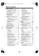
Table of contents General information .......................... 1 Identification numbers record.......... 1 Outboard motor serial number .......... 1 Key number....................................... 1 Emission control information ........... 1 North American models..................... 1 Safety information ........................... 2 Important labels............................... 3 Warning labels .................................. 3 Basic boating rules (Rules of the road) ...........................
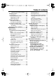
Table of contents and power trim and tilt models)..... 29 Stopping engine ............................ 30 Procedure ....................................... 30 Trimming outboard motor.............. 30 Adjusting trim angle ........................ 31 Adjusting boat trim .......................... 32 Tilting up and down ....................... 32 Procedure for tilting up .................... 33 Procedure for tilting down ............... 34 Cruising in shallow water .............. 35 Changing gear oil ....
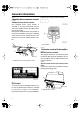
General information EMU25170 Identification numbers record reference in case you need a new key. EMU25182 Outboard motor serial number The outboard motor serial number is stamped on the label attached to the port side of the clamp bracket or the upper part of the swivel bracket. Record your outboard motor serial number in the spaces provided to assist you in ordering spare parts from your Yamaha dealer or for reference in case your outboard motor is stolen. 1.
General information ● EMISSION CONTROL INFORMATION ENGINE FAMILY : THIS ENGINE CONFORMS TO 2001 U.S. EPA REGULATIONS FOR MARINE SI ENGINES. REFER TO THE OWNERS MANUAL FOR MAINTENANCE SPECIFICATIONS AND ADJUSTMENTS. g/kw-hr FELs : IDLE SPEED : rpm IN NEUTRAL SPARK PLUG : SPARK PLUG GAP (mm) : DISPLACEMENT : cm 3 FUEL : GASOLINE ADVERTISED POWER : EX VALVE LASH (mm) : IN kw ● ZMU04304 EMU25261 Manufactured date label This label is attached to the clamp bracket or the swivel bracket.
General information er operation before starting the engine. Attach the engine stop switch lanyard cord to a secure place on your clothing, or your arm or leg while operating. If you accidentally leave the helm, the cord will pull from the switch, stopping the engine. ● Know the marine laws and regulations where you will be boating—and obey them. For basic boating rules, see “Rules of the road” on page 3. ● Stay informed about the weather. Check weather forecasts before boating.
General information cies. You should be aware of these rules, and follow them whenever you encounter another vessel on the water. Several sets of rules prevail according to geographic location, but are all basically the same as the International Rules of the Road. The rules presented here in your Owner’s Manual are condensed, and have been provided for your convenience only. Consult your local U.S.
General information Meeting If you are meeting another power vessel head on, and are close enough to run the risk of collision, neither of you has the right-ofway! Both of you should alter course to avoid an accident. You should keep the other vessel on your port (left) side. This rule doesn’t apply if both of you will clear one another if you continue on your set course and speed. Overtaking If you are passing another vessel, you are the “Give-Way” vessel.
General information or trawls are considered to be “fishing vessels” under the International Rules. Vessels with trolling lines are not considered fishing vessels. Fishing vessels have the right-ofway regardless of position. Fishing vessels cannot, however, impede the passage of other vessels in narrow channels. Sailing vessel right-of-way Sailing vessels should normally be given the right-of-way. The exceptions to this are: 1.
General information ZMU01708 EMU25540 Fueling instructions EWM00010 WARNING GASOLINE AND ITS VAPORS ARE HIGHLY FLAMMABLE AND EXPLOSIVE! ● Do not smoke when refueling, and keep 7 ● ● ● away from sparks, flames, or other sources of ignition. Stop engine before refueling. Refuel in a well-ventilated area. Refuel portable fuel tanks off the boat. Take care not to spill gasoline.
General information ● ● ● ● ● dry rags. Do not overfill the fuel tank. Tighten the filler cap securely after refueling. If you should swallow some gasoline, inhale a lot of gasoline vapor, or get gasoline in your eyes, get immediate medical attention. If any gasoline spills onto your skin, immediately wash with soap and water. Change clothing if gasoline spills on it. Touch the fuel nozzle to the filler opening or funnel to help prevent electrostatic sparks.
General information speed is too high or too low for good engine performance, this will have an adverse effect on the engine. Yamaha outboard motors are fitted with propellers chosen to perform well over a range of applications, but there may be uses where a propeller with a different pitch would be more appropriate. For a greater operating load, a smaller-pitch propeller is more suitable as it enables the correct engine speed to be maintained.
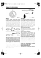
Basic components EMU25795 Main components NOTE: * May not be exactly as shown; also may not be included as standard equipment on all models. 60D, 70D 12 13 14 15 1 11 10 2 9 8 16 7 6 3 4 5 ZMU04945 1. Top cowling 2. Top cowling lock lever 3. Anti-cavitation plate 4. Trim tab (anode) 5. Propeller 6. Cooling water inlet 7. Anode 8. Trim rod 9. Clamp bracket 10. Tilt support knob 11. Power trim and tilt switch 12. Tachometer* 13. Trim meter* 14. Digital tachometer* 15.
Basic components tions. 1 3 4 2 ZMU03157 1. Fuel joint 2. Fuel gauge 3. Fuel tank cap 4. Air vent screw EMU25830 1. Power trim and tilt switch 2. Remote control lever 3. Neutral interlock trigger 4. Neutral throttle lever 5. Main switch / choke switch 6. Engine stop lanyard switch 7. Throttle friction adjuster Fuel joint EMU26190 This joint is used to connect the fuel line. Remote control lever EMU25841 Moving the lever forward from the neutral position engages forward gear.
Basic components 6. Throttle 7. Fully open EMU26201 Neutral interlock trigger To shift out of neutral, first pull the neutral interlock trigger up. 1. Fully open 2. Fully closed EMU25970 Throttle friction adjuster 1. Neutral interlock trigger EMU26211 Neutral throttle lever To open the throttle without shifting into either forward or reverse, put the remote control lever in the neutral position and lift the neutral throttle lever.
Basic components EMU25990 Engine stop lanyard switch The lock plate must be attached to the engine stop switch for the engine to run. The lanyard should be attached to a secure place on the operator’s clothing, or arm or leg. Should the operator fall overboard or leave the helm, the lanyard will pull out the lock plate, stopping ignition to the engine. This will prevent the boat from running away under power.
Basic components EMU26141 Power trim and tilt switch on remote control or tiller handle The power trim and tilt system adjusts the outboard motor angle in relation to the transom. Pressing the switch “ ” (up) trims the outboard motor up, then tilts it up. Pressing the switch “ ” (down) tilts the outboard motor down and trims it down. When the switch is released, the outboard motor will stop in its current position.
Basic components protect the engine from electrochemical corrosion. Never paint the trim tab as it will become ineffective as an anode. A ZMU02528 1 2 EMU26372 B Top cowling lock lever(s) (turn type) ZMU03097 1. Trim tab 2. Bolt EMU26261 Trim rod (tilt pin) To remove the engine top cowling, turn the lock lever(s) and lift off the cowling. When installing the cowling, check to be sure it fits properly in the rubber seal. Then lock the cowling again by returning the lever(s) to the lock position.
Basic components EMU26470 Tachometer This gauge shows the engine speed and has the following functions. 7. Engine trouble warning indicator 8. Set button 9. Mode button NOTE: 1 The water separator and engine trouble warning indicators only operate when the engine is equipped with the appropriate functions. EMU26540 2 ZMU04577 1. Tachometer 2. Oil level indicator Oil level indicators (three indicators 2) The indicators on the gauge show the status of the oil level.
Basic components rious engine damage will occur. ZMU04581 1 ZMU01867 1. Oil level indicator EMU26581 Overheat warning indicator (digital type) If the engine temperature rises too high, the warning indicator will start to blink. For further information on reading the indicator, see page 18. ECM00050 NOTE: Memorize the trim angles that work best for your boat under different conditions. Adjust the trim angle to the desired setting with the power trim and tilt switch.
Basic components engine has been run. It can be set to show the total number of hours or the number of hours for the current trip. The display can also be turned on and off. Activation of warning device ● The engine speed will automatically decrease to about 2000 r/min.
Basic components clogging. ZMU03942 ZMU03026 ● The buzzer will sound. EMU26843 Oil level warning and oil filter clogging warning Oil injection models This engine has an oil level warning system. If the oil level falls below the lower limit, the warning system will activate. Activation of warning device ● Engine speed will automatically decrease to about 2000 r/min. If the warning system has been activated, stop the engine and check for the cause.
Operation EMU26901 Installation ECM00110 CAUTION: Incorrect engine height or obstructions to smooth water flow (such as the design or condition of the boat, or accessories such as transom ladders or depth finder transducers) can create airborne water spray while the boat is cruising. Severe engine damage may result if the motor is operated continuously in the presence of airborne water spray. NOTE: During water testing check the buoyancy of the boat, at rest, with its maximum load.
Operation motor greatly affects the water resistance. If the mounting height is too high, cavitation tends to occur, thus reducing the propulsion; and if the propeller tips cut the air, the engine speed will rise abnormally and cause the engine to overheat. If the mounting height is too low, the water resistance will increase and thereby reduce engine efficiency. Mount the outboard motor so that the anti-cavitation plate is in alignment with the bottom of the boat. come loose due to engine vibration.
Operation board (if packed). For details, consult your Yamaha dealer. EWM00650 EMU27060 Gasoline and engine oil mixing chart (50:1) WARNING Avoid using bolts, nuts or washers other than those contained in the engine packaging. If used, they must be of at least the same quality of material and strength and must be tightened securely. After tightening, test run the engine and check their tightness. 1. : Gasoline 2.
Operation cool. Third through tenth hours: Avoid operating at full throttle for more than 5 minutes at a time. Let the engine cool between full-throttle runs. Vary engine speed occasionally. After the first 10 hours: Operate the engine normally. Use only straight gasoline in the fuel tank. The Yamaha oil injection system provides proper lubrication for normal operation. 4. 5.
Operation ZMU03012 ZMU03829 ECM00130 EMU27270 CAUTION: Ring Free Fuel Additive Be sure to take the above steps when operating the engine after a long period of storage. Otherwise engine seizure could occur. Gasoline is a precise blend of many different substances, each chosen to give certain characteristics. Gasoline blends have been changing in recent years in response to concerns about pollution and resulting emissions regulations.
Operation EMU27311 Filling oil for electric start models EWM00530 WARNING Do not add gasoline into the oil tank. Fire or explosion could result. This engine uses the Yamaha oil injection system, which provides superior lubrication by ensuring the proper oil ratio for all operating conditions. No fuel premixing is needed. Simply pour gasoline into the fuel tank and oil into the oil tank. Convenient indicator segments indicate the status of the oil supply.
Operation EMU27321 Oil level indicator operation The various functions of the oil level system are as follows: EMU27360 Electric start models Oil level warning indicator (analog tachometer/ bottom cowling) Oil level warning indicator (digital tachometer) Engine oil tank Green Remarks more than 770 cm3 (0.81 US qt, 0.68 Imp qt) Yellow from 770 cm3 (0.48 US qt, 0.40 Imp qt) down to No refilling necessary. Add oil; see page 25. 280 cm3 (0.30 US qt, 0.25 Imp qt) Red ● 280 cm3 (0.30 US qt, 0.
Operation from the fuel tank. 4. Squeeze the primer pump with the outlet end up until you feel it become firm. ZMU02295 2. If there is a fuel joint on the motor, firmly connect the fuel line to the joint. Then firmly connect the other end of the fuel line to the joint on the fuel tank. ZMU02025 EMU27490 Starting engine EMU27662 Electric start and remote control models 1. Place the remote control lever in neutral.
Operation ● ● to a secure place on your clothing, or your arm or leg while operating. Do not attach the lanyard to clothing that could tear loose. Do not route the lanyard where it could become entangled, preventing it from functioning. Avoid accidentally pulling the lanyard during normal operation. Loss of engine power means the loss of most steering control. Also, without engine power, the boat could slow rapidly. This could cause people and objects in the boat to be thrown forward. turn to “ ” (on).
Operation running, overheating and serious damage could occur. Stop the engine and check whether the cooling water inlet on the lower case or the cooling water pilot hole is blocked. Consult your Yamaha dealer if the problem cannot be located and corrected. equipped) and move the remote control lever quickly and firmly from neutral to forward.
Operation ZMU03834 EMU27820 Stopping engine 3. Tighten the air vent screw on the fuel tank cap (if equipped). Before stopping the engine, first let it cool off for a few minutes at idle or low speed. Stopping the engine immediately after operating at high speed is not recommended. EMU27844 Procedure 1. Push and hold the engine stop button or turn the main switch to “ ” (off). ZMU02301 4. Remove the key if the boat will be left unattended.
Operation the boat, sea conditions, and running speed. EWM00740 ● WARNING Excessive trim for the operating conditions (either trim up or trim down) can cause boat instability and can make steering the boat more difficult. This increases the possibility of an accident. If the boat begins to feel unstable or is hard to steer, slow down and/or readjust the trim angle. ● clamp bracket. Use caution when trying a trim position for the first time.
Operation your boat and operating conditions. NOTE: To adjust the trim angle while the boat is moving, use the power trim and tilt switch located on the remote control device or tiller handle, if equipped. EMU27911 Adjusting boat trim When the boat is on plane, a bow-up attitude results in less drag, greater stability and efficiency. This is generally when the keel line of the boat is up about 3 to 5 degrees. With the bow up, the boat may have a greater tendency to steer to one side or the other.
Operation salt corrosion. 2. EWM00220 Disconnect the fuel line from the outboard motor or close the fuel cock. WARNING Be sure all people are clear of the outboard motor when tilting up and down, also be careful not to pinch any body parts between the drive unit and engine bracket. EWM00250 WARNING Leaking fuel is a fire hazard. If there is a fuel joint on the outboard motor, disconnect the fuel line or close the fuel cock if the engine will be tilted for more than a few minutes.
Operation EMU28052 Procedure for tilting down ZMU02528 Power trim and tilt models / power tilt models 1. Push the power tilt / power trim and tilt switch “ ” (up) until the outboard motor is supported by the tilt rod and the tilt support lever / tilt support knob becomes free. 2. Release the tilt support lever or pull out the tilt support knob. EWM00260 WARNING After tilting the outboard motor, be sure to support it with the tilt support knob or tilt support lever.
Operation DN ZMU03838 EMU28060 2. Cruising in shallow water The outboard motor can be tilted up partially to allow operation in shallow water. Slightly tilt the outboard motor up to the desired position using the power trim / tilt switch. EMU28090 Power trim and tilt models / power tilt models The outboard motor can be tilted up partially to allow operation in shallow water. EWM00660 WARNING ● ● Place the gear shift in neutral before setting up for shallow water cruising.
Operation cooling water passages with fresh water to prevent them from becoming clogged with salt deposits. NOTE: For cooling system flushing instructions, see page 38. Cruising in turbid water Yamaha strongly recommends that you use the optional chromium-plated water pump kit if you use the outboard motor in turbid (muddy) water conditions.
Maintenance EMU28216 Specifications Dimension: Overall length: 713 mm (28.1 in) Overall width: 364 mm (14.3 in) Overall height L: 1374 mm (54.1 in) Transom height L: 521 mm (20.5 in) Weight (without propeller) L: 104.0 kg (229 lb) Performance: Full throttle operating range: 60TR 4500–5500 r/min 70TR 5000–6000 r/min Maximum output: 60TR 44.1 kW@5000 r/min (60 HP@5000 r/min) 70TR 51.5 kW@5500 r/min (70 HP@5500 r/min) Idling speed (in neutral): 800 ±50 r/min Engine: Type: 2-stroke L Displacement: 849.
Maintenance Propeller nut: 35.0 Nm (25.8 ft-lb) (3.57 kgf-m) dealer for further details. EMU28222 Transporting and storing outboard motor EWM00690 WARNING ● ● ● Leaking fuel is a fire hazard. When transporting and storing the outboard motor, close the air vent screw and fuel cock to prevent fuel from leaking. USE CARE when transporting fuel tank, whether in a boat or car. DO NOT fill fuel container to maximum capacity.
Maintenance lowing procedures. es. ECM01411 CAUTION: ● ● Do not place the outboard motor on its side before the cooling water has drained from it completely, otherwise water may enter the cylinder through the exhaust port and cause engine trouble. Store the outboard motor in a dry, wellventilated place, not in direct sunlight. ECM00310 CAUTION: Avoid running the outboard motor at high speed while on the flushing attachment, otherwise overheating could occur.
Maintenance 8. 9. done, the engine will smoke excessively and almost stall. Remove the flushing attachment and wipe off any excess water. Install the silencer cover/cap and top cowling. Install the propeller. NOTE: A flushing attachment is available from your Yamaha dealer. EMU28410 Lubrication (oil injection models) 1. 2. 3. 4. Grease the spark plug threads and install the spark plug(s) and torque to proper specification. For information on spark plug installation, see page 44. Fill the oil tanks.
Maintenance 1. 2. 3. 4. Disconnect and remove the battery from the boat. Always disconnect the black negative cable first to prevent the risk of shorting. Clean the battery casing and terminals. Fill each cell to the upper level with distilled water. Store the battery on a level surface in a cool, dry, well-ventilated place out of direct sunlight. Once a month, check the specific gravity of the electrolyte and recharge as required to prolong battery life.
Maintenance EMU28521 Maintenance chart Frequency of maintenance operations may be adjusted according to the operating conditions, but the following table gives general guidelines. Refer to the sections in this chapter for explanations of each owner-specific action. The “ ” symbol indicates the check-ups which you may carry out yourself. The “ ” symbol indicates work to be carried out by your Yamaha dealer.
Maintenance Initial Item Actions Oil tank water drain Inspection / cleaning Spark plug(s) Cleaning / adjustment / replacement 10 hours (1 month) 50 hours (3 months) Every 100 hours (6 months) 200 hours (1 year) NOTE: When operating in salt water, turbid or muddy water, the engine should be flushed with clean water after each use.
Maintenance EMU28951 Cleaning and adjusting spark plug EWM00560 WARNING When removing or installing a spark plug, be careful not to damage the insulator. A damaged insulator could allow external sparks, which could lead to explosion or fire. The spark plug is an important engine component and is easy to inspect. The condition of the spark plug can indicate something about the condition of the engine.
Maintenance sources of ignition. EMU28980 Inspecting fuel filter EWM00910 EWM00310 WARNING WARNING Leaking fuel can result in fire or explosion. ● Check for fuel leakage regularly. ● If any fuel leakage is found, the fuel system must be repaired by a qualified mechanic. Improper repairs can make the outboard unsafe to operate. Check the fuel lines for leaks, crack, or malfunction. If a problem is found, your Yamaha dealer or other qualified mechanic should repair it immediately.
Maintenance 3. spilled fuel in a rag. Remove the filter element, and wash it in solvent. Allow it to dry. Inspect the filter element and O-ring to make sure they are in good condition. Replace them if necessary. If any water is found in the fuel, the Yamaha portable fuel tank or other fuel tanks should be checked and cleaned. 3 4 1 ZMU02079 1. Filter cup 2. Filter element 3. Filter housing 4. O-ring 5. 6. Reinstall the filter element in the cup. Make sure the O-ring is in position in the cup.
Maintenance neck. If water or foreign matter collects in this hose, consult a Yamaha dealer. EMU29153 Checking power trim and tilt system EWM00430 WARNING 2 ● ● 1 ZMU03898 1. 2. 1. Drain hose 2. Filler neck side EMU29111 Checking wiring and connectors ● ● Check that each grounding wire is properly secured. Check that each connector is engaged securely. ZMU03841 3. Never get under the lower unit while it is tilted, even when the tilt support lever is locked.
Maintenance 1. Tilt support lever 5. 6. 7. Check that the tilt rod and trim rods are free of corrosion or other flaws. Activate the tilt-down switch until the trim rods have retracted completely into the cylinders. Activate the trim-up switch until the tilt rod is fully extended. Unlock the tilt support lever. gine accidentally starts when you are near the propeller. ● Before inspecting, removing, or installing the propeller, remove the spark plug caps from the spark plugs.
Maintenance ● ● ● tion, or other damage. Check the propeller shaft for damage. Check the splines / shear pin for wear or damage. Check for fish line tangled around the propeller shaft. 1. Cotter pin 2. Propeller nut 3. Washer 4. Spacer 5. Propeller 6. Thrust washer ● Check the propeller shaft oil seal for damage. 1 3 NOTE: If the shear pin equipped: it is designed to break if the propeller hits a hard underwater obstacle to help protect the propeller and drive mechanism.
Maintenance ● 1. 2. 3. 4. the lower case and propeller boss could be damaged. Be sure to use a new cotter pin and bend the ends over securely. Otherwise the propeller could come off during operation and be lost. Apply Yamaha marine grease or a corrosion resistant grease to the propeller shaft. Install the spacer(if equipped), thrust washer, and propeller on the propeller shaft. Install the spacer (if equipped) and the washer. Tighten the propeller nut to the specified torque.
Maintenance NOTE: For disposal of used oil consult your Yamaha dealer. 5. With the outboard motor in a vertical position, and using a flexible or pressurized filling device, inject the gear oil into the gear oil drain screw hole. Recommended gear oil: Hypoid gear oil SAE#90 Gear oil quantity: 610.0 cm3 (20.62 US oz) (21.51 Imp.oz) ● ● ● ● 1. 2. 3. when cleaning the fuel tank. Remove the fuel tank from the boat before cleaning it. Work only outdoors in an area with good ventilation.
Maintenance Yamaha dealer for replacement of external anodes. ECM00720 CAUTION: Do not paint anodes, as this would render them ineffective. NOTE: Inspect ground leads attached to external anodes on equipped models. Consult a Yamaha dealer for inspection and replacement of internal anodes attached to the power unit. ZMU01901 poisonous and highly caustic. Always follow these preventive measures: ● Avoid bodily contact with electrolytic fluid as it can cause severe burns or permanent eye injury.
Maintenance up only with distilled water (or pure deionized water suitable to use in batteries). ● ● ● 2. Always keep the battery in a good state of charge. Installing a voltmeter will help you monitor your battery. If you will not use the boat for a month or more, remove the battery from the boat and store it in a cool, dark place. Completely recharge the battery before using it.
Maintenance ZMU04678 EMU29400 Coating the boat bottom A clean hull improves boat performance. The boat bottom should be kept as clean of marine growth as possible. If necessary, the boat bottom can be coated with an anti-fouling paint approved for your area to inhibit marine growth. Do not use anti-fouling paint which includes copper or graphite. These paints can cause more rapid engine corrosion.
Trouble Recovery EMU29422 Troubleshooting A problem in the fuel, compression, or ignition systems can cause poor starting, loss of power, or other problems. This section describes basic checks and possible remedies, and covers all Yamaha outboard motors. Therefore some items may not apply to your model. If your outboard motor requires repair, bring it to your Yamaha dealer. If the engine trouble warning indicator is flashing, consult your Yamaha dealer. Starter will not operate. Q.
Trouble Recovery Q. Is fuel system obstructed? A. Check for pinched or kinked fuel line or other obstructions in fuel system. Q. Is fuel contaminated or stale? A. Fill tank with clean, fresh fuel. Q. Is fuel filter clogged? A. Clean or replace filter. Q. Have ignition parts failed? A. Have serviced by a Yamaha dealer. Q. Has warning system activated? A. Find and correct cause of warning. Q. Is spark plug gap incorrect? A. Inspect and adjust as specified. Q. Is ignition wiring damaged or poorly connected? A.
Trouble Recovery A. Have serviced by a Yamaha dealer. Q. Is load on boat improperly distributed? A. Distribute load to place boat on an even plane. Q. Are weeds or other foreign matter tangled on gear housing? A. Remove foreign matter and clean lower unit. Q. Is water pump or thermostat faulty? A. Have serviced by a Yamaha dealer. Q. Is fuel system obstructed? A. Check for pinched or kinked fuel line or other obstructions in fuel system. Q. Is there excess water in fuel filter cup? A. Drain filter cup.
Trouble Recovery board motor unsafe to operate. Q. Is heat range of spark plug incorrect? A. Inspect spark plug and replace it with recommended type. If the outboard motor hits an object in the water, follow the procedure below. Q. Is high pressure fuel pump drive belt broken? A. Have serviced by a Yamaha dealer. Q. Is engine not responding properly to shift lever position? A. Have serviced by a Yamaha dealer. Engine vibrates excessively. Q. Is propeller damaged? A. Have propeller repaired or replaced.
Trouble Recovery EMU29531 Starter will not operate 1 If the starter mechanism does not operate (the engine cannot be cranked with the starter), the engine can be started with an emergency starter rope. EWM01020 WARNING 2 ● ZMU02561 ● 1. Fuse holder 2. Fuse (20 A) NOTE: Consult your Yamaha dealer if the new fuse immediately blows again.
Trouble Recovery ● starter mechanism or top cowling after the engine is running. Do not touch the ignition coil, spark plug wire, spark plug cap, or other electrical components when starting or operating the motor. You could get an electrical shock. ON OFF EMU29573 Emergency starting engine 1. 2. 3. ZMU03541 Remove the top cowling. Disconnect the start-in-gear protection cable from the starter, if equipped. Remove the starter/flywheel cover after removing the bolt(s). 5. 6. 7.
Trouble Recovery procedure below. 1. Remove the CDI unit cover or electrical cover, if equipped. 2. Disconnect the yellow cord (emergency circuit) of the CDI unit to return to port. flywheel or other moving parts when the engine is running. 1. EWM00350 2. WARNING When the yellow cord is disconnected, the idle and low speeds are slightly higher than normal. Use care when starting off or stopping. Adjust the trim angle so that the drive shaft is at right angles to the water surface or is trimmed in.
Trouble Recovery ON N ZMU03845 5. Turn the main switch to “ ” (on). START ZMU03922 7. ON After the engine starts, close the emergency starter valve (if used), then return the throttle to its original position. OFF OPEN CLOSE ZMU03541 6. Turn the main switch to “ ” (start). ZMU03145 ECM00191 CAUTION: ● ● Never turn the main switch to “ ” (start) while the engine is running. Do not keep the starter motor turning for more than 5 seconds.
Trouble Recovery dealer as soon as possible. ECM00400 CAUTION: Do not attempt to run the outboard motor until it has been completely inspected. ZMU01909 2. Remove the spark plugs and face the spark plug holes downward to allow any water, mud, or contaminants to drain. ZMU01910 3. 4. Drain the fuel from the carburetor, fuel filter, and fuel line. Feed fogging oil or engine oil through the carburetor(s) and spark plug holes while cranking with the manual starter or emergency starter rope. ZMU01911 5.
Consumer information EMU29811 Important warranty information for U.S.A.
Consumer information 65
Consumer information EMU29820 YAMAHA MOTOR CORPORATION, U.S.A.
Consumer information 67
Consumer information 68
Consumer information EMU29840 IMPORTANT WARRANTY INFORMATION IF YOU USE YOUR YAMAHA OUTSIDE U.S.A.
6H3-9-1P Hyoshi 3/23/04 6:05 PM Page 1 60D 70D OWNER’S MANUAL Printed in Japan March 2004-–0.5 × 1 ! Printed on recycled paper U.S.A.
Warranty card 2/27/02 11:47 AM Page 1 OUTBOARD MOTOR WARRANTY REGISTRATION ENREGISTREMENT DE LA GARANTIE DU MOTEUR HORS-BORD Please complete and mail this card. This information is necessary to accurately register your unit for warranty. Veuillez signer ci-dessous pour attester que le montage et l’inspection ont été faits dans le respect des directives d’inspection et que la marche à suivre pour la garantie et l’entretien a été expliquée à l’acheteur au détail.
Warranty card 2/27/02 11:47 AM Page 2 PLACE POSTAGE HERE ATTN: WARRANTY DEPARTMENT