
Service manual


RX-V363/HTR-6130
15
RX-V363/HTR-6130
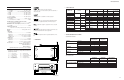
3. Removal of HDMI P.C.B.
a. Remove CB904 and CB905. (Fig. 2)
b. Remove 5 screws (5). (Fig. 3)
c. Remove HDMI P.C.B.. (Fig. 2)
4. Removal of OPERATION (4) P.C.B.
a. Remove CB193 and CB182. (Fig. 2)
b. Remove 7 screws (6). (Fig. 3)
c. Remove OPERATION (4) P.C.B.. (Fig. 2)
5. Removal of DSP P.C.B.
a. Remove 18 screws (7), 3 screws (8) and 2 screws (9) (R, L models). (Fig. 3)
b. Remove cord stopper. (Fig. 2)
c. Remove rear panel. (Fig. 2)
d. Remove screw (0). (Fig. 2)
e. Remove CB512 and CB516. (Fig. 2)
f. Remove the DSP P.C.B. which is connected directly to the MAIN (1) P.C.B. with board-to-board connectors. (Fig. 2)
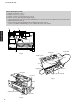
Fig. 2
Fig. 3
Rear panel
Cord stopper
CB193
CB516
CB512
CB182
CB502
CB501
CB164
CB101
MAIN (1) P.C.B.
DSP P.C.B.
OPERATION (4) P.C.B.HDMI P.C.B.
DSP P.C.B.
• Board-to-board connectors
CB181
CB905CB904
0
6 5
98
(R, L models)
7