BLACK DIC 2181s* UCAB Stereo Amplifier Amplificateur Stéréo OWNER’S MANUAL MODE D’EMPLOI
HiFi Began with Yamaha Yamaha’s involvement with and passion for music goes back more than a century, to when we built our first reed organ in 1887. Now we are the world’s leading producer of pianos and other musical instruments, and are involved with music in many other ways as well. We manufacture professional recording equipment, we design concert halls and we assist artists at concerts with set up and sound tuning. This knowledge and experience benefits our production of audio components in many ways.
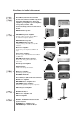
Excellence in Audio Achievement First HiFi System introduced in 1920 We introduced numerous HiFi components (turntables, FM/AM tuners, integrated amplifiers, preamplifiers, power amplifiers and speakers) in 1955 - 1965. Natural Sound Speaker Series introduced in 1967 NS-20 Monitor Speaker CA-1000 Integrated Amplifier Featuring A-Class operation, the CA-1000 set the standard for integrated amplifiers.
◆ Full floating and balanced circuit design achieves for the first time the full potential of analogue amplification An entirely new floating and balanced power amp achieves complete symmetry and permits full balanced transmission (amplification) from the input jack to just before the speaker jack ◆ Full-stage balanced signal transmission The world’s first integrated amp to offer full stage balanced transmission, combining high power output with good sound texture and outstanding S/N performance ◆ Floatin
Controls and functions In this chapter, you will learn the controls and functions of A-S2000.
Controls and functions ■ Front panel (left side) BASS - POWER PHONES TRIM ON -6 0 SPEAKERS +6 OFF A B A+B BI-WIRING +12 dB OFF 1 + 2 3 1 POWER Press upward or downward to turn on or off this unit. y The POWER indicator above lights up when this unit is turned on. 4 5 2 Remote control sensor Receives signals from the remote control. The remote control transmits a directional infrared beam.
INPUT TREBLE BALANCE VOLUME CD BAL LINE 1 CD LINE 2 MAIN DIRECT - + L TUNER PHONO R PHONO MM AUDIO MUTE MC 3 PHONES jack Outputs audio for private listening with headphones. Note When headphones are plugged in: – Both speaker sets connected to the SPEAKERS L/R CH A and B terminals are turned off. – No signals are output at the PRE OUT jacks, while signals are output at the REC jacks. – You cannot select MAIN DIRECT as the input source.
Controls and functions ■ Front panel (right side) BASS - POWER PHONES ON TRIM -6 0 SPEAKERS +6 OFF +12 OFF + A B A+B BI-WIRING dB 6 6 BASS Increases or decreases the low frequency response. The 0 position produces a flat response. Control range: –10 dB to +10 dB 7 TREBLE Increases or decreases the high frequency response. The 0 position produces a flat response.
INPUT TREBLE BALANCE VOLUME CD BAL CD LINE 1 TUNER LINE 2 MAIN DIRECT - + L PHONO R PHONO MM AUDIO MUTE MC 7 8 9 0 0 INPUT selector Selects the input source you want to listen to. The audio signals of the selected input source are also output at the REC jacks. Notes • Switch to the CD BAL position to select the CD player connected to the CD BAL jacks (balanced XLR jacks). • Switch to the CD position to select the CD player connected to the CD jacks (unbalanced RCA jacks).
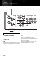
Controls and functions ■ Rear panel 1 2 3 SPEAKERS R CH INPUT LINE2 A CD BAL TUNER LINE 1 PB REC L L R CD R B R L GND PHONO See page 14 for connection information. 1 SPEAKERS L/R CH terminals 2 INPUT jacks 3 LINE2 jacks 4 MAIN IN jacks Note Adjust the volume level using the volume control on the external amplifier connected to the MAIN DIRECT jacks when you select MAIN DIRECT as the input source.
4 5 1 6 SPEAKERS L CH MAIN IN PRE OUT 7 VOLTAGE SELECTOR A 230240V L R AC IN B 8 6 AC IN Use this inlet to plug in the supplied power cable. 7 VOLTAGE SELECTOR (Asia and General models only) The VOLTAGE SELECTOR on the rear panel of this unit must be set for your local main voltage BEFORE plugging the AC power cable into the AC wall outlet. Improper setting of the VOLTAGE SELECTOR may cause damage to this unit and create a potential fire hazard.
Controls and functions ■ Remote control 4 Amplifier control buttons 1 INPUT / Selects the input source you want to listen to. A/B/C/D/E Notes • When MAIN DIRECT is selected as the input source, no signals are output at the PRE OUT and REC jacks. • If headphones are plugged into the PHONES jack while MAIN DIRECT is selected as the input source, no audio is output at the PHONES jack. 2 PRESET VOL +/– Controls the volume level.
Connections In this section, you will make connections between A-S2000, speakers, and source components.
Connections Speakers A (R channel) CD player with RCA jacks CD player with XLR jacks Tuner + - SPEAKERS R CH A LINE2 INPUT CD BAL TUNER LINE 1 PB MAIN IN REC PRE OUT L L R CD R B R L GND PHONO + Ground Speakers B (R channel) Turntable DVD player, etc. Caution • Do not let the bare speaker wires touch each other or do not let them touch any metal part of this unit. This could damage this unit and/or the speakers.
External amplifier or active subwoofer Preamplifier, AV receiver, etc. Speakers A (L channel) - SPEAKERS L CH LINE2 INPUT TUNER LINE 1 PB + MAIN IN REC PRE OUT A L L R AC IN B L GND – + Speakers B (L channel) CD recorder, tape deck, etc. Caution Fig. 1 Fig. 2 + + L L – – – English – R R + + • Because the power amplifier of A-S2000 is of the floating balanced type, the following types of connections are not possible.
Connections ■ Connecting the speakers ■ Connecting the banana plug (Except for Europe models) 1 Remove approximately 10 mm (0.4 in) of insulation from the end of each speaker cable and twist the exposed wires of the cable together to prevent short circuits. First, tighten the knob and then insert the banana plug into the end of the corresponding terminal. 10 mm (0.4 in) Banana plug 2 Unscrew the knob and then insert the bare wire into the hole.
■ Bi-wire connection ■ Connecting to the CD BAL jacks The bi-wire connection separates the woofer from the combined midrange and tweeter section. A bi-wire compatible speaker has four binding post terminals. These two sets of terminals allow the speaker to be split into two independent sections. This split connects the mid and high frequency drivers to one set of terminals and the low frequency driver to the other pair. Connect your CD player with the XLR balanced output jacks.
Connections ■ VOLTAGE SELECTOR (Asia and General models only) Caution The VOLTAGE SELECTOR on the rear panel of this unit must be set for your local voltage BEFORE plugging the power cable into the AC wall outlet. Improper setting of the VOLTAGE SELECTOR may cause damage to this unit and create a potential fire hazard. Rotate the VOLTAGE SELECTOR clockwise or counterclockwise to the correct position using a straight slot screwdriver. Voltages are as follows: ........................
Specifications In this section, you will find technical specifications for A-S2000.
Specifications POWER SECTION CONTROL SECTION • Minimum RMS Output Power (8 Ω , 20 Hz to 20 kHz, 0.02% THD) ...................... 90 W + 90 W (4 Ω , 20 Hz to 20 kHz, 0.02% THD) .................. 150 W + 150 W • Input Sensitivity/Input Impedance CD, etc. .................................................................. 150 mV/47 kΩ MM ......................................................................... 2.5 mV/47 kΩ MC ...........................................................................
■ Block diagram CD BAL PHONO CD HOT (POSITIVE PHASE) COLD (NEGATIVE PHASE) EQ AMP MC HEAD AMP MM/MC BUFFER AMP INPUT SELECTOR HOT COLD for LINE AMP2 for VOLUME1 TONE CONTROL DEVICES FLAT TONE CONTROL DEVICES FLAT TONE CONTROL/FLAT SUB TRANSFORMER (for POWER AMP / VOLTAGE AMP STAGE) POWER SWITCH HOT COLD BALANCE ⇐⇒ UNBALANCE CONVERTER MAIN TRANSFORMER MAIN DIRECT FLOATING BALANCE POWER AMPLIFIER SPEAKER DRIVER HOT (POSITIVE PHASE) SIDE for COLD R CH for HOT R CH for COLD L C
Specifications ■ Tone control characteristics +15 +12.5 +10 Response (dB) +7.5 +5 +2.5 0 –2.5 –5 –7.5 –10 –12.5 –15 10 20 50 100 200 500 1k 2k 5k 10k 20k 50k 100k Frequency (Hz) ■ Total harmonic distortion 1 0.5 THD + N Ratio (%) 0.2 0.1 0.05 0.02 20kHz 0.01 20Hz 0.005 1kHz 0.002 0.
■ Total harmonic distortion (PHONO) 10 5 THD + N Ratio (%) 2 1 0.5 0.2 0.1 0.05 20Hz 1kHz 20kHz 0.02 0.01 0.005 0.002 0.001 0.0005 0.0002 0.
Troubleshooting Refer to the chart below if this unit does not function properly. If the problem you are experiencing is not listed below or if the instructions below do not help, turn off this unit, disconnect the AC power cable, and contact the nearest authorized Yamaha dealer or service center. Problem Cause Remedy See page The AC power cable is not connected to the AC IN inlet on the rear panel or not plugged in the AC wall outlet. Connect the AC power cable firmly.
Problem Cause Remedy See page — The volume level is low while playing a record. Incorrect setting for the PHONO switch on the front panel. Switch the PHONO switch to the MM or MC position according to the type of magnetic cartridge of the turntable. The sound is degraded when listening with the headphones connected to the CD player connected to this unit. The power of this unit is turned off. Turn on the power of this unit. The remote control does not work or function properly.
BLACK DIC 2181s* © 2007 All rights reserved. YAMAHA ELECTRONICS CORPORATION, USA 6660 ORANGETHORPE AVE., BUENA PARK, CALIF. 90620, U.S.A. YAMAHA CANADA MUSIC LTD. 135 MILNER AVE., SCARBOROUGH, ONTARIO M1S 3R1, CANADA YAMAHA ELECTRONIK EUROPA G.m.b.H. SIEMENSSTR. 22-34, 25462 RELLINGEN BEI HAMBURG, GERMANY YAMAHA ELECTRONIQUE FRANCE S.A. RUE AMBROISE CROIZAT BP70 CROISSY-BEAUBOURG 77312 MARNE-LA-VALLEE CEDEX02, FRANCE YAMAHA ELECTRONICS (UK) LTD.
UCAB Stereo amplifier Amplificateur Stéréo SAFETY BROCHURE BROCHURE SUR LA SECURITE
IMPORTANT SAFETY INSTRUCTIONS CAUTION RISK OF ELECTRIC SHOCK DO NOT OPEN CAUTION: TO REDUCE THE RISK OF ELECTRIC SHOCK, DO NOT REMOVE COVER (OR BACK). NO USER-SERVICEABLE PARTS INSIDE. REFER SERVICING TO QUALIFIED SERVICE PERSONNEL.
1 IMPORTANT NOTICE: DO NOT MODIFY THIS UNIT! This product, when installed as indicated in the instructions contained in this manual, meets FCC requirements. Modifications not expressly approved by Yamaha may void your authority, granted by the FCC, to use the product. 2 IMPORTANT: When connecting this product to accessories and/or another product use only high quality shielded cables. Cable/s supplied with this product MUST be used. Follow all installation instructions.
Caution: Read this before operating your unit. 1 To assure the finest performance, please read this manual carefully. Keep it in a safe place for future reference. 2 Install this sound system in a well ventilated, cool, dry, clean place – away from direct sunlight, heat sources, vibration, dust, moisture, and/or cold. Allow ventilation space of at least 30 cm on the top, 20 cm on the left and right, and 20 cm on the back of this unit.
■ Handling the remote control • Change all of the batteries if you notice that the operation range of the remote control decreases. • Use AA, R6, UM-3 batteries. • Make sure that the polarities are correct. See the illustration inside the battery compartment. • Remove the batteries if the remote control is not used for an extended period of time. • Do not use old batteries together with new ones. • Do not use different types of batteries (such as alkaline and manganese batteries) together.
© 2007 YAMAHA ELECTRONICS CORPORATION, USA 6660 ORANGETHORPE AVE., BUENA PARK, CALIF. 90620, U.S.A. YAMAHA CANADA MUSIC LTD. 135 MILNER AVE., SCARBOROUGH, ONTARIO M1S 3R1, CANADA YAMAHA ELECTRONIK EUROPA G.m.b.H. SIEMENSSTR. 22-34, 25462 RELLINGEN BEI HAMBURG, GERMANY YAMAHA ELECTRONIQUE FRANCE S.A. RUE AMBROISE CROIZAT BP70 CROISSY-BEAUBOURG 77312 MARNE-LA-VALLEE CEDEX02, FRANCE YAMAHA ELECTRONICS (UK) LTD. YAMAHA HOUSE, 200 RICKMANSWORTH ROAD WATFORD, HERTS WD18 7GQ, ENGLAND YAMAHA SCANDINAVIA A.B.
A-S2000_CD-S2000_Flyer.fm Page 1 Friday, September 21, 2007 4:20 PM A-S2000/CD-S2000 Note on transport tape English Upon shipment from the factory, magnet feet are fixed with transport tape to this unit’s feet. Remove the transport tape before placing this unit. Remarque sur le ruban adhésif Deutsch Bei Versand ab Werk sind die Magnetfüße mit Transportband an den Füßen des Geräts befestigt. Entfernen Sie das Transportband vor der Aufstellung des Geräts.