UC Integrated Amplifier Amplificateur Intégré OWNER’S MANUAL MODE D’EMPLOI
IMPORTANT SAFETY INSTRUCTIONS CAUTION RISK OF ELECTRIC SHOCK DO NOT OPEN CAUTION: TO REDUCE THE RISK OF ELECTRIC SHOCK, DO NOT REMOVE COVER (OR BACK). NO USER-SERVICEABLE PARTS INSIDE. REFER SERVICING TO QUALIFIED SERVICE PERSONNEL.
IMPORTANT SAFETY INSTRUCTIONS FCC INFORMATION (for US customers) 1 IMPORTANT NOTICE: DO NOT MODIFY THIS UNIT! This product, when installed as indicated in the instructions contained in this manual, meets FCC requirements. Modifications not expressly approved by Yamaha may void your authority, granted by the FCC, to use the product. 2 IMPORTANT: When connecting this product to accessories and/or another product use only high quality shielded cables. Cable/s supplied with this product MUST be used.
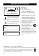
CAUTION: READ THIS BEFORE OPERATING YOUR UNIT. 1 2 3 4 5 6 7 8 9 10 11 12 13 14 15 16 To assure the finest performance, please read this manual carefully. Keep it in a safe place for future reference. Install this sound system in a well ventilated, cool, dry, clean place - away from direct sunlight, heat sources, vibration, dust, moisture, and/or cold. For proper ventilation, allow the following minimum clearances around this unit.
CONTENTS OPERATION USEFUL FEATURES ............................................ 1 SUPPLIED ACCESSORIES ................................. 1 CONTROLS AND FUNCTIONS ......................... 2 Front panel and Remote control ................................ 2 About the remote control ........................................... 3 Rear panel .................................................................. 4 PLAYING AND RECORDING.............................8 Playing a source...................................
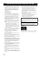
CONTROLS AND FUNCTIONS Front panel and Remote control (A-S500) 1 A (POWER) Front panel: A switch Turns on and off the power of this unit. On position: Pushed inward Off position: Released outward Remote control: A button When this unit is turned on: turns this unit on or sets it to standby mode. Note This unit consumes a small amount of power even when turned off or when in standby mode.
CONTROLS AND FUNCTIONS D VOLUME control VOLUME +/– Control the sound output level. This does not affect the REC level for recording. 7 SPEAKERS selector Turn on or off the speaker set connected to the SPEAKERS A and/or B terminals on the rear panel each time the corresponding SPEAKERS selector is set to A, B or A+B. MUTE button (Remote control only) Decreases the current volume by about 20 dB.
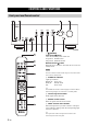
CONTROLS AND FUNCTIONS Rear panel 1 CD input jacks Used to connect a CD player (see page 5). 2 PHONO jacks and GND terminal Used to connect a turntable that uses an MM cartridge, and to ground the terminal (see page 5). 3 Audio input/output jacks Used to connect external components, such as a tuner, etc (see page 5). 4 DOCK jack Used to connect an optional Yamaha Universal Dock for iPod or Wireless System for iPod (see page 10).
PREPARATION CONNECTIONS Connecting speakers and source components CAUTION Turntable Speakers A DVD player, etc. Audio out Audio out CD player GND Audio out Audio out Tuner CD recorder, etc. Audio out Audio in PREPARATION • Do not connect this unit or other components to the main power until all connections between components are complete. • All connections must be correct: L (left) to L, R (right) to R, “+” to “+” and “–” to “–”.
CONNECTIONS CAUTION • The IMPEDANCE SELECTOR switch must be set to the appropriate position before connecting speaker sets. See page 4 for details. • Do not let the bare speaker wires touch each other or any metal part of this unit. This could damage this unit and/or the speakers. • Do not connect this unit or other components to the main power until all connections between components are complete.
CONNECTIONS Connecting the power cable POWER MANAGEMENT To the wall outlet with the power cable PREPARATION ■ POWER MANAGEMENT switch Enables or disables the automatic power down function. When the automatic power down function is enabled, this unit will automatically switch to standby mode if no operations are performed for 8 hours. ■ Connecting the power cable Plug the power cable into the wall outlet after all other connections are complete.
OPERATION PLAYING AND RECORDING Playing a source SPEAKERS VOLUME 5 Play the selected input source. 6 Rotate the VOLUME control on the front panel (or press VOLUME +/– buttons on the remote control) to adjust the sound output level. y You can adjust the tonal quality by using the BASS, TREBLE, BALANCE and LOUDNESS controls, or the PURE DIRECT switch on the front panel. A INPUT INPUT 7 When finished listening, press A switch on the front panel outward to turn off this unit.
PLAYING AND RECORDING ■ Adjusting the BASS and TREBLE controls The BASS and TREBLE controls adjust high and low frequency response. The center position produces a flat response. BASS When you feel there is not enough bass (low frequency sound), rotate clockwise to boost. When you feel there is too much bass, rotate counterclockwise to suppress. Control range: –10 dB to +10 dB (20 Hz) TREBLE When you feel there is not enough treble (high frequency sound), rotate clockwise to boost.
PLAYING BACK TUNES FROM YOUR iPhone/iPod Once you have connected an optional Yamaha Universal Dock for iPod or Wireless System for iPod to the DOCK jack on the rear panel of this unit, you can enjoy playback of your iPhone/iPod using the remote control supplied with this unit. Position the connected device as far as possible from the unit.
PLAYING BACK TUNES FROM YOUR iPhone/iPod Using a Universal Dock for iPod After setting your iPhone/iPod in your dock, rotate the INPUT selector on the front panel (or press DOCK button on the remote control) to select DOCK as the input source to play your iPhone/iPod. or Front panel Note Some shuffle modes and repeat modes may not be available depending on the model or the software version of your iPhone/ iPod.
PLAYING BACK TUNES FROM YOUR iPhone/iPod Using a Wireless System for iPod YID-W10 receiver YID-W10 transmitter ■ Establishing a wireless connection Once the iPhone/iPod is connected to the transmitter and playback begins, it takes about 5 seconds for audio to be heard. During this time the wireless connection between the transmitter and receiver is established. The status of the wireless connection between the transmitter and receiver is indicated by the respective status indicator.
ADDITIONAL INFORMATION TROUBLESHOOTING Refer to the chart below if this unit does not function properly. If the problem you are experiencing is not listed below or if the instructions below do not help, turn off this unit, disconnect the power cable, and contact the nearest authorized Yamaha dealer or service center. ■ General Problems This unit is not turned on. The POWER on indicator also does not light up. This unit turns off suddenly and the POWER on indicator blinks.
TROUBLESHOOTING Problems No sound. Possible Causes Solutions Refer to page Sound is muted. Press MUTE button on the remote control or rotate the VOLUME control. 3 Incorrect cable connections. Connect the stereo cable for audio units and the speaker wires properly. If the problem persists, the cables may be defective. 5 Playback has been stopped on the connected component. Turn the component on and start playback. No appropriate input source has been selected.
TROUBLESHOOTING Problems Using the BASS, TREBLE, BALANCE and LOUDNESS controls does not affect the tonal quality. Possible Causes The PURE DIRECT switch is turned on. Solutions Refer to page The PURE DIRECT switch must be turned off to use those controls. 8 ■ Universal Dock for iPod and Wireless System for iPod Problems No sound. You cannot operate the iPhone/iPod. When using a Wireless System for iPod: Sound frequently cuts out.
TROUBLESHOOTING ■ Remote control Solutions Refer to page The remote control is too far away or tilted too much. The remote control will function within a maximum range of 6 m (20 ft) and no more than 30 degrees offaxis from the front panel. 3 Direct sunlight or lighting (from an inverter type of fluorescent lamp, etc.) is striking the remote control sensor of this unit. Reposition this unit or lighting. The batteries are weak. Replace all batteries.
SPECIFICATIONS AUDIO SECTION • Minimum RMS output power (8 Ω, 20 Hz to 20 kHz, 0.019% THD) [A-S500] ................................................................ 85 W + 85 W [A-S300] ................................................................ 60 W + 60 W (6 Ω, 20 Hz to 20 kHz, 0.038% THD) [Except for Asia model] [A-S500] ............................................................ 100 W + 100 W [A-S300] ................................................................
Printed in Malaysia ZE28070