L Integrated Amplifier OWNER’S MANUAL MANUAL DE INSTRUCCIONES © 2013 Yamaha Corporation Printed in Malaysia ZK04740-1
A Living Tradition in Sound A piano comes into this world through the perfect synergy of advanced technical skill and artistry. Such a piano can create sound that truly reflects the player’s feelings. The final stage in piano production is called “voicing”. It is here that the instrument is given its soul.
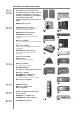
Excellence in Audio Achievement First HiFi System introduced in 1920 We introduced numerous HiFi components (turntables, FM/AM tuners, integrated amplifiers, preamplifiers, power amplifiers and speakers) in 1955 - 1965. Natural Sound Speaker Series introduced in 1967 NS-20 Monitor Speaker CA-1000 Integrated Amplifier Featuring A-Class operation, the CA-1000 set the standard for integrated amplifiers.
◆ Full floating and balanced circuit design achieves the full potential of analogue amplification An entirely new floating and balanced power amplifier achieves complete symmetry and permits full balanced transmission (amplification) from the input jack to just before the speaker jack. ◆ Full-stage balanced signal transmission The integrated amplifier offers full stage balanced transmission, combining high power output with good sound texture and outstanding S/N performance.
Controls and functions In this chapter, you will learn the controls and functions of A-S3000.
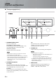
Controls and functions ■ Front panel (pages 6 to 9) LEFT – 60 40 30 0.01 0.1 20 RIGHT 10 3 1 10 50 3 + 0 – 60 40 100 30 0.01 0.1 dB PHONES -6 TRIM SPEAKERS 0 A +6 OFF B 3 1 10 50 TREBLE 3 + 0 100 INPUT BALANCE BAL 2 METER OFF PEAK VU BAL 1 CD LINE 1 A+B BI-WIRING +12 10 dB BASS STANDBY/ON 20 LINE 2 – 1 2 3 4 5 6 1 STANDBY/ON/OFF switch Turns on or off this unit.
VOLUME 3 0 3 + 0 100 INPUT BAL 1 CD PHONO MM TUNER AUDIO MUTE PHONO MC 6 METER selector Switches the display of the meter to OFF, PEAK or VU. OFF: Turns off the meter and the illumination. PEAK: Switches the meter to a peak level meter. The peak level meter shows a momentarily highest audio output level. VU: Switches the meter to a VU (Volume Unit) level meter. The VU level meter shows an effective audio output value that is similar to human senses.
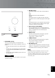
Controls and functions ■ Front panel (pages 6 to 9) RIGHT LEFT – 60 40 30 0.01 0.1 20 10 3 1 10 50 3 + 0 – 60 40 100 30 0.01 0.1 dB PHONES TRIM -6 0 SPEAKERS +6 OFF +12 A TREBLE 3 0 INPUT BAL 2 BAL 1 LINE 1 A+B BI-WIRING TUNER LINE 2 – + – + L A A Remote control sensor Receives signals from the remote control. y The remote control transmits a directional infrared beam.
E AUDIO MUTE indicator Lights when the mute function is turned on with the AUDIO MUTE switch. F VOLUME control Controls the volume level. This does not affect the output level at the LINE 2 REC jacks. VOLUME Note 3 0 3 + The VOLUME control does not affect when you select MAIN DIRECT as the input source. Adjust the volume level using the volume control on the external amplifier connected to the MAIN IN jacks.
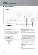
Controls and functions ■ Rear panel 1 3 2 4 5 6 AUTO POWER STANDBY GND PHONO ON BAL 1 TUNER OFF BAL 2 LINE 1 CD NORMAL(EIA) SPEAKERS R CH ATTENUATOR BYPASS ATT. (-6DB) PHASE NORMAL INV. ATTENUATOR BYPASS ATT. (-6DB) PHASE NORMAL INV. +HOT 2 1 3 - COLD SYSTEM CONNECTOR REMOTE IN OUT TRIGGER IN AC IN D E A OR B:4 MIN./SPEAKER A + B:8 MIN.
A SPEAKERS L/R CH terminals 7 8 9 0 AUTO POWER STANDBY ON OFF LINE 2 LINE 1 REC PRE OUT MAIN IN PB NORMAL(EIA) SPEAKERS L CH ASE INV. +HOT 2 1 GND B SYSTEM CONNECTOR Use this connector to connect a product testing device for servicing. C REMOTE IN/OUT jacks Use these jacks to connect an external component for remote control. For details on the connection, see page 21. D TRIGGER IN jack Use this jack to connect an external component for the trigger function.
Controls and functions ■ Remote control 1 1 Infrared signal transmitter Outputs infrared control signals. 2 2 p AMP key Turns this unit ON or switches it to STANDBY mode. For details on STANDBY mode, see “Front panel” (page 6). AMP OPEN/CLOSE 1 CD 2 5 6 BAL 1 3 2 LINE PHONO MAIN DIRECT CD TUNER When LINE 2 is selected as the input source, the audio signals are not output at the LINE 2 REC jacks.
5 p CD key Turns the Yamaha CD player ON or switches it to STANDBY mode. 8 VOLUME +/– keys Control the volume level. Note 6 OPEN/CLOSE key Opens/closes the disc tray of the Yamaha CD player. Refer to the owner’s manual of your CD player for details. Note Some Yamaha CD players do not support the CD key and/or OPEN/CLOSE key of this remote control. The VOLUME keys do not affect when you select MAIN DIRECT as the input source.
Controls and functions ■ Installing batteries in the remote control 1 Remove the battery compartment cover. 2 Insert the two batteries (AAA, R03, UM-4) according to the polarity markings (+ and -) on the inside of the battery compartment. 1 2 3 Reinstall the battery compartment cover.
Connections In this section, you will make connections between A-S3000, speakers, and source components.
Connections Turntable Speakers A (R channel) Ground + - AUTO POWER STANDBY GND PHONO ON TUNER OFF BAL 2 BAL 1 LINE CD NORMAL SPEAKERS R CH ATTENUATOR BYPASS ATT. (-6dB) PHASE NORMAL INV. ATTENUATOR BYPASS ATT. (-6dB) PHASE NORMAL INV. +HOT 2 1 3 - COL SYSTEM CONNECTOR REMOTE IN OUT TRIGGER IN AC IN A OR B:4 MIN./SPEAKER A + B:8 MIN.
Preamplifier, AV receiver, etc. CD recorder, tape deck, etc. External amplifier or active subwoofer Speakers A (L channel) - + AUTO POWER STANDBY ON BAL 1 OFF BAL 2 LINE 2 LINE 1 REC PRE OUT MAIN IN PB NORMAL(EIA) ATOR ATT. (-6DB) PHASE NORMAL INV. ATTENUATOR BYPASS ATT. (-6dB) SPEAKERS L CH PHASE NORMAL INV. +HOT 2 1 GND 3 - COLD AC IN A OR B:4 MIN./SPEAKER A + B:8 MIN./SPEAKER – Network player with XLR jacks + Speakers B (L channel) BD player, etc. Caution Fig.
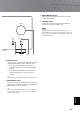
Connections ■ Connecting the speakers ■ Connecting the banana plug (Except for Europe models) 1 Remove approximately 10 mm of insulation from the end of each speaker cable and twist the exposed wires of the cable together to prevent short circuits. First, tighten the knob and then insert the banana plug into the end of the corresponding terminal. 10 mm Banana plug 2 Unscrew the knob and then insert the bare wire into the hole. Hole for banana plug: 5.5 mm dia.
■ Bi-wire connection ■ Connecting the power cable The bi-wire connection separates the woofer from the combined midrange and tweeter section. A bi-wire compatible speaker has four binding post terminals. These two sets of terminals allow the speaker to be split into two independent sections. This split connects the mid and high frequency drivers to one set of terminals and the low frequency driver to the other pair.
Connections ■ Connecting to the BAL 1/BAL 2 jacks Connect your CD player or network player with the XLR balanced output jacks. Set the ATTENUATOR selector and PHASE selector located below the BAL 1 or BAL 2 jacks according to the component to be connected. ATTENUATOR selector: Select the allowable input level for the XLR balanced input jacks. If sound from the connected component is distorted, set the ATTENUATOR selector to ATT. (-6 dB).
■ Operating this unit from another room If you connect an infrared receiver and transmitter to the REMOTE IN/OUT jacks of this unit, you can operate the unit and/or external component using the supplied remote control located in another room. Infrared receiver REMOTE IN OUT When you have another Yamaha component supporting remote connection, as this unit does, an infrared transmitter is not necessary.
Connections ■ Connecting a component supporting the trigger function such as a Yamaha AV receiver The operations of this unit can be controlled in synchronization with the operations of the connected component, such as a Yamaha AV receiver (power ON/ STANDBY or MAIN DIRECT input selection).
Specifications In this section, you will find technical specifications for A-S3000.
Specifications POWER SECTION CONTROL SECTION • Rated Output Power (8 Ω , 20 Hz to 20 kHz, 0.07% THD) ...................... 90 W + 90 W (4 Ω , 20 Hz to 20 kHz, 0.07% THD) .................. 145 W + 145 W • Input Sensitivity/Input Impedance CD, etc. ........................................................... 200 mVrms/47 kΩ PHONO MM ................................................... 2.5 mVrms/47 kΩ PHONO MC ...................................................... 100 μVrms/50 Ω MAIN IN ....................
■ Block diagram BAL 1 BAL 2 HOT (+) COLD (-) HOT (+) COLD (-) Phase change (normal / inv.) UNBALANCE CONVERTER COLD (-) HOT (+) BALANCE BALANCE GAIN SEL INPUT SELECTOR MM EQ AMP MC HEAD AMP MM//MC FOR MC AMP VOLUME ATT.UINT1 ATT.UINT2 ATT.UINT3 ATT.UINT1 ATT.UINT2 ATT.
Specifications ■ Tone control characteristics 14 12 10 8 6 Response (dB) 4 2 0 –2 –4 –6 –8 –10 –12 –14 10 20 30 50 100 200 300 500 1k 2k 3k 5k 10k 20k 30k Frequency (Hz) ■ Total harmonic distortion 1.000 0.500 0.200 THD + N Ratio (%) 0.100 0.050 20kHz 0.020 20Hz 0.010 0.005 1kHz 0.002 0.
■ Total harmonic distortion (PHONO) 10 5 3 2 1 THD + N Ratio (%) 0.5 0.3 0.2 0.1 0.05 20Hz 0.03 0.02 1kHz 20kHz 0.01 0.005 0.003 0.002 0.001 0.0005 0.0003 0.0002 0.
Troubleshooting Refer to the chart below if this unit does not function properly. If the problem you are experiencing is not listed below or if the instructions below do not help, turn off this unit, disconnect the power cable, and contact the nearest authorized Yamaha dealer or service center. Problem Cause Remedy See page The power cable is not connected to the AC IN inlet on the rear panel or not plugged in the AC wall outlet. Connect the power cable firmly.
Problem Cause Remedy See page The sound from the component connected to the BAL 1/BAL 2 jacks is degraded. The sound level is higher than the maximum input level for the XLR balanced input jacks. If the output level of the connected component is double, set the ATTENUATOR selector located below the input jacks to ATT. (-6 dB). Bass is not spatial when BAL 1/BAL 2 (balanced input) is selected. The polarity is incorrect. Select the correct polarity with the PHASE selector.
Historia viva en el mundo del sonido El nacimiento de un piano es el resultado de una perfecta sinergia entre los conocimientos técnicos más avanzados y la diestra mano del artesano. Solo un piano creado así puede reproducir fielmente la intención de quien lo toca. La última fase de producción de un piano recibe el nombre de “armonización” (voicing). Y es aquí donde se le infunde el alma.
Excelencia en audio Primer sistema HiFi presentado en 1920 En 1955 – 1965 hemos presentado numerosos componentes HiFi (giradiscos, sintonizadores de FM/AM, amplificadores integrados, preamplificadores, amplificadores de potencia, y altavoces). Serie de Altavoces Natural Sound presentada en 1967 Altavoz monitor NS-20 Amplificador integrado CA-1000 Con un funcionamiento clase A, el CA-1000 se convirtió en la referencia de los amplificadores integrados.
◆ Diseño de circuito completamente flotante y equilibrado que permite aprovechar todo el potencial de la amplificación analógica Un amplificador de potencia flotante y equilibrado completamente nuevo que logra la simetría completa y permite la transmisión (amplificación) completamente equilibrada desde el jack de entrada hasta justo antes del jack del altavoz.
Controles y funciones En este capítulo podrá familiarizarse con los controles y funciones del A-S3000.
Controles y funciones ■ Panel delantero (páginas 6 a 9) LEFT – 60 40 30 0.01 0.1 20 RIGHT 10 3 1 10 50 3 + 0 – 60 40 100 30 0.01 0.1 dB PHONES -6 TRIM SPEAKERS 0 A +6 OFF B 3 1 10 50 TREBLE 0 3 + 100 INPUT BALANCE BAL 2 METER OFF PEAK VU BAL 1 CD LINE 1 A+B BI-WIRING +12 10 dB BASS STANDBY/ON 20 LINE 2 – 1 2 3 4 5 6 1 Interruptor STANDBY/ON/OFF Enciende o apaga esta unidad.
VOLUME 3 0 3 + 0 100 INPUT BAL 1 CD PHONO MM TUNER AUDIO MUTE PHONO MC 6 Selector METER Permite seleccionar las opciones OFF, PEAK o VU del indicador. OFF: Apaga el indicador y la iluminación. PEAK: Activa el indicador de nivel máximo. El indicador de nivel máximo muestra un nivel de salida de audio puntualmente muy alto. VU: Activa el indicador de nivel VU (unidad de volumen). El indicador de nivel VU muestra un nivel de salida de audio efectivo similar a la percepción humana.
Controles y funciones ■ Panel delantero (páginas 6 a 9) RIGHT LEFT – 60 40 30 0.01 0.1 20 10 3 1 10 50 3 + 0 – 60 40 100 30 0.01 0.1 dB PHONES TRIM -6 0 SPEAKERS +6 OFF +12 A B 10 3 1 10 50 0 TREBLE INPUT BALANCE BAL 2 METER OFF PEAK VU BAL 1 LINE 1 A+B BI-WIRING TUNER LINE 2 – + – + L A A Sensor de mando a distancia Recibe señales del mando a distancia. y El mando a distancia transmite una rayo infrarrojo direccional.
E Indicador AUDIO MUTE Se ilumina al activar la función de silencio con el interruptor AUDIO MUTE. F Control VOLUME Controla el nivel del sonido. No afecta al nivel de salida por los jacks LINE 2 REC. VOLUME Nota 3 0 3 + El control VOLUME no tienen ningún efecto al seleccionar MAIN DIRECT como fuente de entrada. Ajuste el nivel de volumen con el control de volumen del amplificador externo conectado a los jacks MAIN IN.
Controles y funciones ■ Panel trasero 1 3 2 4 5 6 AUTO POWER STANDBY GND PHONO ON BAL 1 TUNER OFF BAL 2 LINE 1 CD NORMAL(EIA) SPEAKERS R CH ATTENUATOR BYPASS ATT. (-6DB) PHASE NORMAL INV. ATTENUATOR BYPASS ATT. (-6DB) PHASE NORMAL INV. +HOT 2 1 3 - COLD SYSTEM CONNECTOR REMOTE IN OUT TRIGGER IN AC IN D E A OR B:4 MIN./SPEAKER A + B:8 MIN./SPEAKER A B Consulte la página 16 para obtener información sobre las conexiones.
A Terminales SPEAKERS L/R CH 7 8 9 0 AUTO POWER STANDBY ON OFF LINE 2 LINE 1 REC PRE OUT MAIN IN B SYSTEM CONNECTOR Utilice este conector para conectar un dispositivo para probar el producto al realizar operaciones de mantenimiento. C Jacks REMOTE IN/OUT Utilice estos jacks para conectar un componente externo utilizado como mando a distancia. Para obtener más información sobre la conexión, consulte la página 21. PB NORMAL(EIA) SPEAKERS L CH ASE INV. +HOT 2 1 GND 3 - COLD A OR B:4 MIN.
Controles y funciones ■ Mando a distancia 1 1 Transmisor de señal infrarroja Envía señales infrarrojas de control a esta unidad. 2 2 Tecla p AMP Enciende esta unidad o activa el modo STANDBY. Para obtener más información sobre el modo STANDBY, consulte “Panel delantero” (página 6). AMP OPEN/CLOSE 1 CD 2 5 6 BAL 1 3 2 LINE PHONO MAIN DIRECT CD TUNER Al seleccionar LINE 2 como fuente de entrada, no se emiten señales de audio por los jacks LINE 2 REC.
5 Tecla p CD Enciende el reproductor de CD Yamaha o activa el modo STANDBY. 8 Teclas VOLUME +/– Controlan el nivel de volumen. Nota 6 Tecla OPEN/CLOSE Abre y cierra la bandeja del disco del reproductor de CD Yamaha. Con respecto a los detalles, consulte el manual del usuario del reproductor de CD. Nota Algunos reproductores de CD Yamaha no son compatibles con la tecla CD y/o la tecla OPEN/CLOSE de este mando a distancia.
Controles y funciones ■ Instalación de las pilas en el mando a distancia 1 Retire la tapa del compartimento de las pilas. 2 Introduzca las dos pilas (AAA, R03, UM-4) teniendo en cuenta las marcas de polaridad (+ y -) del interior del compartimento de las pilas. 1 2 3 Vuelva a colocar la tapa del compartimento de las pilas.
Conexiones En esta sección hará las conexiones entre el A-S3000, los altavoces y los componentes fuente.
Conexiones Giradiscos Altavoces A (Canal R) Tierra + - AUTO POWER STANDBY GND PHONO ON TUNER OFF BAL 2 BAL 1 LINE CD NORMAL SPEAKERS R CH ATTENUATOR BYPASS ATT. (-6dB) PHASE NORMAL INV. ATTENUATOR BYPASS ATT. (-6dB) PHASE NORMAL INV. +HOT 2 1 3 - COL SYSTEM CONNECTOR REMOTE IN OUT TRIGGER IN AC IN A OR B:4 MIN./SPEAKER A + B:8 MIN.
Preamplificador, receptor AV, etc. Grabadora de CD, pletina de casete, etc. Amplificador externo o altavoz de subgraves activo Altavoces A (Canal L) - + AUTO POWER STANDBY ON BAL 1 OFF BAL 2 LINE 2 LINE 1 REC PRE OUT MAIN IN PB NORMAL(EIA) ATOR ATT. (-6DB) PHASE NORMAL INV. ATTENUATOR BYPASS ATT. (-6dB) SPEAKERS L CH PHASE NORMAL INV. +HOT 2 GND 1 3 - COLD AC IN A OR B:4 MIN./SPEAKER A + B:8 MIN.
Conexiones ■ Conexión de altavoces ■ Conexión de la clavija tipo banana (Excepto los modelos para Europa) 1 Quite aproximadamente 10 mm de aislamiento del extremo de cada cable de altavoz y luego retuerza juntos los hilos expuestos del cable para evitar cortocircuitos. Primero apriete la perilla y luego inserte la clavija tipo banana en el extremo del terminal correspondiente. 10 mm Clavija tipo banana Orificio para la clavija tipo banana: 5,5 mm diá.
■ Conexión bicable ■ Conexión del cable de alimentación La conexión bicable separa el altavoz de subgraves de la sección combinada de altavoz de gama central y altavoz de agudos. Un altavoz compatible con bicable tiene cuatro terminales tipo borne. Estos dos juegos de terminales permiten dividir el altavoz en dos secciones independientes. Con esta división se conectan las bocinas de frecuencia media y alta a un juego de terminales y la bobina de baja frecuencia al otro par.
Conexione ■ Conexión a los jacks BAL 1/BAL 2 Conecte su reproductor de CD o su reproductor de red con los jacks de salida equilibrada XLR. Configure el selector ATTENUATOR y el selector PHASE situados debajo de los jacks BAL 1 o BAL 2 según el componente conectado. Selector ATTENUATOR: Seleccione el nivel de entrada permitido para los jacks de entrada equilibrada XLR. Si el sonido del componente conectado sale distorsionado, sitúe el selector ATTENUATOR en la posición ATT. (-6 dB).
■ Control de esta unidad desde otra habitación ■ Conexión remota entre componentes Yamaha Si conecta un receptor y un transmisor de señales infrarrojas a los jacks REMOTE IN/OUT de esta unidad, podrá controlar la unidad y/o un componente externo con el mando a distancia suministrado desde otra habitación. Si tiene otro componente Yamaha compatible con la conexión remota, como esta unidad, no es necesario el transmisor de señales infrarrojas.
Conexiones ■ Conexión de un componente compatible con la función de activación, como un receptor AV Yamaha Las operaciones de esta unidad pueden controlarse de forma sincronizada con las operaciones del componente conectado, como un receptor AV Yamaha (alimentación ON/STANDBY o selección de la entrada MAIN DIRECT).
Especificaciones En esta sección encontrará las especificaciones técnicas del A-S3000.
Especificaciones SECCIÓN DE ALIMENTACIÓN SECCIÓN DE CONTROL • Potencia de salida nominal (8 Ω , 20 Hz a 20 kHz, 0,07% THD) ....................... 90 W + 90 W (4 Ω , 20 Hz a 20 kHz, 0,07% THD) ................... 145 W + 145 W • Sensibilidad de entrada/Impedancia de entrada CD, etc. ........................................................... 200 mVrms/47 kΩ PHONO MM ................................................... 2,5 mVrms/47 kW PHONO MC ......................................................
■ Diagrama en bloques BAL 1 BAL 2 HOT (+) COLD (-) HOT (+) COLD (-) Phase change (normal / inv.) UNBALANCE CONVERTER COLD (-) HOT (+) BALANCE BALANCE GAIN SEL INPUT SELECTOR MM EQ AMP MC HEAD AMP MM//MC FOR MC AMP VOLUME ATT.UINT1 ATT.UINT2 ATT.UINT3 ATT.UINT1 ATT.UINT2 ATT.
Especificaciones ■ Características de control de tono 14 12 10 8 6 Response (dB) 4 2 0 –2 –4 –6 –8 –10 –12 –14 10 20 30 50 100 200 300 500 1k 2k 3k 5k 10k 20k 30k Frequency (Hz) ■ Distorsión armónica total 1.000 0.500 0.200 THD + N Ratio (%) 0.100 0.050 20kHz 0.020 20Hz 0.010 0.005 1kHz 0.002 0.
■ Distorsión armónica total (PHONO) 10 5 3 2 1 THD + N Ratio (%) 0.5 0.3 0.2 0.1 0.05 20Hz 0.03 0.02 1kHz 20kHz 0.01 0.005 0.003 0.002 0.001 0.0005 0.0003 0.0002 0.
Solución de problemas Consulte la tabla de abajo si esta unidad no funciona correctamente. Si el problema que tiene no está en la lista que aparece a continuación o las instrucciones siguientes no le sirven de ayuda, apague esta unidad, desconecte el cable de alimentación y póngase en contacto con el centro de servicio o distribuidor Yamaha autorizado más cercano.
Vea la página Problema Causa Remedio Faltan tonos graves y no hay sonido ambiental. Los cables + y – están conectados al revés al amplificador o a los altavoces. Conecte los cables de los altavoces a los terminales + y – correctos. Se oye un sonido de zumbido. Las conexiones de los cables están mal hechas. Conecte firmemente las clavijas del cable de audio. Si sigue habiendo problemas, los cables están en mal estado. 16 No hay conexión del giradiscos al terminal GND.
L Integrated Amplifier OWNER’S MANUAL MANUAL DE INSTRUCCIONES © 2013 Yamaha Corporation Printed in Malaysia ZK04740-2