x PREFACE This manual has been prepared by Yamaha primarily for use by Yamaha dealers and their trained mechanics when performing maintenance procedures and repairs to Yamaha equipment. It is not possible to put an entire mechanic’s education into one manual, so it is assumed that persons using this book to perform maintenance and repairs on Yamaha machines have a basic understanding of the mechanical concepts and procedures inherent in machine repair technology.
HOW TO USE THIS MANUAL MANUAL FORMAT All of the procedures in this manual are organized in a sequential, step-by-step format. The information has been compiled to provide the mechanic with an easy-to-read, handy reference that contains comprehensive explanations of all disassembly, repair, assembly, and inspection operations. In this revised format, the condition of a faulty component will precede an arrow symbol and the course of action required will follow the symbol, e.g.
HOW TO READ DESCRIPTIONS 1. A disassembly/installation job instruction mainly consists of the exploded diagram 1. 2. The numerical figures represented by the number 2 indicates the order of the job steps. 3. The symbols represented by the number 3 indicates the contents and notes of the job. For the meanings of the symbols, refer to the next page(s). 4. The REMOVAL AND INSTALLATION CHART 4 is attached to the exploded diagram and explains the job steps, part names, notes for the jobs, etc. 5.
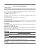
SYMBOLS Symbols 1 to 9 are designed as thumb-tabs to indicate the content of a chapter: 1 2 3 4 5 6 7 8 9 HULL DECK General Information Specifications Periodic Inspection and Adjustment Fuel System Power Unit Jet Pump Unit Electrical System Hull and Deck Trouble Analysis Symbols 10 to 15 indicate specific data: 10 Special Tool 11 Specified Liquid 12 Specified Engine Speed 13 Specified Torque 14 Specified Measurement 15 Specified Electrical Valve [Resistance (Ω), Voltage (V), Electric Current (A)] Symbol
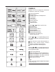
INDEX GEN INFO GENERAL INFORMATION 1 SPEC SPECIFICATIONS 2 INSP ADJ PERIODIC INSPECTION AND ADJUSTMENT 3 FUEL FUEL SYSTEM 4 POWR POWER UNIT 5 JET PUMP JET PUMP 6 ELEC ELECTRICAL SYSTEM 7 HULL DECK HULL AND DECK 8 TRBL ANLS TROUBLE ANALYSIS 9
x CHAPTER 1 GENERAL INFORMATION IDENTIFICATION NUMBERS . . . . . . . . . . . . . . . . . . . . . . . . . . . . . . . . . . . . . . . . . . . . . . . . 1-1 PRIMARY I.D. NUMBER . . . . . . . . . . . . . . . . . . . . . . . . . . . . . . . . . . . . . . . . . . . . . . . . . 1-1 ENGINE SERIAL NUMBER . . . . . . . . . . . . . . . . . . . . . . . . . . . . . . . . . . . . . . . . . . . . . . 1-1 HULL IDENTIFICATION NUMBER (H.I.N.) . . . . . . . . . . . . . . . . . . . . . . . . . . . . . . . . . .
GENERAL INFORMATION x GEN INFO 1 A60700-0* IDENTIFICATION NUMBERS PRIMARY I.D. NUMBER The primary I.D. number is stamped on a label attached to the deck under the rear seat. Starting Primary I.D. Number: SRT1100-D/SX230HO F1U-700101 SRT1100 A-D/AR230HO. F1U-720101 ENGINE SERIAL NUMBER The engine serial number is stamped on a label attached to the crankcase. Starting Engine Serial Number: 6P6: 1000401 HULL IDENTIFICATION NUMBER (H.I.N.) The H.I.N.
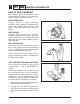
1 GEN INFO GENERAL INFORMATION SAFETY WHILE WORKING The procedures given in this manual are those recommended by Yamaha to be followed by Yamaha dealers and their mechanics. FIRE PREVENTION Gasoline (petrol) is highly flammable. Petroleum vapor is explosive if ignited. Do not smoke while handling gasoline (petrol), and keep it away from heat, sparks, and open flames. VENTILATION Petroleum vapor is heavier than air and if inhaled in large quantities will not support life.
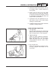
GENERAL INFORMATIONx GEN INFO 1 3. Avoid skin contact with lubricants; do not, for example, place a soiled wiping-rag in one’s pocket. 4. Hands, and any other part of the body which have been in contact with lubricants or lubricant-contaminated clothing, should be thoroughly washed with hot water and soap as soon as practicable. 5. To protect the skin, the application of a suitable barrier cream to the hands before working is recommended. 6.
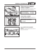
1 GEN INFO GENERAL INFORMATION DISASSEMBLY AND ASSEMBLY 1. Clean parts with solvent and compressedair on disassembling them. 2. Oil the contact surfaces of moving parts on assembly. 3. After assembly, check that moving parts operate normally. 4. Install bearings with the manufacturer’s markings on the side exposed to view and liberally oil the bearings. CAUTION: Do not use compressed air to spin the bearings dry. This causes damage to the bearing surfaces. 5.
GENERAL INFORMATIONx GEN INFO 1 SPECIAL TOOLS Use of the correct special tools recommended by Yamaha will aid the work and enable accurate assembly and tune-up. Improvisations and use of improper tools can cause damage to the equipment. NOTE: • For U.S.A. and Canada, use part numbers starting with “J-”, “YB-”, “YM-”,“YS-”, “YU-” or “YW-”. • For other countries, use part numbers starting with “90890-.
1 GEN INFO GENERAL INFORMATION SPECIAL TOOLS 11 Fuel Pressure Gauge P/N YB-06766 90890-06786 12 Compression Gauge Extension P/N 90890-06582 13 Cylinder Gauge Set P/N YU-03017 90890-06759 14 Compression Gauge P/N YU-33223-1 90890-03160 15 Peak Voltage Adapter P/N YU-39991 90890-03172 16 Spark Gap Tester P/N YM34487 90890-06754 17 Test Harness (2 pins) P/N YB-06792 90890-06792 18 Test Harness (3 pins) P/N YB-06791 90890-06791 19 Test Harness (3 pins) P/N YB-06770 90890-06770 20 Test Harn
GENERAL INFORMATIONx GEN INFO 1 SPECIAL TOOLS YB-06769 90890-06769 YB-35956-A 90890-06756 23 Test Harness (3 pins) P/N YB-06769 90890-06769 24 Vacuum/Pressure Pump Gauge Set P/N YB-35956-A 90890-06756 25 Yamaha Diagnostic System for Watercraft P/N LIT-YDIS1-23-00 26 Yamaha Diagnostic System Connector for Watercraft P/N 60V-WS850-00-00 USB Cable P/N 68F-WS850-00-00 Serial Cable LIT-YDIS1-21-00 60V-85300-01 -WS853-01 60V 60V-WS850-00-00 USB Cable / 68F-WS850-00-00 Serial Cable YAMAHA DIAGNOSTIC
1 GEN INFO GENERAL INFORMATION REMOVAL AND INSTALLATION TOOLS YU-38411 90890-01426 YW-06551 1 Oil Filter Wrench P/N YU-38411 90890-01426 90890-06551 2 Coupler Wrench P/N YW-06551 90890-06551 YS-01880-A 90890-01701 YM-01082 90890-01080 3 Sheave Holder P/N YS-01880-A 90890-01701 4 Rotor Puller P/N YM-01082 90890-01080 YU-01235 90890-01235 YM-45469 90890-04019 5 Rotor Holder P/N YU-01235 90890-01235 6 Valve Remover/Installer Kit P/N YM-45469 90890-04019 YM-4114 (¯19 mm ) 90890-04114 (¯19 mm) YM-41
GENERAL INFORMATIONx 11 GEN INFO 1 Valve Seat Cutter Intake P/N 90890-06813 (60°) 90890-06814 (45°) 90890-06815 (30°) Exhaust P/N 90890-06315 (60°) 90890-06312 (45°) 90890-06328 (30°) 1-9 12 Valve Seat Cutter Holder P/N 90890-06811 (ø4.0 mm) 90890-06812 (ø4.
1 GEN INFO GENERAL INFORMATION 1-10
CHAPTER 2 SPECIFICATIONS GENERAL SPECIFICATIONS . . . . . . . . . . . . . . . . . . . . . . . . . . . . . . . . . . . . . . . . . . . . . . . . . . 2-1 MAINTENANCE SPECIFICATIONS . . . . . . . . . . . . . . . . . . . . . . . . . . . . . . . . . . . . . . . . . . . . . 2-3 ENGINE . . . . . . . . . . . . . . . . . . . . . . . . . . . . . . . . . . . . . . . . . . . . . . . . . . . . . . . . . . . . . 2-3 JET PUMP UNIT . . . . . . . . . . . . . . . . . . . . . . . . . . . . . . . . . . . . . . . . . . . . . .
SPECIFICATIONSx SPEC GENERAL SPECIFICATIONS SRT1100 F1U 6P6 SX: 2.1 (6.92 ft); AR: 3.1 (10.3 ft) SX: 1372 (3025 lb); AR: 1406 (3100 lb) 117.7 (160) @ 10,000 45 (11.9, 9.9) 1.56 1,052 (64.2) 76.0 x 58.0 (2.99 x 2.28) 11.9:1 BTDC 5-BTDC 32 Jet thrust nozzle trim angle Impeller pitch Degree Degree +3 Port 18.1° / Stbd. 15.
2 SPEC SPECIFICATIONS GENERAL SPECIFICATIONS SRT1100 SE, SF, SG, SH, SJ, SL L (US qt, Imp qt) L (US qt, Imp qt) L (US qt, Imp qt) 2-2
SPECIFICATIONSx SRT1100 2-3 SPEC 2
2 SPEC SPECIFICATIONS MAINTENANCE SPECIFICATIONS SRT1100 0.020–0.047 (0.0008–0.0019) 16.971 (0.
SPECIFICATIONSx SRT1100 6P601 2-5 SPEC 2
2 SPEC SPECIFICATIONS MAINTENANCE SPECIFICATIONS SRT1100 SRT1100 Port 18.1 Stbd. 15.1 SRT1100 Marine Group 24 Dual Purpose 675 CCA 100 (12/68.
SPECIFICATIONSx MAINTENANCE SPECIFICATIONS SRT1100 2-7 SPEC 2
2 SPEC SPECIFICATIONS MAINTENANCE SPECIFICATIONS SRT1100 2-8
SPECIFICATIONSx Screw 1/4-20 16 Nut 8-32 10-24 6 5 Fuel sender 2-9 4.9 7.9 2.3 2.9 0.49 0.79 0.23 0.29 SPEC 3.5 5.6 1.6 2.
2 SPEC SPECIFICATIONS TIGHTENING TORQUES 2-10
SPECIFICATIONSx TIGHTENING TORQUES 2-11 SPEC 2
2 SPEC SPECIFICATIONS TIGHTENING TORQUES 2-12
SPEC SPECIFICATIONSx TIGHTENING TORQUES M8 2-13 6 20 2.0 14 3 20 2.
2 SPEC SPECIFICATIONS TIGHTENING TORQUES Part To Be Tightened Water inlet cover/water inlet strainer - impeller duct Drive shaft nut - drive shaft Impeller (left-hand threads) – drive shaft Intermediate housing - bulkhead Driven coupling - shaft Grease nipple - intermediate housing Hull: Steering cable locknut (jet thrust nozzle side) Steering cable grommet – hull Pilot water outlet - hull Engine mount – hull Engine damper – hull Electrical: Electrical box - bulk head Terminal cover - electrical box Cove
SPEC SPECIFICATIONSx 2 TIGHTENING TORQUES Part To Be Tightened Main and fuel pump relay Rectifier/regulator Ignition coil - oil tank Ignition coil cover - ignition coil case Part Name Tapping screw Tapping screw Bolt Tapping screw Thread size Qty ø6 1 2-15 Tightening Torque N•m kgf•m ft•lb 3.9 0.39 2.8 ø6 2 3.9 0.39 2.8 M6 ø6 3 10 7.6 4.9 0.76 0.49 5.5 3.
2 SPEC Nut A 8 mm 10 mm 12 mm 14 mm 17 mm SPECIFICATIONS GENERAL TORQUE General Torque Specifications Bolt B M5 M6 M8 M10 M12 Nm M•kg ft•lb 5.0 8.0 18 36 43 0.5 0.8 1.8 3.6 4.3 3.6 5.8 13 25 31 This chart specifies the torques for tightening standard fasteners with standard clean dry ISO threads at room temperature. Torque specifications for special components or assemblies are given in applicable sections of this manual.
SPECIFICATIONSx CABLE AND HOSE ROUTING 2-17 SPEC 2
2 SPEC SPECIFICATIONS CABLE AND HOSE ROUTING 2-18
SPECIFICATIONSx CABLE AND HOSE ROUTING 2-19 SPEC 2
2 SPEC SPECIFICATIONS CABLE AND HOSE ROUTING 2-20
SPECIFICATIONSx CABLE AND HOSE ROUTING 2-21 SPEC 2
2 SPEC SPECIFICATIONS CABLE AND HOSE ROUTING 2-22
CHAPTER 3 PERIODIC INSPECTION AND ADJUSTMENT MAINTENANCE INTERVAL CHART . . . . . . . . . . . . . . . . . . . . . . . . . . . . . . . . . . . . . . . . . . . . . 3-1 PERIODIC SERVICE . . . . . . . . . . . . . . . . . . . . . . . . . . . . . . . . . . . . . . . . . . . . . . . . . . . . . . . . . 3-2 CONTROL SYSTEM . . . . . . . . . . . . . . . . . . . . . . . . . . . . . . . . . . . . . . . . . . . . . . . . . . . . 3-2 Remote Control Unit . . . . . . . . . . . . . . . . . . . . . . . . . . . . . . . . . .
PERIODIC INSPECTION AND ADJUSTMENT x 3-1 INSP ADJ 3
3 INSP ADJ PERIODIC INSPECTION AND ADJUSTMENT PERIODIC SERVICE CONTROL SYSTEM Steering helm inspection 1. Check: ● Friction Excessively heavy ➔ Replace the steering helm unit. 2. Check: ● Free play Excessive free play ➔ Replace the steering helm unit. Steering cable adjustment 1. Measure: ● Distance between the center of the steering nozzle joint and the cooling water casting boss on the right side of the pump. Incorrect distance ➔ Adjust steering cable joint at nozzle end.
PERIODIC INSPECTION AND ADJUSTMENT x INSP ADJ 3 REMOTE CONTROL UNIT Throttle Cables 1. Remove: • Airbox cover. 2. Set: • Remote Control levers to Neutral position. 3. Check: • Throttle Cable Wheel 1 should contact the idle screw and there should be free play in the cable. • If adjustment is necessary, loosen the Locknuts 2 at the throttle body end and turn the cable adjuster. 4. Tighten: • Locknuts 2 when adjustment is complete. 1 Cable Wheel 2 Locknuts 3 Throttle Cable Adjust Throttle Lever Stops: 1.
3 INSP ADJ PERIODIC INSPECTION AND ADJUSTMENT 3-4
PERIODIC INSPECTION AND ADJUSTMENT x 3-5 INSP ADJ 3
3 INSP ADJ PERIODIC INSPECTION AND ADJUSTMENT 3-6
PERIODIC INSPECTION AND ADJUSTMENT x INSP ADJ 3 • Valve clearance adjustment should be made on a cold engine at room temperature. • When the valve clearance is to be measured or adjusted, the piston must be at Top Dead Center (TDC) on the compression stroke.
3 INSP ADJ PERIODIC INSPECTION AND ADJUSTMENT 3-8
PERIODIC INSPECTION AND ADJUSTMENT x 3-9 INSP ADJ 3
3 INSP ADJ PERIODIC INSPECTION AND ADJUSTMENT Make a note of the position of each valve lifter 3 and valve pad 4 so they can be installed in the correct place.
PERIODIC INSPECTION AND ADJUSTMENT x 3-11 INSP ADJ 3
3 INSP ADJ PERIODIC INSPECTION AND ADJUSTMENT 3-12
PERIODIC INSPECTION AND ADJUSTMENT x CAUTION: 3-13 INSP ADJ 3
3 INSP ADJ PERIODIC INSPECTION AND ADJUSTMENT Place the craft in water, and then CAUTION: 3-14
PERIODIC INSPECTION AND ADJUSTMENT x INSP ADJ If the oil temperature is low, the reading on the dipstick will be low. If the temperature is high, the reading on the dipstick will be high. CAUTION: Do not run the engine for more than 15 seconds without supplying water when checking the oil level on land. The engine could overheat. craft in a horizontal position.
3 INSP ADJ PERIODIC INSPECTION AND ADJUSTMENT CAUTION: 3-16
PERIODIC INSPECTION AND ADJUSTMENT x INSP ADJ CAUTION: When starting the engine, make sure the dipstick is securely fitted into the oil tank.
3 INSP ADJ PERIODIC INSPECTION AND ADJUSTMENT CAUTION: Make sure the air filter element is installed in the filter case properly. If cleaning the air filter element, use cold or lukewarm water and let it air dry completely. Do not use detergent or a solvent to clean the air filter element, or dry it with heat or compressed air, otherwise it could be damaged.
PERIODIC INSPECTION AND ADJUSTMENT x 3-19 INSP ADJ 3
3 INSP ADJ PERIODIC INSPECTION AND ADJUSTMENT 3-20
PERIODIC INSPECTION AND ADJUSTMENT x 3-21 INSP ADJ 3
3 INSP ADJ PERIODIC INSPECTION AND ADJUSTMENT BILGE PUMP 1. Remove inspection cover in pump clean-out tray. 2. Inspect: • Bilge strainer Contaminants → Clean. Cracks/damage → Replace. Inspection Steps: • Install the coupling cover. Disconnect the bilge strainer from the bilge strainer holder.
PERIODIC INSPECTION AND ADJUSTMENT x 3-23 INSP ADJ 3
3 INSP ADJ PERIODIC INSPECTION AND ADJUSTMENT GENERAL Drain plug inspection 1. Inspect: ● Drain plug Crack/Damage ➔ Replace. ● O-Ring Crack/Wear ➔ Replace. ● Screw threads Dirt/Sand ➔ Clean. Greasing points 1. Apply: ● Throttle cable inner wire ● Shift control cable ● Cable joint ● Steering cable Recommended Grease: Water resistant grease NOTE: Remove the cable joint and apply a small amount of grease to the following parts.
PERIODIC INSPECTION AND ADJUSTMENT x INSP ADJ 3 Lubrication points 1. Lubricate: ● Throttle cable (throttle body end) Recommended lubricant: Yamaha marine grease, Yamaha grease A (Water resistant grease) NOTE: Before lubricating the QSTS control cables, remove the QSTS cable housing cover. Spray the rust inhibitor into the outer cables, and apply grease to the inner cables. 2.
3 INSP ADJ PERIODIC INSPECTION AND ADJUSTMENT 4.
CHAPTER 4 FUEL SYSTEM FUEL TANK AND FUEL PUMP MODULE EXPLODED DIAGRAM . . . . . . . . . . . . . . . . . . . . . . . . . . . . . . . . . . . . . . . . . . . . . . . . . . REMOVAL AND INSTALLATION CHART . . . . . . . . . . . . . . . . . . . . . . . . . . . . . . . . . . . . SERVICE POINTS . . . . . . . . . . . . . . . . . . . . . . . . . . . . . . . . . . . . . . . . . . . . . . . . . . . . . Fuel hose disconnection . . . . . . . . . . . . . . . . . . . . . . . . . . . . . . . . . . . . . . . . . . . . . .
FUEL FUEL SYSTEM x 6 1 3 7 2 5 4.9~7.9 Nm (50~80 kgf-cm) See Note 4 10 28 8 28 29 28 28 12 28 28 29 11 28 28 9 28 15 13 16 18 14 13 13 17 13 19 30 20 26 27 21 22 23 24 25 REMOVAL AND INSTALLATION CHART Step Procedure / Part Name Q’ty FUEL TANK PUMP MODULE Service Points Follow the “Step” order for removal.
4 FUEL FUEL SYSTEM FUEL TANK AND FUEL PUMP MODULE (Cont’d.
FUEL FUEL SYSTEM x 4 FUEL TANK AND FUEL PUMP MODULE (Cont’d.) 6 1 3 7 2 5 4 10 28 8 28 29 28 28 12 28 28 29 11 28 28 9 28 15 13 16 18 14 13 13 17 13 19 30 20 26 27 21 22 Step 26 27 Procedure / Part Name Filler Cap Assembly Gasket Q’ty 1 1 FUEL TANK 28 29 30 Screw, Machine 1/4” - 20 x 1” Fix, Fuel Tank Fuel Tank Assembly 8 2 1 23 24 25 Service Points Note: Deck must be cut at outline to access fuel tank for removal 4.9~7.
4 FUEL FUEL SYSTEM SYSTEM.” Screws Loosen the screws in the sequence shown.
FUEL SYSTEM x FUEL Screws 4.9 Nm (0.49 kgf-m) 7.9 Nm (0.8 kgf-m) SYSTEM.
4 FUEL FUEL SYSTEM 4-6
FUEL SYSTEM x FUEL INJECTION SYSTEM (Cont’d.
4 FUEL FUEL SYSTEM FUEL INJECTION SYSTEM (Cont’d.
FUEL SYSTEM x FUEL INJECTION SYSTEM (Cont’d.
4 FUEL FUEL SYSTEM FUEL INJECTION SYSTEM (Cont’d.
FUEL SYSTEM x FUEL INJECTION SYSTEM (Cont’d.
4 FUEL FUEL SYSTEM FUEL INJECTION SYSTEM (Cont’d.
FUEL SYSTEM x FUEL INJECTION SYSTEM (Cont’d.
4 FUEL FUEL SYSTEM FUEL INJECTION SYSTEM (Cont’d.
FUEL SYSTEM x CAUTION: 4-15 FUEL 4
4 FUEL FUEL SYSTEM CAUTION: 4-16
FUEL SYSTEM x CAUTION: 4-17 FUEL 4
4 FUEL FUEL SYSTEM CAUTION: 4-18
FUEL SYSTEM x CAUTION: 4-19 FUEL 4
4 FUEL FUEL SYSTEM CAUTION: 4-20
FUEL SYSTEM x 4-21 FUEL 4
4 FUEL FUEL SYSTEM CAUTION: 4-22
FUEL SYSTEM x 4-23 FUEL 4
4 FUEL FUEL SYSTEM 4-24
FUEL SYSTEM x 4-25 FUEL 4
5-21 5-21 5-22 5-22
OIL PUMP . . . . . . . . . . . . . . . . . . . . . . . . . . . . . . . . . . . . . . . . . . . . . . . . . . . . . . . . . . . . . . . . . EXPLODED DIAGRAM . . . . . . . . . . . . . . . . . . . . . . . . . . . . . . . . . . . . . . . . . . . . . . . . . REMOVAL AND INSTALLATION CHART . . . . . . . . . . . . . . . . . . . . . . . . . . . . . . . . . . . SERVICE POINTS . . . . . . . . . . . . . . . . . . . . . . . . . . . . . . . . . . . . . . . . . . . . . . . . . . . . Oil pump inspection . . . . . . . . .
5-63 5-63 5-63 5-65 5-65 5-65 5-66 5-68 5-68 5-68 5-70 5-70 5-71 5-71 5-72 5-73 5-75 5-76 5-78 5-80 5-80 5-80 5-85 5-85 5-86 5-86 5-87 5-90 5-90 5-90 5-92 5-92 5-93 5-94 5-96 5-97 5-99
5-103 5-103 5-103 5-104 5-104 5-104 5-107 5-108 5-108 5-108 5-110 5-110 5-110 COOLING WATER HOSE ..............................................................................
POWER UNIT x 5-1 POWR 5
5 POWR POWER UNIT ENGINE UNIT EXPLODED DIAGRAM 5-2
POWER UNIT x 5-3 POWR 5
5 POWR POWER UNIT CAUTION: 5-4
POWER UNIT x 5-5 POWR 5
5 POWR POWER UNIT CAUTION: 5-6
POWER UNIT x 5-7 POWR 5
5 POWR POWER UNIT 5-8
POWER UNIT x EXHAUST PIPE 3 (Cont’d.
5 POWR POWER UNIT EXHAUST PIPE 3 (Cont’d.
POWER UNIT x 5-11 POWR 5
5 POWR POWER UNIT EXHAUST PIPES 1 AND 2 (Cont’d.
POWER UNIT x 5-13 POWR 5
5 POWR POWER UNIT EXHAUST MANIFOLD (Cont’d.
POWER UNIT x 5-15 POWR 5
5 POWR POWER UNIT OIL TANK (Cont’d.
POWER UNIT x OIL TANK (Cont’d.
5 POWR POWER UNIT OIL TANK (Cont’d.
POWER UNIT x OIL TANK (Cont’d.
5 POWR POWER UNIT OIL TANK (Cont’d.
POWER UNIT x OIL TANK (Cont’d.
5 POWR POWER UNIT OIL TANK (Cont’d.
POWER UNIT x OIL TANK (Cont’d.
5 POWR POWER UNIT OIL TANK (Cont’d.
POWER UNIT x 5-25 POWR 5
5 POWR POWER UNIT OIL PUMP (Cont’d.
POWER UNIT x OIL PUMP (Cont’d.
5 POWR POWER UNIT OIL PUMP (Cont’d.
POWER UNIT x OIL PUMP (Cont’d.
5 POWR POWER UNIT OIL PUMP (Cont’d.
POWER UNIT x OIL PUMP (Cont’d.
5 POWR POWER UNIT 5-32
POWER UNIT x REDUCTION DRIVE GEAR (Cont’d.
5 POWR POWER UNIT REDUCTION DRIVE GEAR (Cont’d.
POWER UNIT x REDUCTION DRIVE GEAR (Cont’d.
5 POWR POWER UNIT REDUCTION DRIVE GEAR (Cont’d.
POWER UNIT x POWR REDUCTION DRIVE GEAR (Cont’d.
5 POWR POWER UNIT REDUCTION DRIVE GEAR (Cont’d.
POWER UNIT x REDUCTION DRIVE GEAR (Cont’d.
5 POWR POWER UNIT REDUCTION DRIVE GEAR (Cont’d.
POWER UNIT x 5-41 POWR 5
5 POWR POWER UNIT GENERATOR AND STARTER MOTOR (Cont’d.
POWER UNIT x GENERATOR AND STARTER MOTOR (Cont’d.
5 POWR POWER UNIT GENERATOR AND STARTER MOTOR (Cont’d.
POWER UNIT x GENERATOR AND STARTER MOTOR (Cont’d.
5 POWR POWER UNIT GENERATOR AND STARTER MOTOR (Cont’d.
POWER UNIT x GENERATOR AND STARTER MOTOR (Cont’d.
5 POWR POWER UNIT GENERATOR AND STARTER MOTOR (Cont’d.
POWER UNIT x 5-49 POWR 5
5 POWR POWER UNIT CAMSHAFTS (Cont’d.
POWER UNIT x CAMSHAFTS (Cont’d.
5 POWR POWER UNIT CAMSHAFTS (Cont’d.
POWER UNIT x CAMSHAFTS (Cont’d.
5 POWR POWER UNIT CAMSHAFTS (Cont’d.
POWER UNIT x CAMSHAFTS (Cont’d.
5 POWR POWER UNIT CAMSHAFTS (Cont’d.
POWER UNIT x CAMSHAFTS (Cont’d.
5 POWR POWER UNIT CAMSHAFTS (Cont’d.
POWER UNIT x CAMSHAFTS (Cont’d.
5 POWR POWER UNIT CAMSHAFTS (Cont’d.
POWER UNIT x CAMSHAFTS (Cont’d.
5 POWR POWER UNIT CAMSHAFTS (Cont’d.
POWER UNIT x Hanger 5-63 POWR 5
5 POWR POWER UNIT CYLINDER HEAD 5-64
POWER UNIT x CYLINDER HEAD (Con’t.
5 POWR POWER UNIT CYLINDER HEAD (Cont’d.
POWER UNIT x CYLINDER HEAD (Cont’d.
5 POWR POWER UNIT 5-68
POWER UNIT x VALVES AND VALVE SPRINGS 5-69 POWR 5
5 POWR POWER UNIT VALVES AND VALVE SPRINGS (Cont’d.
POWER UNIT x VALVES AND VALVE SPRINGS (Cont’d.
5 POWR POWER UNIT VALVES AND VALVE SPRINGS (Cont’d.
POWER UNIT x VALVES AND VALVE SPRINGS (Cont’d.
5 POWR POWER UNIT VALVES AND VALVE SPRINGS (Cont’d.
POWER UNIT x VALVES AND VALVE SPRINGS (Cont’d.
5 POWR POWER UNIT VALVES AND VALVE SPRINGS (Cont’d.
POWER UNIT x VALVES AND VALVE SPRINGS (Cont’d.
5 POWR POWER UNIT VALVES AND VALVE SPRINGS (Cont’d.
POWER UNIT x VALVES AND VALVE SPRINGS (Cont’d.
5 POWR POWER UNIT 5-80
POWER UNIT x CRANCASE (Cont’d.
5 POWR POWER UNIT CRANCASE (Cont’d.
POWER UNIT x CRANCASE (Cont’d.
5 POWR POWER UNIT CRANCASE (Cont’d.
POWER UNIT x CRANCASE (Cont’d.
5 POWR POWER UNIT CRANCASE (Cont’d.
POWER UNIT x CRANCASE (Cont’d.
5 POWR POWER UNIT CRANCASE (Cont’d.
POWER UNIT x CRANCASE (Cont’d.
5 POWR POWER UNIT CON 5-90
POWER UNIT x CONNECTING RODS AND PISTONS (Cont’d.
5 POWR POWER UNIT CONNECTING RODS AND PISTONS (Cont’d.
POWER UNIT x CONNECTING RODS AND PISTONS (Cont’d.
5 POWR POWER UNIT CONNECTING RODS AND PISTONS (Cont’d.
POWER UNIT x CONNECTING RODS AND PISTONS (Cont’d.
5 POWR POWER UNIT CONNECTING RODS AND PISTONS (Cont’d.
POWER UNIT x CONNECTING RODS AND PISTONS (Cont’d.
5 POWR POWER UNIT CONNECTING RODS AND PISTONS (Cont’d.
POWER UNIT x CONNECTING RODS AND PISTONS (Cont’d.
5 POWR POWER UNIT CONNECTING RODS AND PISTONS (Cont’d.
POWER UNIT x CONNECTING RODS AND PISTONS (Cont’d.
5 POWR POWER UNIT CONNECTING RODS AND PISTONS (Cont’d.
POWER UNIT x 5-103 POWR 5
5 POWR POWER UNIT CRANKSHAFT (Cont’d.
POWER UNIT x CRANKSHAFT (Cont’d.
5 POWR POWER UNIT CRANKSHAFT (Cont’d.
POWER UNIT x CRANKSHAFT (Cont’d.
5 POWR POWER UNIT 5-108
POWER UNIT x THERMOSTAT (Cont’d.
5 POWR POWER UNIT THERMOSTAT (Cont’d.
POWER UNIT x 5-111 POWR 5
CHAPTER 6 JET PUMP UNIT INTAKE GRATING . . . . . . . . . . . . . . . . . . . . . . . . . . . . . . . . . . . . . . . . . . . . . . . . . . . . . . . . . . . 6-1 EXPLODED DIAGRAM . . . . . . . . . . . . . . . . . . . . . . . . . . . . . . . . . . . . . . . . . . . . . . . . . . 6-1 REMOVAL AND INSTALLATION CHART . . . . . . . . . . . . . . . . . . . . . . . . . . . . . . . . . . . . 6-1 PUMP UNIT . . . . . . . . . . . . . . . . . . . . . . . . . . . . . . . . . . . . . . . . . . . . . . . . . . . . . . . . .
JET PUMP x JET PUMP 6 INTAKE GRATING EXPLODED DIAGRAM 5 LT 242 LT 2 4 242 3 LT 242 1 REMOVAL AND INSTALLATION CHART Step Procedure / Part Name Q’ty (ea) INTAKE GRATING REMOVAL 1 2 3 4 5 Screw Screw Intake Grating Screw Intake Duct Service Points Follow the left “Step” order for removal. 2 4 2 12 2 6-1 8 x 35mm 8 x 20mm Port and Starboard Units 8 x 40mm Port and Starboard Units Reverse the removal steps for installation. NOTE: Apply clear silicone before installing a duct into the hull.
6 JET PUMP JET PUMP Apply clear silicone as shown before installing Duct into hull. Install Duct and torque screws to 15Nm (1.5m-kg, 11 ft-lb).
JET PUMP x JET PUMP 6 PUMP UNIT EXPLODED DIAGRAM REMOVAL AND INSTALLATION CHART Step Procedure / Part Name Q’ty (ea.) PUMP UNIT REMOVAL 1 2 3 4 5 6 7 8 9 Shift Cable Joint Steering Cable Joint Bolt (with washer) Nozzle Dowel Pin Duct w/Driveshaft and Impeller Bolt (with washer) Dowel Pin Impeller Housing Assembly Service Points Follow the “Step” order for removal. 1 1 4 1 1 2 1 4 2 1 NOTE: May be left on to remove pump as an assembly. 10 x 40mm Reverse the removal steps for installation.
6 JET PUMP JET PUMP REVERSE GATE AND DEFLECTOR EXPLODED DIAGRAM REMOVAL AND INSTALLATION CHART Step Procedure / Part Name Q’ty (ea) REVERSE GATE AND NOZZLE DEFLECTOR REMOVAL Service Points Follow the “Step” order for removal.
JET PUMP JET PUMP x 6 IMPELLER AND DRIVE SHAFT EXPLODED DIAGRAM DISTINCT MARK (PORT IMPELLER) 6P600 PART NUMBER STARBOARD IMPELLER 6P610 PART NUMBER NOTE *1: EPNOC AP #0 or equivalent REMOVAL AND INSTALLATION CHART Step Procedure / Part Name Q’ty (ea) IMPELLER DUCT AND DRIVE SHAFT ASSEMBLY Service Points Follow the “Step” order for removal.
6 JET PUMP JET PUMP JET PUMP CLEAN-OUT PORTS EXPLODED DIAGRAM LT 242 A REMOVAL AND INSTALLATION CHART Step Procedure / Part Name Qty (ea.) Service Points 1 2 JET PUMP CLEAN-OUT TRAY REMOVAL Inspection Cover Clamp, Upper Follow the “Step” order for removal.
JET PUMP x 6-7 JET PUMP 6
6 JET PUMP JET PUMP 2 10 11 6-8
JET PUMP x SERVICE POINTS 6-9 JET PUMP 6
6 JET PUMP JET PUMP 6-10
x CHAPTER 7 ELECTRICAL SYSTEM ELECTRICAL COMPONENTS . . . . . . . . . . . . . . . . . . . . . . . . . . . . . . . . . . . . . . . . . . . . . . . . . 7-1 ELECTRICAL BOX AND IGNITION COIL BOX . . . . . . . . . . . . . . . . . . . . . . . . . . . . . . . . . . . . 7-2 EXPLODED DIAGRAM . . . . . . . . . . . . . . . . . . . . . . . . . . . . . . . . . . . . . . . . . . . . . . . . . . 7-2 REMOVAL AND INSTALLATION CHART . . . . . . . . . . . . . . . . . . . . . . . . . . . . . . . . . . . .
THERMOSWITCH (EXHAUST) . . . . . . . . . . . . . . . . . . . . . . . . . . . . . . . . . . . . . . . . . . 7-29 STARTING SYSTEM . . . . . . . . . . . . . . . . . . . . . . . . . . . . . . . . . . . . . . . . . . . . . . . . . . . . . . . . 7-30 WIRING DIAGRAM . . . . . . . . . . . . . . . . . . . . . . . . . . . . . . . . . . . . . . . . . . . . . . . . . . . . 7-30 BATTERY . . . . . . . . . . . . . . . . . . . . . . . . . . . . . . . . . . . . . . . . . . . . . . . . . . . . . . . . . . .
ELECTRICAL SYSTEM x 7 ELEC ELECTRICAL COMPONENTS 17 19 1 16 2 11 3 15 4 14 13 10 5 12 6 22 23 23 18 23 23 20 21 24 7 9 8 1 2 3 4 5 6 7 8 9 23 24 7-1 Bow light Fuel pumps Fuel sender Stereo Speaker Running Light
7 ELEC ELECTRICAL SYSTEM ELECTRICAL BOX AND IGNITION COIL BOX EXPLODED DIAGRAM x x x x x REMOVAL AND INSTALLATION CHART Step Procedure / Part Name Qty ELECTRICAL BOX REMOVAL 1 2 3 4 5 6 7 8 Battery negative lead Battery positive lead Bolt Battery hold down bracket Battery Battery tray Nut Washer Service Points Follow the left “Step” for removal.
ELECTRICAL SYSTEM x ELECTRICAL BOX AND IGNITION COIL BOX (Cont’d.
7 ELEC ELECTRICAL SYSTEM ELECTRICAL BOX AND IGNITION COIL BOX (Cont’d.) EXPLODED DIAGRAM x x x x x REMOVAL AND INSTALLATION CHART Step 17 18 19 20 21 Procedure / Part Name Gasket Bolt Ground led Holder Coupler Q’ty 1 2 2 1 15 Service Points Not reusable NOTE: Disconnect all couplers. Reverse the removal steps for installation.
ELECTRICAL SYSTEM x ELECTRICAL BOX (Cont’d.
7 ELEC ELECTRICAL SYSTEM ELECTRICAL BOX (Cont’d.
ELECTRICAL SYSTEM x ELECTRICAL BOX (Cont’d.
7 ELEC ELECTRICAL SYSTEM ELECTRICAL BOX (Cont’d.
ELECTRICAL SYSTEM x ELECTRICAL BOX (Cont’d.
7 ELEC ELECTRICAL SYSTEM ELECTRICAL ANALYSIS • When measuring a resistance of 10Ω or less, the correct measurement value may not be displayed due to the meter's internal resistance. • Obtain the correct value by subtracting the internal resistance of the meter from the displayed measurement. • Obtain the meter's internal resistance by connecting the meter's leads directly together and reading the display.
ELECTRICAL SYSTEM x ELECTRICAL ANALYSIS (Cont’d.
7 ELEC ELECTRICAL SYSTEM IGNITION SYSTEM WIRING DIAGRAM 1 ⁄ 3 2 ⁄ 4 ⁄ 5 B PUR W 6 OFF ON START W B FREE PUSH R/B W Br W B 19 ⁄ W B B 20 ⁄ W 7 B Br Br FREE PUSH R/B 21 ⁄ W Br B R/B Br P 17 ⁄ 18 ⁄ 8 ⁄ 11 ⁄ 17 ⁄ Br 9 ⁄ 18 ⁄ 12 ⁄ 10 ⁄ 17 ⁄ 18 ⁄ 15 ⁄ 13 ⁄ 14 ⁄ 14 ⁄ 16 ⁄ 17 ⁄ 18 ⁄ 1 ECM ⁄ 2 Main and fuel pump relay ⁄ 3 Fuse (20A) ⁄ 4 Battery ⁄ 5 Engine shut-off switch ⁄ 6 Engine stop swich ⁄ 7 Start switch ⁄ 8 Thermoswitch (exhaust) ⁄ 9 Thermoswitch (engine) ⁄ 10 Engine te
ELECTRICAL SYSTEM x ELEC 7 IGNITION SYSTEM (Cont’d.
7 ELEC ELECTRICAL SYSTEM IGNITION SYSTEM (Cont’d.
ELECTRICAL SYSTEM x IGNITION SYSTEM (Cont’d.
7 ELEC ELECTRICAL SYSTEM IGNITION SYSTEM (Cont’d.
ELECTRICAL SYSTEM x IGNITION SYSTEM (Cont’d.
7 ELEC ELECTRICAL SYSTEM IGNITION SYSTEM (Cont’d.
ELECTRICAL SYSTEM x IGNITION SYSTEM (Cont’d.
7 ELEC ELECTRICAL SYSTEM IGNITION SYSTEM (Cont’d.
ELECTRICAL SYSTEM x IGNITION SYSTEM (Cont’d.
7 ELEC ELECTRICAL SYSTEM IGNITION SYSTEM (Cont’d.
ELECTRICAL SYSTEM x IGNITION SYSTEM (Cont’d.
7 ELEC ELECTRICAL SYSTEM IGNITION SYSTEM (Cont’d.
ELECTRICAL SYSTEM x FUEL CONTROL SYSTEM WIRING DIAGRAM 7-25 ELEC 7
7 ELEC ELECTRICAL SYSTEM FUEL CONTROL SYSTEM (Cont’d.
ELECTRICAL SYSTEM x FUEL CONTROL SYSTEM (Cont’d.
7 ELEC ELECTRICAL SYSTEM Jumper Leads Black PURPLE PINK 12VDC BLACK 7-28
ELECTRICAL SYSTEM x 7-29 ELEC 7
7 ELEC ELECTRICAL SYSTEM 7-30
ELECTRICAL SYSTEM x 7-31 ELEC 7
7 ELEC ELECTRICAL SYSTEM 7-32
ELECTRICAL SYSTEM x 7-33 ELEC 7
7 ELEC ELECTRICAL SYSTEM 7-34
ELECTRICAL SYSTEM x STARTER MOTOR (Cont’d.
7 ELEC ELECTRICAL SYSTEM 7-36
ELECTRICAL SYSTEM x 7-37 ELEC 7
7 ELEC ELECTRICAL SYSTEM 7-38
ELECTRICAL SYSTEM x 7-39 ELEC 7
7 ELEC ELECTRICAL SYSTEM 7-40
ELECTRICAL SYSTEM x 7-41 ELEC 7
7 ELEC ELECTRICAL SYSTEM 7-42
ELECTRICAL SYSTEM x 7-43 ELEC 7
7 ELEC ELECTRICAL SYSTEM WIRING DIAGRAM 1 4 2 3 METER PANEL BACK VIEW (AR230 HO) - 1 Starboard Tach 2 Speedometer 3 Port Tach 4 Fuel Gauge 7-44
ELECTRICAL SYSTEM x WIRING DIAGRAM 1 4 2 3 METER PANEL BACK VIEW (SX230 HO) - 1 Starboard Tach 2 Speedometer 3 Port Tach 4 Fuel Gauge 7-45 ELEC 7
7 ELEC ELECTRICAL SYSTEM METER PANEL EXPLODED DIAGRAM REMOVAL AND INSTALLATION CHART Step Procedure / Part Name Qty (ea.) METER PANEL DISASSEMBLY 1 2 3 4 5 6 7 8 9 10 11 12 13 Nut Key Switch Screw Meter Panel Speedometer Fuel Gauge Tachometer Depth Sounder Nut Breaker Nut and Washer Screw Controller, Stereo Service Points Follow the “Step” order for removal. 2 2 4 1 1 1 1 1 7 7 2 2 1 20-3/4 x 2” 6-32 x 1” Reverse the removal steps for installation.
ELECTRICAL SYSTEM x SWITCH AND COMPONENT WIRING DIAGRAM 14 7-47 ELEC 7
7 ELEC ELECTRICAL SYSTEM 7-48
ELECTRICAL SYSTEM x NOTE: The horn switch and no-wake switches have no light.
CHAPTER 8 HULL AND DECK ENGINE COMPARTMENT LAYOUT . . . . . . . . . . . . . . . . . . . . . . . . . . . . . . . . . . . . . . . . . . . . . 8-1 EXPLODED DIAGRAM . . . . . . . . . . . . . . . . . . . . . . . . . . . . . . . . . . . . . . . . . . . . . . . . . . 8-1 VENTILATION SYSTEM . . . . . . . . . . . . . . . . . . . . . . . . . . . . . . . . . . . . . . . . . . . . . . . . . . . . . EXPLODED DIAGRAM . . . . . . . . . . . . . . . . . . . . . . . . . . . . . . . . . . . . . . . . . . . . . . . . . .
GUNWALE . . . . . . . . . . . . . . . . . . . . . . . . . . . . . . . . . . . . . . . . . . . . . . . . . . . . . . . . . . . . . . . . 8-26 EXPLODED DIAGRAM . . . . . . . . . . . . . . . . . . . . . . . . . . . . . . . . . . . . . . . . . . . . . . . . . 8-26 REMOVAL AND INSTALLATION CHART . . . . . . . . . . . . . . . . . . . . . . . . . . . . . . . . . . . 8-26 HULL CONSTRUCTION AND CARE . . . . . . . . . . . . . . . . . . . . . . . . . . . . . . . . . . . . . . . . . . . WHAT IS FRP? . . . . . . . . . .
HULL DECK HULL AND DECK x ENGINE COMPARTMENT LAYOUT EXPLODED DIAGRAM 4 1 5 6 2 7 3 1. Engine 2. Water Lock 3. Jet Pump 4. Fuel Tank 5. Battery 6. Blowers 7.
8 HULL DECK HULL AND DECK VENTILATION SYSTEM EXPLODED DIAGRAM 8-2
HULL AND DECK x HULL DECK 8 REMOVAL AND INSTALLATION CHART Step Procedure / Part Name Q’ty VENTILATION SYSTEM DISASSEMBLY 1 2 3 4 5 6 7 8 9 10 11 12 13 14 Hose Clamp Screw, Oval Head Tapping Ventilator (White) Ventilator (Black) Hose, Ventilation Hose, Ventilation Hose, Ventilation Screw, Truss Head Tapping Blower Assembly Ventilator Band Hose, Ventilation 2 Joint, Drain Clamp, Cable Service Points Follow the “Step” order for removal.
8 HULL DECK HULL AND DECK COOLING SYSTEM EXPLODED DIAGRAM 25 28 28 27 27 29 29 30 30 8-4
HULL AND DECK x HULL DECK 8 REMOVAL AND INSTALLATION CHART Step Procedure / Part Name Q’ty COOLING SYSTEM AND WATER LOCK REMOVAL Service Points Follow the “Step” order for removal. 1 2 3 4 5 6 7 8 9 10 11 12 13 14 15 Band, Hose 18 Clip Hose 1 Joint, Hose 1 Clip Nut Cap, 1 Joint Assy Band, Hose 18 Clip Hose (L=1250) Clip Band, Hose 18 Hose (L=900) Floor, Drain 2 2 2 2 2 2 2 2 2 2 2 2 2 2 2 16 17 18 19 20 21 22 23 24 Clip Housing, Thermostat Band, Hose Hose 8 Joint, Pipe Clip Hose Nut, M14-1.
8 HULL DECK HULL AND DECK STEERING SYSTEM EXPLODED DIAGRAM 9 A 12 11 7 10 8 A SS 1 22 33 44 A 6 SS 5 13 NOTE: See REMOVAL AND INSTALLATION CHART on next page for torque specs and locking agent instructions.
HULL AND DECK x HULL DECK 8 REMOVAL AND INSTALLATION CHART Step Procedure / Part Name Q’ty Service Points STEERING HELM REMOVAL 1 2 3 4 5 6 7 8 9 10 11 12 13 14 15 16 17 18 19 20 21 22 23 24 Cover Nut Washer Steering Wheel Key Boot Screw Helm, Bezel Screw, socket head Screw Steering Pivot Nut Washer Bolt Bearing Bolt, Shoulder Bearing Bolt Washer Steering Master Nut Washer Hex Head Bolt Steering Mount 1 2 3 4 STEERING CABLE Nut w/Washer Block, Pivot Arm Screw Connector Sub-Assembly Follow the “St
HULL DECK 8 HULL AND DECK REMOTE CONTROL SYSTEM EXPLODED DIAGRAM REMOVAL AND INSTALLATION CHART Step Procedure / Part Name REMOTE CONTROL UNIT REMOVAL Qty 1 2 3 4 SCREW COVER SCREW REMOCON ASSY 4 1 4 1 5 6 7 8 9 10 11 NEUTRAL SWITCH ASSY NUT SCREW SCREW BACK PLATE CIRCLIP THROTTLE CABLE 2 1 3 3 2 4 2 12 13 14 15 16 17 18 19 20 21 22 REVERSE CABLE EYELET JOINT, BALL CONNECTOR CABLE BOLT PLATE (THROTTLE) PACKING, CABLE NUT, SELF LOCKING WASHER, PLAIN SCREW PLATE (SHIFTER) 2 4 2 2 4 2 2 4 4 4 2
HULL AND DECK x SERVICE POINTS Throttle/ Shift Cable Installation Install Cables into Remote Control 1. Remove: • Four screws holding the remote control unit cover. • Four screws holding the remote control unit to the deck. • Lift the remote control unit. • Disassemble remote control unit. 2. Set: • Remote Control levers in Neutral position. 3. Install: • Cables joints 1 onto each cable so there is 11mm (0.44 in.) of thread engagement on the cable ends - see Detail A. 4. Tighten: • Cable Joint lock nuts 2.
8 HULL DECK HULL AND DECK Install Throttle Cables CABLE WHEEL 1. Remove: • Air box cover. 2. Install: • Pass Throttle Cable through the Plate Throttle, Packing Cable and Air box fitting. • Throttle cable end into the Cable Wheel on throttle body assembly. • Throttle cable adjuster into Bracket. 3. Tighten: • Plate, Throttle Bolts: 6.4 Nm (0.65 kgf-m, 4.7 ft-lb) 4. Adjust: • Throttle cable adjustment per the steps in Chapter 3 - Periodic Inspection and Adjustment.
HULL AND DECK x HULL DECK Install Reverse Cables 1. Install: • Ball Joints onto shift cable ends making sure the joint has at least 8mm (0.31 in.) of thread engagement on the shift cable 1. 2. Tighten: • Ball Joint lock nut 2. 2.8 Nm (0.29 kgf-m, 2.1 ft-lb) 3. Adjust: • Shift cable per the steps in Chapter 3 Periodic Inspection and Adjustment. 8mm (0.31 in.
8 HULL DECK HULL AND DECK ENGINE HATCH EXPLODED DIAGRAM 8-12
HULL AND DECK x HULL DECK 8 REMOVAL AND INSTALLATION CHART Step Procedure / Part Name Q’ty ENGINE HATCH REMOVAL AND DISASSEMBLY 1 2 3 4 5 6 7 8 9 10 11 12 13 14 15 16 17 18 19 20 21 22 23 24 25 Support, Engine Hatch Nut, #10-24 Nylon Lock Washer, 310 Fender 3/4” O.D.
8 HULL DECK HULL AND DECK HATCH FITTINGS/BOW COVER EXPLODED DIAGRAM 8-14
HULL DECK HULL AND DECK x 8 REMOVAL AND INSTALLATION CHART Step Procedure / Part Name BOW LOCKER DISASSEMBLY Q’ty 1 2 3 4 5 6 7 8 9 10 11 12 Screw, Tapping Hinge Hatch Screw, Machine Latch Screw, Tapping Catch Screw Cushion Screw Screw Hatch Support 16 1 1 2 1 2 1 2 2 1 1 1 13 14 15 Screw Anchor Retainer Bracket Anchor Retainer 6 2 2 Service Points Follow the “Step” order for removal.
8 HULL DECK HULL AND DECK SEAT FITTINGS EXPLODED DIAGRAM 8-16
HULL AND DECK x HULL DECK 8 REMOVAL AND INSTALLATION CHART Step Procedure / Part Name Q’ty SEAT FITTING DISASSEMBLY Service Points Follow the “Step” order for removal.
8 HULL DECK HULL AND DECK DECK FITTINGS EXPLODED DIAGRAM 8-18
HULL AND DECK x HULL DECK 8 REMOVAL AND INSTALLATION CHART Step 1 2 3 4 5 6 Procedure / Part Name STERN LIGHT Stern Light Assembly Lens Bulb Screw, Tapping Socket Assembly Collar (Shim) 7 8 9 10 11 12 BOW LIGHT Screw, Tapping Cover Lens Bulb Screw Socket Assembly 1 1 1 1 3 1 13 14 15 16 17 18 19 20 21 22 23 24 25 DECK FITTINGS Screw, #8 X 3/4” Handle, Grip Nut, 5/16-18 Washer, Lock 5/16” Washer, Flat 5/16” Cleat Nut, 5/16-18 Washer, Lock 5/16” Washer, Flat 5/16” Rail, Hand (Bow) Nut, 5/16-18 Washer
8 HULL DECK DECK FITTINGS HULL AND DECK (Continued) EXPLODED DIAGRAM Step 39 40 41 42 43 44 45 46 47 Procedure / Part Name TABLE Table Stanchion (Table Post) Short, Swim Deck Stanchion (Table Post) Long, Cockpit Screw 1/4-20 x 1-3/4” POH Nut, 1/4-20 Nylon Lock Washer, 1/4” x 1” OD Fender Table Mount ANCHOR ROPE RETAINER Screw, #10 X 1-1/2” POH Bracket Q’ty Service Points 1 1 330mm, 13 in 1 622mm, 24.5 in 12 12 Torque 8Nm (0.
HULL AND DECK x REMOVAL AND INSTALLATION CHART (Continued) Step 48 49 50 51 52 53 54 55 56 57 Procedure / Part Name BIMINI TOP BRACKETS Nut, 10-24 Nylon Lock Washer, 10 x 3/4” OD Screw, 10-24 x 1-1/2” POH Bracket, Awning (front) Screw, 10-24 x 1” POH Bracket, Awning 2 (rear) Nut, #8-32 Nylon Lock Washer, #10 x 3/4” OD Screw, #8-32 x 1” POH Eye, Strap Q’ty 8 8 4 2 4 2 4 4 4 2 Service Points Torque 4Nm (0.4m-kg, 3 ft-lb) Torque 3Nm (0.
8 HULL DECK HULL AND DECK DECK FITTINGS (Continued) EXPLODED DIAGRAM 8-22
HULL AND DECK x REMOVAL AND INSTALLATION CHART (Continued) Step Procedure / Part Name Q’ty WINDSHIELD 58 Nut, 10-24 Nylon Lock 4 59 Washer, #10 Flat 4 60 Screw, 10-24 x 2” PPH 4 61 Screw, #8 x 3/8” PPHType B 4 62 Windshield Brace 2 63 Windshield Trim 64 Screw, #8 x 3/4” POH 14 65 Nut, 8-32 Nylon Lock 8 66 Washer, #8 Flat 8 67 Screw, 8-32 x 2” POH 2 68 Screw, 8-32 x 1-1/2 POH 6 69 Windshield Assembly 1 70 Pad, Windshield 1 71 Windshield Tie-down 1 Service Points Torque 4Nm (0.
8 HULL DECK HULL AND DECK THROUGH HULL AND DRAIN FITTINGS EXPLODED DIAGRAM 8-24
HULL AND DECK x HULL DECK 8 REMOVAL AND INSTALLATION CHART Step Procedure / Part Name Q’ty THROUGH HULL AND DRAIN FITTINGS 1 2 3 4 5 6 7 8 9 10 11 12 13 14 15 16 17 18 19 20 21 22 23 24 25 26 27 28 29 30 Drain Plug Screw #8 x 3/4 POH Clamp, Hose 2 (SAE #24) Cockpit Drain Scupper Drain for Cockpit Pipe, Bilge (Hose, 1 1/2" X 72") Clamp, Hose 2 (SAE #24) Ski Hatch Drain 5/16" Worm Gear Clamp Hose, Drain Thru Hull Fitting Hose, Drain Joint Drain - Y Fitting Fuel Tank Compartment Drain Hose, Drain Clean
8 HULL DECK HULL AND DECK GUNWALE EXPLODED DIAGRAM 1 2 4 3 5 REMOVAL AND INSTALLATION CHART Step Procedure / Part Name Q’ty GUNWALE Service Points Follow the “Step” order for removal. 1 2 Screw, 310 x 2” POH Cover, rub Rail Joint 2 1 3 Inner Gunwale (Rubrail insert) 1 pc 4 5 Screw, #10 x 1-1/4” PFH Gunwale (Rubrail) 210 1 pc 8-26 Torque 2 Nm (0.2m-kg, 1.5 ft-lb) Before installing, apply silicone to the join area.
HULL AND DECK x HULL CONSTRUCTION AND CARE 8 1. Maintenance of luster The gelcoat layer is 0.3 to 0.5mm (0.12 to 0.20 in) thick. When it has faded or has lost its luster, the original luster can be restored by polishing to remove the oxidized layer. The SRT1100 hull is built of a material called FRP. This is then finished with a very hard product called gelcoat to protect the fiberglass and provide a durable finish. Polishing procedures: a. Clean the gelcoat surface with water and neutral detergent. b.
TROUBLE ANALYSIS x ® ® TRBL ANLS ® WINDOWS 95, WINDOWS 98, WINDOWS ME, ® ® ® WINDOWS 2000, OR WINDOWS XP .......................................... 9-3 UPDATING THE DATABASE ............................................................ 9-7 ENGINE MONITOR.................................................................................... 9-26 Operating procedure............................................................................
Operating procedure............................................................................ 9-41 Data display item selection.................................................................. 9-42 Operating procedure............................................................................ 9-42 YDIS ERROR CODE CHART ....................................................................
TRBL ANLS TROUBLE ANALYSIS x ® ® ® ® 9 If this software is run on Microsoft Windows 95, Windows 98, Windows Me, Windows 2000, or ® Windows XP, the information can be displayed in colorful graphics. Also, the software can be operated using either a mouse or a keyboard.
9 TRBL ANLS TROUBLE ANALYSIS Make sure your computer meets the following requirements before using this software.
TRBL ANLS TROUBLE ANALYSIS x INSTALLING THE YAMAHA DIAGNOSTIC SYSTEM UNDER WINDOWS 95, WINDOWS 98, WINDOWS ME, WINDOWS 2000, OR WINDOWS XP 9-2.
9 TRBL ANLS TROUBLE ANALYSIS 9-4
TROUBLE ANALYSIS x 9-5 TRBL ANLS 9
9 TRBL ANLS TROUBLE ANALYSIS Install the Database file before using the Yamaha Diagnostic System, otherwise, the program will not operate correctly. For installation procedures, refer to “UPDATING THE DATABASE” on the next page.
TROUBLE ANALYSIS x TRBL ANLS 9 After about three seconds, the display will automatically go to the first menu display, or you can click or press any key to go to the first menu. (See fig. 12.
9 TRBL ANLS TROUBLE ANALYSIS Do not click the Starting service tool [Enter] button or press the Enter key on your keyboard until the database has been updated, otherwise, the program will not operate correctly.
TROUBLE ANALYSIS x 9-9 TRBL ANLS 9
9 TRBL ANLS TROUBLE ANALYSIS When the database is updated, a confirmation screen is displayed.
TROUBLE ANALYSIS x 9-11 TRBL ANLS 9
9 TRBL ANLS TROUBLE ANALYSIS 1 2 9-12
TROUBLE ANALYSIS x TRBL ANLS 9 Open the Yamaha Diagnostic System window. (Fig. 20) After about three seconds, the display will automatically go to the first menu, or click or press any key to go to the first menu. (See fig. 21.
9 TRBL ANLS TROUBLE ANALYSIS 9-14
TROUBLE ANALYSIS x 9-15 TRBL ANLS 9
9 TRBL ANLS TROUBLE ANALYSIS Eight commands appear in the main Menu.
TROUBLE ANALYSIS x 9-17 TRBL ANLS 9
9 TRBL ANLS TROUBLE ANALYSIS 9-18
TROUBLE ANALYSIS x top.
9 TRBL ANLS TROUBLE ANALYSIS 9-20
TROUBLE ANALYSIS x 9-21 TRBL ANLS 9
9 TRBL ANLS TROUBLE ANALYSIS 9-22
TROUBLE ANALYSIS x .
9 TRBL ANLS TROUBLE ANALYSIS Check that the items deleted are normal in the Diagnosis Record. If the items remain irregular, they will appear as irregular in the Diagnosis Record. Even if you try to delete them, they are undeletable.
TROUBLE ANALYSIS x TRBL ANLS 9 Click the OK button or press the Enter key on your keyboard (Fig. 35): The selected item is deleted. To cancel deleting the item, click the Cancel button or press the Esc key on your keyboard.
9 TRBL ANLS TROUBLE ANALYSIS Do not use the Engine Monitor function to check the engine condition while operating a watercraft, otherwise, you could become distracted which could result in a collision. display.
TROUBLE ANALYSIS x TRBL ANLS in the scroll bar or press the up or down keyboard (Fig. 38).
9 TRBL ANLS TROUBLE ANALYSIS Avoid clicking the Execute and Cancel buttons repeatedly, otherwise, the ECM or PC will not work properly and they could be damaged. item. test.
TROUBLE ANALYSIS x keys on your keyboard (Fig. 39). (Spark Gap Tester YM-34487/90890-06754) is needed. keyboard (Fig. 39).
9 TRBL ANLS TROUBLE ANALYSIS keyboard (Fig. 42).
TROUBLE ANALYSIS x TRBL ANLS If the engine is running an error message is displayed, follow the instructions that appear (Fig. 44). instructions in the messages that are displayed (see Fig. 43). instructions that appear in the error message (Fig. 45). To stop the stationary test, click the Cancel button (see Fig. 43).
9 TRBL ANLS TROUBLE ANALYSIS selected (Fig. 46). displayed (Fig. 47).
TROUBLE ANALYSIS x TRBL ANLS 9 keyboard (Fig. 48). Make sure that there is fuel in the fuel tank, otherwise, an error will occur and the test cannot be performed. keyboard (Fig. 48).
9 TRBL ANLS TROUBLE ANALYSIS keyboard (Fig. 49).
TROUBLE ANALYSIS x TRBL ANLS 9 selected (Fig. 51). CAUTION: Do not test the same cylinder three or more times, otherwise, the spark plug insulator could be damaged. Make sure there is fuel in the fuel tank, otherwise, an error will occur and the test cannot be performed.
9 TRBL ANLS TROUBLE ANALYSIS Select the test to be performed, then click the Select button or press the Enter key on your keyboard (Fig. 52). Make sure the engine is not running.
TROUBLE ANALYSIS x keyboard (Fig. 53). selected (Fig. 54).
9 TRBL ANLS TROUBLE ANALYSIS Avoid clicking the Execute and Cancel buttons repeatedly, otherwise, the ECM or PC will not work properly and they could be damaged.
TROUBLE ANALYSIS x TRBL ANLS 9 For the first ten seconds, operate all four cylinders, then stop one cylinder for five seconds. For the last five seconds, operate all four cylinders. keyboard (Fig. 55). keyboard (Fig. 55). keyboard (Fig. 56).
9 TRBL ANLS TROUBLE ANALYSIS If the engine is not running, an error message is displayed. Follow the instructions that appear (Fig. 57). displayed (Fig. 56). appear (Fig. 58).
TROUBLE ANALYSIS x TRBL ANLS board (Fig. 59). Press the Enter key on your keyboard. The window of the selected item is displayed (Fig. 59).
9 TRBL ANLS TROUBLE ANALYSIS bar (Fig. 60). displayed (See fig. 61).
TROUBLE ANALYSIS x TRBL ANLS axis (Fig. 61). value at the time the Enter key on your keyboard was pressed in the Monitor item selection.
9 TRBL ANLS TROUBLE ANALYSIS (Fig. 62). Although the engine is running, the displayed time refers to the added hours until the Data logger starts.
TROUBLE ANALYSIS x TRBL ANLS displayed (Fig. 63).
9 TRBL ANLS TROUBLE ANALYSIS (Fig. 65).
TROUBLE ANALYSIS x Programs (Fig. 66). (Fig. 67).
9 TRBL ANLS TROUBLE ANALYSIS button (see Figs. 68~70).
TROUBLE ANALYSIS x 9-49 TRBL ANLS 9
9 TRBL ANLS TROUBLE ANALYSIS test, 9-50
TROUBLE ANALYSIS x TRBL ANLS . Display (Fig. 73). slider (Fig. 74).
9 TRBL ANLS TROUBLE ANALYSIS button (see Figs. 75~76).
TROUBLE ANALYSIS x TRBL ANLS consulted: 9-53 9
9 TRBL ANLS TROUBLE ANALYSIS 9-54
TROUBLE ANALYSIS x 9-55 TRBL ANLS 9
9 TRBL ANLS TROUBLE ANALYSIS YDIS Error Code Chart 4 3 2 1 5 6 RPM x 1000 7 8 9 10 11 40 45 35 MPH 50 30 55 20 10 60 4 3 2 1 5 6 RPM x 1000 When a flashing Check Engine signal is displayed you should connect the Yamaha Diagnostic System to the affected engine in order to identify the cause. YDIS is capable of detecting the cause and indicating one or multiple codes for a variety of problems. Codes and other running data can be saved and downloaded for further troubleshooting.
LIT-18616-02-89