
Specifications

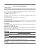


HOW TO READ DESCRIPTIONS
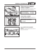
1. A disassembly/installation job instruction mainly consists of the exploded diagram
11
.
2. The numerical figures represented by the number
22
indicates the order of the job steps.
3. The symbols represented by the number
33
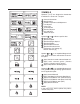
indicates the contents and notes of the job.
For the meanings of the symbols, refer to the next page(s).
4. The REMOVAL AND INSTALLATION CHART
44
is attached to the exploded diagram and
explains the job steps, part names, notes for the jobs, etc.
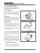
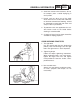
5. The SERVICE POINTS, other than the exploded diagram, explains in detail the items difficult to
explain in the exploded diagram of REMOVAL AND INSTALLATION CHART, the Service Points
requiring the detailed description
55
, etc.