U Integrated Amplifier Amplificateur Intégré OWNER’S MANUAL MODE D’EMPLOI
IMPORTANT SAFETY INSTRUCTIONS IMPORTANT SAFETY INSTRUCTIONS CAUTION RISK OF ELECTRIC SHOCK DO NOT OPEN CAUTION: TO REDUCE THE RISK OF ELECTRIC SHOCK, DO NOT REMOVE COVER (OR BACK). NO USER-SERVICEABLE PARTS INSIDE. REFER SERVICING TO QUALIFIED SERVICE PERSONNEL.
IMPORTANT SAFETY INSTRUCTIONS FCC INFORMATION (for US customers) 1 IMPORTANT NOTICE: DO NOT MODIFY THIS UNIT! This product, when installed as indicated in the instructions contained in this manual, meets FCC requirements. Modifications not expressly approved by Yamaha may void your authority, granted by the FCC, to use the product. 2 IMPORTANT: When connecting this product to accessories and/or another product use only high quality shielded cables. Cable/s supplied with this product MUST be used.
CAUTION: READ THIS BEFORE OPERATING YOUR UNIT. CAUTION: READ THIS BEFORE OPERATING YOUR UNIT. 1 2 3 4 5 6 7 8 9 10 11 12 13 14 15 16 To assure the finest performance, please read this manual carefully. Keep it in a safe place for future reference. Install this sound system in a well ventilated, cool, dry, clean place - away from direct sunlight, heat sources, vibration, dust, moisture, and/or cold. For proper ventilation, allow the following minimum clearances around this unit.
CONTENTS Front panel ........................................................2 Rear panel .........................................................4 Remote control..................................................6 PLAYBACK................................................. 11 Playing a source ............................................. 11 Adjusting to the desired sound ....................... 12 TROUBLESHOOTING.............................. 13 SPECIFICATIONS .....................................
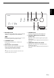
CONTROLS AND FUNCTIONS Front panel (A-S701) 1 A (power) switch Turns on and off the power of this unit. 4 PHONES jack Connect your headphones. Note 5 SPEAKERS selector Even when this unit is turned off, this unit consumes a small amount of power. 2 Power indicator Indicator Status Brightly lit The power of this unit is “on”. Dimly lit This unit is in “standby” mode. For details on the “standby” mode, see page 6. Off The power of this unit is “off”.
CONTROLS AND FUNCTIONS English (A-S701) 8 BALANCE control Adjusts the sound output balance of the left and right speakers to compensate for sound imbalances. Note If you rotate the BALANCE control to the end of L (left) or R (right), the opposite side of channel is muted. 9 LOUDNESS control Retain a full tonal range at any volume level (see page 12). 0 INPUT selector and indicators Selects the input source you want to listen to.
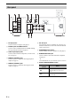
CONTROLS AND FUNCTIONS Rear panel (A-S501/S301) (A-S701) 1 CD input jacks Used to connect a CD player (see page 9). 2 PHONO jacks and GND terminal Used to connect a turntable that uses an MM cartridge, and to ground the terminal (see page 9). 3 Audio input/output jacks Used to connect external components, such as a tuner, etc (see page 9). 4 DIGITAL (OPTICAL) jack Used to connect a component with a digital optical output (see page 9).
CONTROLS AND FUNCTIONS (A-S501/S301) English (A-S701) 0 VOLTAGE SELECTOR (General model only) Used to set to your local main voltage (see page 10). A IMPEDANCE SELECTOR switch CAUTION Do not change the IMPEDANCE SELECTOR switch while the power is turned on, as doing so may damage the unit. If the IMPEDANCE SELECTOR switch may not be fully slid to either position, remove the power cable and slide the switch all the way to either position.
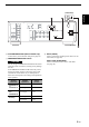
CONTROLS AND FUNCTIONS Remote control (A-S701) 1 Infrared signal transmitter Sends infrared signals. 2 A AMP Turns this unit on, or sets it to standby mode. 3 OPEN/CLOSE Opens/closes the disc tray of the Yamaha CD player. Refer to the owner’s manual of your CD player for details. Note Even when using a Yamaha CD player, certain components and features may not be available. (A-S501/S301) 4 A CD Turns the Yamaha CD player on, or sets it to standby mode.
CONTROLS AND FUNCTIONS 7 VOLUME +/– Increases or decreases the sound output level. 9 PURE DIRECT Reproduces any input source in the purest sound possible (see page 12). 0 Yamaha tuner control buttons The following buttons can be used to control various functions of a Yamaha tuner. Refer to your component’s owner’s manual for more information.
CONTROLS AND FUNCTIONS ■ Installing batteries AA, R6, UM-3 batteries ■ Operation range Point the remote control at the remote control sensor on this unit and remain within the operating range shown below. Approximately 6m (20 ft) Remote control ■ • • • • • • • • • • • • Notes on remote control and batteries The area between the remote control and this unit must be clear of large obstacles. Be careful not to spill water or other liquids on the remote control.
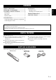
CONNECTIONS Make sure to connect L (left) to L, R (right) to R, “+” to “+” and “–” to “–”. If the connections are faulty, no sound will be heard from the speakers, and if the polarity of the speaker connections is incorrect, the sound will be unnatural and lack bass. Refer to the owner’s manual for each of your components. Make sure to use RCA cables or optical cable to connect audio components.
CONNECTIONS ■ REC jacks Rear panel • The audio signals are not output via the LINE 2 REC or LINE 3 REC output jacks when LINE 2 or LINE 3 is selected with the INPUT selector. • The VOLUME, BASS, TREBLE, BALANCE and LOUDNESS controls and the CD DIRECT function (or the PURE DIRECT function) have no effect on the source being recorded. Speaker ■ Connecting speaker cables 1 Remove approximately 10 mm (3/8 in) of insulation from the end of each speaker cable.
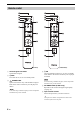
PLAYBACK SPEAKERS 4 VOLUME Rotate the SPEAKERS selector on the front panel to select SPEAKERS A, B or A+B BIWIRING. y Set the SPEAKERS selector to the A+B BI-WIRING position when two sets of speakers are connected using bi-wire connections, or when using two sets of speakers simultaneously (A and B). (A-S701) A 5 Play the selected input source. 6 Rotate the VOLUME control on the front panel (or press VOLUME +/– on the remote control) to adjust the sound output level.
PLAYBACK Adjusting to the desired sound LOUDNESS VOLUME ■ Reproducing pure, high fidelity sound (PURE DIRECT) When the PURE DIRECT function is on, noise can be reduced by bypassing the circuit that the audio input signal is not using and stopping the power supply to the circuit. Therefore, in all input sources, you can enjoy music playback in straight and high quality sound. The indicator above the PURE DIRECT button lights up when this function is turned on.
TROUBLESHOOTING Problem This unit fails to turn on. This unit turns off suddenly and the power indicator blinks. Cause See page The power cable is not connected or the plug is not completely inserted. Connect the power cable firmly. The A AMP is pressed on the remote control while this unit is turned off. Press A (power) switch on the front panel to on. The impedance setting of the connected speaker is too small. Use speaker(s) with proper speaker impedance.
TROUBLESHOOTING Problem Cause Remedy See page Playback has been stopped on the connected component. Turn the component on and start playback. No appropriate input source has been selected. Select an appropriate input source with the INPUT selector on the front panel (or one of the Input selector buttons on the remote control). 11 The SPEAKERS selector is not set properly. Set the corresponding SPEAKERS selector to A, B or A+B BI-WIRING position.
SPECIFICATIONS AUDIO SECTION Minimum RMS output power A-S701 A-S501 A-S301 8 Ω, 20 Hz to 20 kHz, 0.019% THD 100 W + 100 W 85 W + 85 W 60 W + 60 W 6 Ω, 20 Hz to 20 kHz, 0.038% THD (Except for Asia and China models) 120 W + 120 W 100 W + 100 W 70 W + 70 W 8Ω 140 W 130 W 100 W 6Ω 170 W 150 W 120 W 4Ω 220 W 185 W 140 W 2Ω 290 W 220 W 150 W Maximum power per channel 1 kHz, 0.7% THD, 4 Ω (U.K. and Europe models only) 160 W 120 W 95 W IEC power 1 kHz, 0.019% THD, 8 Ω (U.K.
SPECIFICATIONS Item Signal to noise ratio (IHF-A network) A-S701 A-S501 PHONO (MM) (5 mV input shorted) 82 dB or more CD, etc. PURE DIRECT on (200 mV input shorted) 99 dB or more CD DIRECT AMP on 104 dB or more Residual noise (IHF-A network) Channel separation A-S301 — — 40 μV CD, etc. (5.1 kΩ input shorted, 1 kHz) 65 dB or more CD, etc. (5.
PRÉCAUTIONS CONCERNANT LA SÉCURITÉ PRÉCAUTIONS CONCERNANT LA SÉCURITÉ CAUTION RISK OF ELECTRIC SHOCK DO NOT OPEN ATTENTION : POUR RÉDUIRE LES RISQUES D’INCENDIE ET DE DÉCHARGE ELECTRIQUE, NE PAS RETIRER LE COUVERCLE (OU LE PANNEAU ARRIÈRE). AUCUNE PIÈCE INTERNE NE PEUT ÊTRE CHANGÉE PAR L’UTILISATEUR. POUR L’ENTRETIEN, S’ADRESSER À UN PERSONNEL QUALIFIÉ.
PRÉCAUTIONS CONCERNANT LA SÉCURITÉ Informations de la FCC (Pour les clients résidents aux États-Unis) 1 AVIS IMPORTANT : NE PAS APPORTER DE MOFIDICATIONS À CET APPAREIL ! Ce produit est conforme aux exigences de la FCC s’il est installé selon les instructions du mode d’emploi. Toute modification non approuvée expressément par Yamaha peut invalider l’autorisation, accordée par la FCC, d’utiliser ce produit.
ATTENTION : VEUILLEZ LIRE CE QUI SUIT AVANT D’UTILISER L’APPAREIL. ATTENTION : VEUILLEZ LIRE CE QUI SUIT AVANT D’UTILISER L’APPAREIL. 1 Pour utiliser l’appareil au mieux de ses possibilités, lisez attentivement ce mode d’emploi. Conservez-le soigneusement pour référence. 2 Installez cet ensemble audio dans un endroit bien aéré, frais, sec et propre - veillez à ce qu’il soit à l’abri de la lumière directe du soleil, des sources de chaleur, des vibrations, des poussières, de l’humidité et/ou du froid.
TABLE DES MATIÈRES FONCTIONS UTILES .................................. 1 ACCESSOIRES FOURNIS .......................... 1 COMMANDES ET FONCTIONS ............... 2 Panneau avant ...................................................2 Panneau arrière .................................................4 Télécommande..................................................6 LECTURE.................................................... 11 Lecture d’une source ......................................
COMMANDES ET FONCTIONS Panneau avant (A-S701) 1 Commutateur A (alimentation) Met cet appareil sous et hors tension. 4 Prise PHONES Pour brancher votre casque. 5 Sélecteur SPEAKERS Remarque Cet appareil consomme une petite quantité d’énergie même lorsqu’il est hors tension. Position du sélecteur 2 Témoin d’alimentation OFF Les deux jeux d’enceintes sont hors tension. Cet appareil est « sous tension ». A ou B Le jeu d’enceintes branché aux bornes A ou B est sous tension.
COMMANDES ET FONCTIONS Français (A-S701) 8 Commande BALANCE Équilibre le son reproduit par les enceintes gauche et droite afin de compenser le déséquilibre sonore. Remarque Si vous tournez la commande BALANCE jusqu’à l’extrémité de L (gauche) ou R (droite), le son du côté opposé du canal est désactivé. 9 Commande LOUDNESS Conserve une plage de tonalités complète à n’importe quel niveau de volume (voir page 12). 0 Sélecteur et témoins INPUT Sélectionne la source d’entrée que vous souhaitez écouter.
COMMANDES ET FONCTIONS Panneau arrière (A-S501/S301) (A-S701) 1 Prises d’entrée CD Pour brancher un lecteur de CD (voir page 9). 2 Prises PHONO et borne GND Pour raccorder un tourne-disque utilisant une cartouche MM et pour mettre la borne à la terre (voir page 9). 3 Prises d’entrée/de sortie audio Pour raccorder des périphériques externes, tels qu’un syntoniseur, etc. (voir page 9). 4 Prise DIGITAL (OPTICAL) Pour raccorder un composant doté d’une sortie optique numérique (voir page 9).
COMMANDES ET FONCTIONS (A-S501/S301) Français (A-S701) 0 VOLTAGE SELECTOR (Pour le modèle général uniquement) Pour régler votre tension secteur locale (voir page 10). A Commutateur IMPEDANCE SELECTOR ATTENTION Ne modifiez pas le commutateur IMPEDANCE SELECTOR lorsque cet appareil est sous tension, car vous risqueriez de l’endommager.
COMMANDES ET FONCTIONS Télécommande (A-S701) 1 Émetteur de signal infrarouge Envoie des signaux infrarouges. 2 A AMP Met cet appareil sous tension ou en mode veille. 3 OPEN/CLOSE Ouvre/ferme le plateau de disque du lecteur de CD Yamaha. Pour plus de détails, reportez-vous au mode d’emploi de votre lecteur de CD. Remarque Même si vous utilisez un lecteur de CD Yamaha, il se peut que certains composants et certaines fonctions ne soient pas disponibles.
COMMANDES ET FONCTIONS 7 VOLUME +/– Augmente ou réduit le niveau sonore en sortie. 9 PURE DIRECT Reproduit toute source d’entrée avec le son le plus pur possible (voir page 12). 0 Touches de commande d’un syntoniseur Yamaha Vous pouvez utiliser les touches suivantes pour commander les différentes fonctions d’un syntoniseur Yamaha. Pour plus d’informations, reportez-vous au mode d’emploi des composants.
COMMANDES ET FONCTIONS ■ Installation des piles Piles AA, R6, UM-3 ■ Portée de la télécommande Dirigez la télécommande vers le capteur de télécommande de cet appareil et restez dans la zone de portée de la télécommande indiquée ci-dessous. Environ 6m Télécommande ■ • • • • • • • • • • • • Remarques sur la télécommande et les piles Entre la télécommande et cet appareil, l’espace doit être libre d’obstacle. Faites attention à ne pas renverser d’eau ou d’autres liquides sur la télécommande.
RACCORDEMENTS Raccordement des enceintes et des composants sources Assurez-vous de raccorder L (gauche) sur L, R (droite) sur R, « + » sur « + » et « – » sur « – ». Si le raccordement est défectueux, aucun son n’est émis par l’enceinte, et si la polarité de la connexion est incorrecte, les sons manquent de naturel et de composantes graves. Reportez-vous au mode d’emploi de chaque composant. Assurez-vous d’utiliser les câbles RCA ou un câble optique pour raccorder les composants audio.
RACCORDEMENTS ■ Prises REC Panneau arrière • Les signaux audio ne sont pas émis par les prises de sortie LINE 2 REC ou LINE 3 REC lorsque LINE 2 ou LINE 3 est sélectionné avec le sélecteur INPUT. • Les commandes VOLUME, BASS, TREBLE, BALANCE et LOUDNESS et la fonction CD DIRECT (ou la fonction PURE DIRECT) n’ont aucun effet sur la source enregistrée. Enceinte ■ Raccordement des câbles d’enceinte 1 Retirez environ 10 mm d’isolation à l’extrémité de chaque câble d’enceinte.
LECTURE Lecture d’une source SPEAKERS 4 VOLUME Tournez le sélecteur SPEAKERS du panneau avant afin de sélectionner SPEAKERS A, B ou A+B BI-WIRING. y (A-S701) A 5 Lisez la source d’entrée sélectionnée. 6 Tournez la commande VOLUME du panneau avant (ou appuyez sur les touches VOLUME +/– de la télécommande) pour régler le niveau sonore en sortie.
LECTURE Réglage du son de votre choix LOUDNESS VOLUME (A-S701) CD DIRECT AMP PURE DIRECT ■ Écoute simplifiée des aigus et des graves même à faible volume (LOUDNESS) Profitez d’un son naturel même à faible volume en abaissant le niveau sonore des sons médium et en compensant la perte de sensibilité des oreilles humaines aux aigus et aux graves à faible volume.
GUIDE DE DÉPANNAGE Reportez-vous au tableau suivant si cet appareil ne fonctionne pas comme il devrait. Si le problème que vous rencontrez n’est pas mentionné ci-dessous, ou encore si les actions correctives suggérées sont sans effet, mettez cet appareil hors tension, débranchez le câble d’alimentation et prenez contact avec le revendeur ou le service après-vente agréé Yamaha le plus proche. Impossible de mettre cet appareil sous tension.
GUIDE DE DÉPANNAGE Anomalies Causes possibles Actions correctives Voir page La lecture a été interrompue sur le composant connecté. Mettez le composant sous tension et lancez la lecture. Aucune source d’entrée appropriée n’est sélectionnée. Sélectionnez une source d’entrée appropriée à l’aide du sélecteur INPUT du panneau avant (ou de l’une des touches du sélecteur d’entrée de la télécommande). 11 Le sélecteur SPEAKERS n’est pas correctement réglé.
SPÉCIFICATIONS SECTION AUDIO Élément A-S501 A-S301 100 W + 100 W 85 W + 85 W 60 W + 60 W Puissance minimale de sortie efficace (RMS) 6 Ω, 20 Hz à 20 kHz, 0,038 % THD (Sauf modèles pour l’Asie et la Chine) 120 W + 120 W 100 W + 100 W 70 W + 70 W 8Ω 140 W 130 W 100 W Puissance dynamique par canal (IHF) 6Ω 170 W 150 W 120 W 4Ω 220 W 185 W 140 W 2Ω 290 W 220 W 150 W Puissance maximale par canal 1 kHz, 0,7 % THD, 4 Ω (Modèles pour le Royaume-Uni et l’Europe uniquement) 160 W 120 W
SPÉCIFICATIONS Élément A-S701 A-S501 PHONO (MM) (5 mV entrée court-circuitée) 82 dB ou plus Rapport signal/bruit (réseau IHF-A) CD, etc. PURE DIRECT active (200 mV entrée court-circuitée) CD DIRECT AMP active A-S301 99 dB ou plus 104 dB ou plus Bruit résiduel (réseau IHF-A) — — 40 μV Séparation de canaux CD, etc. (5,1 kΩ entrée courtcircuitée, 1 kHz) 65 dB ou plus CD, etc.