
Service manual


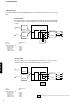
Table Of Contents
- TO SERVICE PERSONNEL
- FRONT/REAR PANELS
- SPECIFICATIONS
- AV-S70 DISASSEMBLY PROCEDURES
- SW-AVS70 DISASSEMBLY PROCEDURES
- TEST PROGRAM MODE
- DSP DIAG MODE
- AV-S70 IC DATA
- AV-S70 BLOCK DIAGRAM
- SW-AVS70 BLOCK DIAGRAM
- AV-S70 PRINTED CIRCUIT BOARD
- SW-AVS70 PRINTED CIRCUIT BOARD
- AV-S70 SCHEMATIC DIAGRAM
- SW-AVS70 SCHEMATIC DIAGRAM
- PARTS LIST
- REMOTE CONTROL TRANSMITTER
- Parts List for Carbon Resistors
AV-S70/NX-SW70
AV-S70/NX-SW70
5
■ TEST PROGRAM MODE (AV-S70)
1. Procedure for starting Test Program
With the power turned off, press the POWER key while pressing the VOLUME key and the DSP key simultaneously. This
initiates the Test Program function.
When the Test Program is initiated, “01 DEST-Ex” appears on the FL display.
2. Procedure for selecting and executing Test Program
Using the VOLUME + (UP) key and Volume - (DOWN) key, select the Test Program and then press the INPUT key to execute
it.
3. Procedure for canceling Test Program
There are two methods for cancellation.
a. Turn off the power by pressing the POWER key of the main unit or the remote controller.
b. Select the Test Program “01 DEST-Ex” and press the INPUT key for execution. (The normal mode will be restored.)
4. Details of the Test Program function
Display
01 DEST-B,G1
Function
Destination display/ test program end
Destination display
J:Ja J (Japanese)
J:En J (English)
B,G1 B, G models
02 FL+CLEAR
FL display segments all light up / BACKUP RAM CLEAR
1
st
time: FL display segments all light up and standby LED lights up.
2
nd
time: RAM CLEAR is executed (RAM CLEAR OK on display)
* State before shipped out of the factory preset.
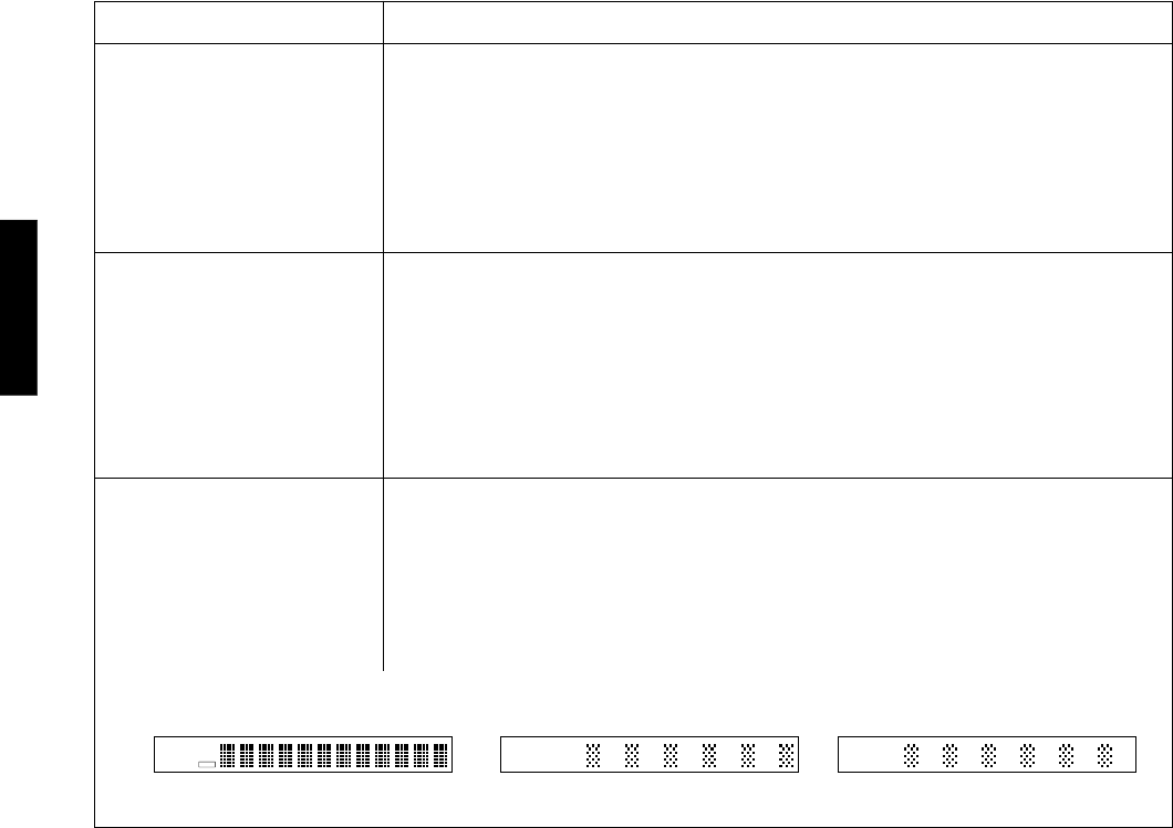
03 FL CHECK
FL display light-up check
1
st
time: FL display segments all light up and standby LED lights up.
2
nd
time: Even number segments and digits light up.
3
rd
time: Odd number segments and digits light up.
1
st
time 2
nd
time 3
rd
time
DSP
V
DIGITAL ENHANCED
V
SURROUND
V
PRO LOGIC
VIRTUAL TRUBASS
V
ENHANCED
SURROUND
PRO LOGIC
TRUBASS