PROFESSIONAL AUDIO WORKSTATION Owner’s Manual Keep This Manual For Future Reference.
FCC INFORMATION (U.S.A.) 1. IMPORTANT NOTICE: DO NOT MODIFY THIS UNIT! This product, when installed as indicated in the instructions contained in this manual, meets FCC requirements. Modifications not expressly approved by Yamaha may void your authority, granted by the FCC, to use the product. 2. IMPORTANT: When connecting this product to accessories and/or another product use only high quality shielded cables. Cable/s supplied with this product MUST be used. Follow all installation instructions.
NEDERLAND THE NETHERLANDS ● Dit apparaat bevat een lithium batterij voor geheugen back-up. ● This apparatus contains a lithium battery for memory back-up. ● Raadpleeg uw leverancier over de verwijdering van de batterij op het moment dat u het apparaat ann het einde van de levensduur afdankt of de volgende Yamaha Service Afdeiing: Yamaha Music Nederland Service Afdeiing Kanaalweg 18-G, 3526 KL UTRECHT Tel.
Important Important Read the following before operating the AW2816 • If lightning begins to occur, turn off the power switch of the unit as soon as possible, and unplug the power cable plug from the electrical outlet. ■ Warnings • If there is a possibility of lightning, do not touch the power cable plug if it is still connected. Doing so may be an electrical shock hazard. • Do not place a container with liquid or small metal objects on top of this unit.
Handling the CD-R/RW media Please observe the following points when handling the disk. Failure to do so may cause problems such as the recorded data being lost, the drive to malfunction, or the printed label to become blurred. • Do not place the disk in locations of direct sunlight, high temperature, or high humidity. • Do not touch either surface of the disk. • Hold the disk at the edges. Gently wipe dust or dirt off of the recording surface of the disk.
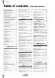
Table of contents Table of contents —Operation section— Before you begin .....................1 Checking the included items ...................1 Installing an internal hard disk ................2 About the internal hard disk..........................2 Installation ....................................................2 Installing a CD-RW drive.........................4 About the CD-RW drives ..............................4 CD-RW drive settings ...................................4 Installation procedure ....
Editing the name of a scene ................ 130 Protecting a scene............................... 131 Changing the order of scenes ............. 132 Setting the mastering mode ................ 181 Executing mastering............................ 182 Finalizing a disc .................................. 185 Chapter9 Using automix .........133 Chapter13 MIDI....................... 187 About automix .................................... 133 What you can do using MIDI..............
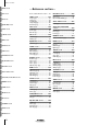
Table of contents SONG screen —Reference section— FILE screen How to read the Reference section .... 236 SONG screen ........................237 CD screen QUICK REC screen Song List page ..................................... 237 Setting page......................................... 238 Song Edit page..................................... 240 Tempo Map page ................................ 241 Shut Down page.................................. 243 FILE screen...........................
Appendix —Appendix— Preset EQ Program Parameters........... 356 Preset Effects Programs....................... 360 Effects Parameters............................... 362 Dynamics Processors .......................... 377 Preset Dynamics Programs .......................377 Index Preset Dynamics Program Parameters 382 Troubleshooting.................................. 388 Display message list ............................ 392 Messages ..................................................392 Popup messages ......
Before you begin Before you begin This chapter explains preparations you need to make before using the AW2816, such as checking the included items and installing options. Checking the included items Please make sure that the package contains the following items. If any items are missing, please contact your dealer.
Before you begin Installing an internal hard disk You must install a hard disk in the AW2816 before using it. If you attempt to use the AW2816 without installing a hard disk, the recorder section and mixer section will fail to operate correctly, and the AW2816 will be damaged as well. About the internal hard disk On the AW2816, all data necessary for reproducing a composition (mixer settings, recorder settings, audio data etc.) is stored on the hard disk as a “song.
Spread a soft cloth over your work surface, and place magazines or books to support the four corners of the AW2816 so that the faders, keys, and other controllers on the top panel will not be damaged. Then turn the AW2816 face down. 4 From the bottom, unfasten the hard disk cover plate to which the internal 2.5 inch IDE hard disk will be attached. • Even if the connector is difficult to insert, do not attempt to insert it by applying excessive force.
Before you begin Installing a CD-RW drive About the CD-RW drives CD-RW drive settings A CD-RW drive is an option that allows you to create music CD’s, to backup/restore internal hard disk data, to play a music CD or to read a CD-ROM. An internal-type CD-RW drive can be installed by removing the CD-RW drive cover from the front panel. CD-RW drives with the following specifications can be used.
Installation procedure Turn the CD-RW drive over, and insert it little by little, stopping when the connector end of the CD-RW drive enters the opening in the bottom of the AW2816. 6 Connect the flat cable (1) and CD-RW drive power supply connector (2) (from inside the AW2816) to the connectors of the CD-RW drive. Connect the flat cable first, and then the power supply connector. Please carefully read the cautions for installing optional equipment given at the beginning of this manual.
Before you begin 7 Align the fastening screw-holes on the bottom of the CD-RW drive with the screwholes in the AW2816, and using a screwdriver and the included screws, fasten it in four locations. 8 Re-attach the CD-RW drive cover and the bottom panel that you removed in step 4. At this time, remove the inner cover from the CD-RW drive cover.
Removing the transport protection pad Before you begin The disc tray of some CD-RW drive models contains a transport protection pad that protects the internal mechanism from physical shock suffered during shipment. If your CD-RW drive contains this protective pad, please remove it before use. Be sure to save the transport protection pad for the next time you need to transport the unit.
Before you begin Attaching an external SCSI device About external SCSI devices Connection procedure The external SCSI devices referred to here are storage devices used to backup/restore the internal data of the AW2816, and can be connected to the SCSI connector on the rear panel of the AW2816. The following types of storage device can be used. 1 Make sure that the power is turned off for the AW2816 and for the external SCSI device(s), and use a SCSI cable to connect the SCSI connectors of each device.
2 Attach a terminator to the last SCSI device in the chain. Before using an external SCSI device, you will need to format it. For details on this procedure, refer to page 160. ■ About terminators Before you begin A “terminator” is a device that terminates the SCSI signal at the end of the chain, and is normally attached to the vacant SCSI connector of the last device in the daisy chain. If the SCSI device itself has a built-in terminator, turn it on.
Before you begin Installing I/O card 2 About I/O cards I/O cards compatible with the Yamaha mini-YGDAI format can be installed in the OPTION I/O slot located on the rear panel of the AW2816 in order to add input/output ports. For example by installing an ADAT format compatible I/O card into an OPTION I/ O slot, you can transmit/receive eight channels of digital audio to/from an ADAT format digital recorder.
Please observe the following points Before you begin This section explains how to turn the power of the AW2816 on and off, and how to set the internal clock. Turning the power on Setting the internal clock When turning on the power of a system that includes the AW2816, each device must be turned on in the following order. When the AW2816 is shipped from the factory, the internal clock is set to Japan time.
Before you begin Turning the power off When turning off the power of a system that includes the AW2816, each device must be turned off in the following order. 1 The monitor system connected to the output jacks or the AW2816 B The AW2816 itself C Any storage devices connected to the SCSI connector of the AW2816, and external tone generators connected to the input/output jacks When turning off the power of the AW2816 itself, you must use the shutdown procedure described below.
Chapter 1 Parts and their functions This chapter explains the functions of each part of the AW2816’s top panel, rear panel, and front panel. 1 Parts and their functions The names of controllers (keys and knobs etc.) on the top panel are enclosed in square brackets [ ] in order to distinguish them from the software knobs and buttons that appear in the display.
Chapter Parts and their functions 1 WORK NAVIGATE section MIXER section EQ/ATT/GRP EQ/ATT/GRP 1 2 3 4 1 A [SONG] key B [FILE] key C [CD] key This key accesses the CD screen, where you can use an optional CD-RW drive to create an audio CD, or play back an audio CD. D [QUICK REC] (Quick Record) key This key accesses the VIEW screen, where you can view all mix parameters for a specified channel.
FADER MODE section MIXING LAYER section 1 1 2 3 4 2 Parts and their functions 1 3 A INPUT [1-8] key B RECORDER [1-8] key This section selects the parameters that will be controlled by the top panel faders 1–8. The selected key will light. A [HOME] key When this key is on, you can use faders 1–8 to control the input levels of the channels currently selected in the MIXING LAYER section.
Chapter Parts and their functions 1 Fader section 1 2 4 3 A [SEL] keys (1–8/STEREO/RTN 1/RTN 2) These keys select the channel for operation. B [ON] keys (1–8/STEREO/RTN 1/RTN 2) These keys turn each channel on/off. C Faders (1–8/STEREO) According to the settings of the FADER MODE section and MIXING LAYER section, these moving faders adjust either the input level of each channel or the send level of each channel to AUX buses 1– 6.
Display section 1 Parts and their functions 6 1 5 2 3 4 A Display D [CTRL] (Control) key This is a 320 x 240 pixel liquid crystal display with backlight, that displays the mix parameter settings and the current operating status. When you press one of the keys in the WORK NAVIGATE or UNIT section, the screen for the corresponding key will appear.
Chapter Parts and their functions 1 REC TRACK SELECT section RECORDER section 1 2 1 3 2 3 4 4 A [TRACK] key A [CUE] key This key allows the output of tracks 1–16 or the stereo track to be monitored directly from the MONITOR OUT jacks without passing through the monitor channel. Use the REC TRACK SELECT keys (3) to select a track. When you press the [CUE] key, the [CUE] key and the REC TRACK SELECT keys will blink, allowing you to select a track.
AUTOMATION section CURSOR/JOG&SHUTTLE section 1 2 Parts and their functions 1 1 A [AUTOMIX] key 3 2 This key accesses the AUTOMIX screen, where you can perform automix operations. By using automix, operations of mix parameters such as the faders and [ON] keys can be recorded in realtime. B [SCENE] key This key accesses the SCENE screen, where you can perform scene memory operations. By using scene memories, you can save the current state of the mixer section and the input/output patching state.
Chapter Parts and their functions 1 G [REPEAT] key LOCATE section This key is an on/off switch for the A-B Repeat function which repeatedly plays a specified region. H [A]/[B] keys These keys set the beginning (A point) and end (B point) of the region played by the A-B Repeat function. These keys can also be used as locate keys to specify the A point or B point as locate destinations. 1 2 3 I [ROLL BACK] key This key rewinds the current location by a specified distance.
Transport section 1 A REW [ 2 3 4 Parts and their functions 1 5 ] (Rewind) key This key rewinds from the current location. Each time you press this key, you will switch between 8X speed and 16X speed rewinding. To stop rewinding, press the STOP [ ] key or PLAY [ ] key. B FF [ ] (Fast-forward) key This key fast-forwards from the current location. Each time you press this key, you will switch between 8X speed and 16X speed fast-forwarding.
Chapter Parts and their functions 1 Rear panel N U T M L K J SRQ P 5 O 3 2 1 4 9 8 7 6 A [PHANTOM +48V ON/OFF] switch This switch supplies +48 V phantom power to the INPUT (XLR) 1/2 jacks (2). Turn this switch ON when condenser mics that require an external power supply are connected to the INPUT 1/2 (XLR) jacks. • If plugs are inserted into both the XLR jack and TRS phone jack of INPUT 1/2, the TRS phone jack will take priority.
I OMNI OUT jacks These unbalanced phone jacks are analog outputs for the signals selected in the PATCH screen Patch OUT page (→P.284). The nominal output level is 0 dB. J PHONES jack K DIGITAL STEREO IN jack This is a coaxial jack for digital input of a stereo signal. It supports the IEC 958 consumer format. L DIGITAL STEREO OUT jack This is a coaxial jack for digital output of the signal selected in the PATCH screen Patch OUT page (→P.284). It supports the IEC 958 consumer format.
Chapter Parts and their functions 1 Front panel 1 A CD-RW drive cover This covers the installation bay for the optional CD-RW drive. Tip! For details on installing a CD-RW drive, refer to page 4.
Chapter 2 Welcome to the world of the AW2816 This chapter explains the features and signal flow of the AW2816, and covers basic operation. 2 The AW2816 is an audio workstation that combines a digital mixer, hard disk recorder, and multi-effect unit. It allows you to carry out the entire music production process — multi-track recording, mixing, audio editing, effect processing, and CD production (*1) — without needing any other equipment. This section explains the features of each section of the AW2816.
Chapter Welcome to the world of the AW2816 2 CD-RW drive (option) • CD-RW drive can be installed internally Stereo tracks on the hard disk can be used to produce an audio CD off-line. The CD-RW drive can also be used to store recorded data for backup. Playback of audio CD’s and loading from CD-ROM is also supported. Other features • Simple panel layout and efficient operation A large backlit LCD screen provides excellent visibility.
Signal flow within the AW2816 The following diagram shows the general signal flow within the AW2816. As you can see from this diagram, the AW2816 is divided into input patch, output patch, mixer, recorder, and CD-RW drive (option) sections.
Chapter Welcome to the world of the AW2816 2 MIC/LINE INPUT PHANTOM +48V PEAK INPUT 1-2 AD INPUT1-24 LINE MIC PEAK INPUT 3-8 INPUT PATCH AD LINE MIC Hi-z INPUT 8 ONLY OPTION I/O SLOT 8 SLOT IN INPUT1-24 2 EFFECT1 EFFECT2 2 DIGITAL STEREO IN 2 COAXIAL METRONOME Input channels 1–8 INPUT SELECT METER INSERT ON LEVEL ATT DYNAMICS 4BAND EQ METER (EQ) PAN INPUT DELAY METER (Gain Reduction) Mono in X 8 28 METER METER PREFADER LISTEN/ AFTER PAN SOLO PRE/POST ON AUX CH DIRECT OUT
Return channels 1/2 Recorder input patch These are stereo input channels used mainly for inputting the return signal from internal effects 1/2. However, the input signal assignment can be changed in the input patch section, allowing these to be used as additional input channels. This section assigns input signals to the tracks of the recorder. The following signals can be selected for tracks 1–16. • BUS 1–8 The output signals of buses 1–8.
Chapter Welcome to the world of the AW2816 2 Monitor channels 1–16 These are monaural channels assigned to the output of tracks 1–16 of the recorder section. Depending on the input monitor setting and the state of the transport, these will input either the signals that are currently being input to tracks 1–16 or the playback signals of tracks 1–16.
Stereo output channel This is a stereo output channel that processes the signals sent from each channel to the stereo bus. It provides a 4-band EQ and dynamics processor identical to those provided on the input channels. The output signal of the stereo output channel is sent via the output patch section to the various output jacks, and is also simultaneously output to the MONITOR OUT jacks and PHONES jack.
Chapter Welcome to the world of the AW2816 2 Output patch Internal effects 1/2 This section assigns output signals to OMNI OUT jacks 1–4, the STEREO OUT jacks, DIGITAL STEREO OUT jack, and an I/O card installed in the OPTION I/ O slot. The following output signals can be selected. With the AW2816’s default settings, the outputs of AUX buses 5/6 are patched to the inputs of internal effects 1/2 respectively. Also, the outputs of effects 1/2 are assigned to return channels 1/2.
The track structure of the AW2816 This section explains the track structure of the AW2816. The recorder section of the AW2816 handles three types of tracks: audio tracks, virtual tracks, and the stereo track. Audio tracks The following tables show the number of tracks that can be simultaneously recorded and simultaneously played back, and the number of tracks that will be muted in each case, for 16 bit and 24 bit songs.
Chapter Welcome to the world of the AW2816 2 About the display This section explains what you will see in the LCD display of the top panel. The display shows the following information. 3 45 6 7 1 2 8 A Screen name F Level meters L/R This is the name of the currently selected screen. B Page name/channel The information appearing here will depend on the screen, and will be either the name of the page selected within that screen, or the channel that is selected for operation.
Buttons Buttons in the display are used to switch a parameter on/off, or to select one of multiple choices. Currentlyon buttons are highlighted as white text on a black background, and currently-off buttons are displayed as black text on a white background. 2 Off On Welcome to the world of the AW2816 Knobs/faders/numerical boxes Knobs/faders/numerical boxes in the display are used to edit the value of the corresponding parameter. The value of a knob or fader is displayed below or at the right of it.
Chapter Welcome to the world of the AW2816 2 Basic operation of the AW2816 This section explains basic operations of the AW2816, such as screen operations and selecting channels. Tip! Accessing screens and pages • You can also move successively between the pages of a screen by repeatedly pressing the same key in step 1. • In this manual, consecutive key operations are listed as “[PATCH] key → [F2] key” (press the [PATCH] key and then press the [F2] key).
Using the additional function buttons 1 When a symbol is shown in the lower left of the display, you can press and hold the [SHIFT] key to access new buttons in the bottom of the display, and use various additional functions. 1 4 3 2 5 In a screen that displays a symbol in the lower left, press and hold the [SHIFT] key. 2 1 2 Continue to hold the [SHIFT] key, and press the function key ([F1]–[F5] key) corresponding to the desired button.
Chapter Welcome to the world of the AW2816 2 2 Use the [CURSOR] keys to move the cursor within the character palette to the button for the character you want to input, and press the [ENTER] key. The corresponding character/symbol/numeral will be input, and the highlighted area in the text input box will move to the right. 3 Selecting a channel In order to operate the mix parameters of a channel on the AW2816, you must first select the channel that you want to operate. Here’s how to select a channel.
The following table shows how the parameters controlled by faders 1–8 will change depending on the fader mode.
Chapter 3 Let’s record on the AW2816 As a way to explain the basic operations of multi-track recording and mixdown on the AW2816, this chapter describes how you can successively record instruments such as rhythm machine (drums), bass, guitar, and keyboard to create a song. You will also learn more advanced techniques that you will find convenient.
Chapter Let’s record on the AW2816 3 • Connect line-level instruments (rhythm machines and synthesizers) to the INPUT 1–8 (phone) jacks. • If you use mics, connect them to the INPUT 1–8 (phone) jacks or the INPUT 1/2 (XLR) jacks. • If you use condenser mics that require phantom power, connect them to the INPUT 1/2 (XLR) jacks, and turn the rear panel [PHANTOM +48V ON/OFF] switch on.
5 Use the Fs and Recbit buttons to select the sampling frequency and number of quantization bits for the newly created song. 8 Use the character palette to input a song name of up to 64 characters. (For details on inputting characters, refer to page 37.) When you are finished, move the cursor to the OK button and press the [ENTER] key. • It is not possible to change the sampling frequency or quantization after creating the song.
Chapter Let’s record on the AW2816 3 Word clock settings • INT Use the internal clock of the AW2816. A button will be highlighted to indicate that it has been selected as the current word clock source. “Word clock” is clock data that acts as the timing reference for digitally processing the audio data. If digital audio data is being transmitted or received between the AW2816 and an external digital audio device, each device must be using the same word clock.
• Using the digital MTR as the word clock master In this case, the digital MTR will be the word clock master, and the AW2816 will follow the word clock included in the input signal from the digital I/O card. Turn on one of the SLOT 1/2–7/8 buttons. OPTION I/O SLOT AW2816 (word clock slave) 3 After selecting the appropriate button, press the [ENTER] key. The AW2816 will switch to the specified clock source.
Chapter Let’s record on the AW2816 3 Recording the first track This section explains the procedure for recording the first track. As an example, we will assume that you want a rhythm machine (or drum mics) connected to INPUT jacks 1/2 to be recorded on tracks 1/2. 3 In the MIXING LAYER section, press the INPUT [1-8] key to select input channels 1– 8 as the mixing layer. The INPUT [1-8] key will light, and now you can use [SEL] keys 1–8, [ON] keys 1–8, and faders 1– 8 to control input channels 1–8.
6 While producing sound on your instrument, watch the level meters in the screen to see the input levels for input channels 1/ 2. When the AW2816 is in the default state, the input signals of the INPUT 1–8 jacks are assigned to input channels 1–8 respectively, as shown in the following diagram. This means that the signals from the rhythm machine (drum recording mics) connected to the INPUT 1/2 jacks are connected to input channels 1/2.
Chapter Let’s record on the AW2816 3 Patching input signals to recorder inputs When recording on the AW2816, you can either send the signals of each input channel directly to the recorder inputs (tracks), or send them via buses 1–8 to the recorder inputs. In this example, we will change the internal settings as shown in the following diagram, so that the signals from the rhythm machine (drum recording mics) connected to input channels 1/ 2 are sent directly to the inputs of tracks 1/2.
When the AW2816 is in the default state, the outputs of buses 1–8 (BUS 1–BUS 8) are assigned to recorder inputs 1–8/9–16 as shown in the diagram below. Mixer section Buses 1–8 Recorder input patch ×8 7 Tracks 1–8 Tracks 9–16 In the INPUT MONITOR area, make sure that the AUTO button is on. Running mode 8 Monitored signal Stopped Track input source Playing Track playback Recording Track input source While playing sounds on the instrument connected to the INPUT 1/2 jacks, check level meters 1/2.
Chapter Let’s record on the AW2816 3 5 Adjusting the monitor level Move the cursor to the PAN knob of monitor channel 1, and turn the [DATA/JOG] dial to set the pan value to “L16” (far left). In the same way, set the PAN knob of monitor channel 2 to “R16” (far right). Now we will send the signal of the rhythm machine (drum recording mics) via monitor channels 1/2 to the stereo bus, and monitor it from the MONITOR OUT jacks or PHONES jack. 1 Press the RECORDER [1-8] key.
4 Recording Now we will record the signal of the rhythm machine (drum recording mics) on tracks 1/2. 1 Tip! When recording a live performance such as drums or guitar on the first track, you may wish to monitor the click of the internal metronome as you record. Metronome operation is explained in chapter 14, “Using the metronome” (→P.229). Press the [METER] key → [F2] key to display the METER screen Meter 2 page.
Chapter Let’s record on the AW2816 3 Recording additional tracks (Overdubbing) This section explains how you can listen to the rhythm machine (drums) recorded on tracks 1/2 while you overdub an electric bass connected to the INPUT 8 (HI-Z) jack onto track 3. 5 While producing sound on your instrument, watch the level meters in the screen and check the input level of input channel 8.
Press the INPUT [1-8] key → [SEL] key 8. 3 Move the cursor to the ST button in the PAN/ROUT area, and press the [ENTER] key to switch it off. On the AW2816, you specify the channel that you want to operate by first selecting the mixing layer in the MIXING LAYER section, and then using a [SEL] key to select the desired channel. (The [SEL] key of the selected channel will light.) In the CH View page, the currently selected channel is shown in the upper left of the display.
Chapter Let’s record on the AW2816 3 Adjusting the monitor level Next we will send the bass signal via monitor channel 3 to the stereo bus, mix it with the signal of the previously-recorded tracks 1/2, and monitor it from the MONITOR OUT jacks or PHONES jack. 1 Press the RECORDER [1-8] key → [SEL] key 3. [SEL] key 3 will light, and monitor channel 3 will be selected for operations. 2 Press the [VIEW] key → [F1] key 3 Make sure that the ST button is turned on in the PAN/ROUT area.
• G (Gain) knob This knob sets the amount of boost/cut over a range of -18.0 dB– +18 dB. When “HPF” is selected for the LOW band EQ, or when “LPF” is selected for the HIGH band EQ, this knob also switches the filter on/off. Tip! All channels of the AW2816 (except for return channels 1/2) provide a dynamics processor that can be used as a compressor, limiter, or gate. This section explains how to use the dynamics processor of the input channel to process the bass sound before it is recorded on the track.
Chapter Let’s record on the AW2816 3 4 Move the cursor to the RECALL button at the left of the library list, and press the [ENTER] key. The upper right of the display contains a meter that indicates the signal level after passing through the dynamics processor. Be careful that this meter does not reach the “OVER” level. A CONFIRMATION popup window will appear, asking you whether you really want to recall the data.
Recording Now we will record the bass sound on track 3. 1 In the Locate section, press the [ 2 To begin recording, hold down the REC [ ] key and press the PLAY [ ] key. The REC [ ] key and PLAY [ and recording will begin. 3 ] key. The counter in the display will rewind to the zero location (00:00:00.000). ] key will light, 3 While listening to the rhythm machine (drums) you previously recorded on tracks 1/2, play your bass. 4 When you are finished playing, press the STOP [ ] key.
Chapter Let’s record on the AW2816 3 Mixing to the stereo track (Mixdown) This section explains how to mix the signals recorded on tracks 1–16 down to a stereo signal, use the internal effect processors to add effects, and record the result on the stereo track. Adjusting the mix balance Here’s how to set the mix balance of the signals recorded on tracks 1–16, and use the EQ and dynamics processors to process the sounds.
Using the internal effects The AW2816 contains two multi-effect units (effect 1/ 2). These internal effects can be used either via AUX send/return or by insertion into a desired channel. In this section we will explain how to use an AUX bus to apply reverb to the signal of each track. 1 Press the [PATCH] key → [F1] key. Make sure that in the RTN1 (return channel 1) area the ST button is turned on, and that the two PAN knobs are spread apart to left and right.
Chapter Let’s record on the AW2816 3 7 Press the [AUX 5] key → [F3] key. Recording on the stereo track The AUX5/EFF1 screen Pre/Post page will appear. In this page, the signal sent from each channel to AUX bus 5 can be switched on/off, and you can select the location from which the signal will be sent (pre-fader or post-fader). Make sure that in the REC MONITOR (monitor channel) area, the POST/PRE switch of each channel is set to “POST,” and the ON/OFF button is turned “ON.
6 Rewind to the beginning of the song. Then hold down the REC [ ] key of the transport section and press the PLAY [ ] key. 11 Press the REC TRACK SELECT [ST] key. The blinking TRACK [CUE] key and REC TRACK SELECT [ST] key will now be steadily lit, and the stereo track has been selected as the signal for monitoring. Recording on the stereo track will begin. 7 8 When recording ends, press the STOP [ key.
Chapter Let’s record on the AW2816 3 Saving your song On the AW2816, all data required for reproducing a completed composition (mixer, settings, recorder settings, audio data, etc.) is saved on the internal hard disk as a “song.” If you accidentally turn off the power of the AW2816 before saving the song, the audio track and stereo track data as well as the mixer settings will be lost. When you have finished creating your song, you must use the following procedure to save it.
Advanced techniques on the AW2816 This section introduces more advanced recording and mixing techniques that you will find useful. 4 Press the PLAY [ ] key. (Alternatively, press the foot switch.) Song playback will begin. Manually re-recording only a specific area (Manual Punch-in/out) If you make a mistake while recording a performance, you can re-record just the portion of the track that contains the mistake.
Chapter Let’s record on the AW2816 3 Automatically re-recording only a specific area (Auto Punch-in/out) 3 It is also possible to automatically punch-in/out when you come to a pre-specified point. This is called “auto punch-in/out.” This section explains the procedure for auto punch-in/out. 4 Press the [TRACK] key → [F1] key. 5 In the Locate section, make sure that the LAST REC [IN]/[OUT] keys are lit, and press the [AUTO PUNCH] key.
6 To rehearse auto punch-in/out, press the PLAY [ ] key. 8 To actually perform auto punch-in/out, make sure that the transport is stopped, and hold down the REC [ ] key and press the PLAY [ ] key. A The PLAY [ ] key will light, and playback will begin from the pre-roll point. A The PLAY [ ] key will light, the REC [ ] will blink, and playback will begin from the pre-roll point.
Chapter Let’s record on the AW2816 3 2 Switching virtual tracks Move the cursor to the number of the virtual track that you want to assign to the track, and press the [ENTER] key. On the AW2816, you can select and record or playback one of eight virtual tracks 1–8 for each of the audio tracks 1–16. The selected virtual track number will be highlighted. Now you can record or playback using the newly selected virtual track.
6 Operating multiple faders together (Fader Groups) “Fader grouping” is a function that lets you operate the faders of multiple channels as a group. Channels that are registered in the same fader group can be controlled together by operating just one of the faders. 1 Press the [EQ] key → [F3] key. The EQ screen FaderGrp page will appear. In this page you can assign input channels 1–8/monitor channels 1–16 to fader groups A–D. The row where the cursor is located is the currently selected fader group.
Chapter Let’s record on the AW2816 3 6 Operating multiple [ON] keys together (Mute Groups) “Mute grouping” is a function that lets you operate the [ON] of multiple channels as a group. Channels that are registered in the same mute group can be turned on/off together by operating just one of the [ON] keys. 1 Press the [EQ] key → [F4] key. 2 3 Use the CURSOR [ mute group E–H. The EQ screen MuteGrp page will appear.
3 Using the Solo function The AW2816 contains a very flexible Solo function. By pressing the [SOLO] key on the top panel and then pressing the [ON] key for a desired channel, you can monitor that channel by itself. 1 Press the [SETUP] key → [F5] key. The SET UP screen Solo Setup page will appear. In this page you can make various settings for the Solo function. Move the cursor to the SEL MODE area, and select one of the following two modes to specify how the Solo function will operate.
Chapter Let’s record on the AW2816 3 6 To enable the Solo function, press the [SOLO] key. The [SOLO] key and [ON] keys 1–8 will blink. 7 Use the keys of the MIXING LAYER section to select the desired mixing layer, and use the [ON] keys to select the channel that you want to solo. The corresponding channel will be soloed, and all other [ON] keys will go dark. Operation while the Solo function is enabled will depend on the settings of the SETUP screen Solo Setup page.
Chapter 4 Input/output patching This chapter explains how input/output signals and input/output jacks can be assigned to the various signal routes within the AW2816. Assigning signals to input channels/ return channels (Input Patch) With the default settings of an AW2816 song, the input signals shown in the following diagram are assigned to input channels 1–8 and return channels 1/ 2.
Chapter Input/output patching 4 2 Move the cursor to the channel whose patching you want to change, and use the [DATA/JOG] dial to select the desired signal. The following signals can be assigned to each channel.
Assigning signals to the recorder inputs (Recorder Input Patch) With the default settings of an AW2816 song, the bus 1–8 signals are assigned to recorder inputs 1–16 as shown in the diagram below. In the Recorder Input Patch section you can assign the output signals of buses 1–8 and the direct outputs of input channels 1–8 to the inputs of recorder tracks 1– 16 (recorder inputs 1–16).
Chapter Input/output patching 4 Assigning signals to output jacks/ output channels (Output Patch) In the Output Patch section, signals such as buses 1–8, AUX buses 1–6, the stereo bus, and direct outputs from the recorder can be assigned to output jacks such as the STEREO OUT jacks and OMNI OUT jacks 1–4, or output channels of the OPTION I/O slot.
• DIGITAL STEREO OUT jack • STEREO OUT jacks Display Signal type ST L/R Stereo output channel (L/R) BUS 1/2–7/8 Buses 1/2–7/8 DIR 1/2–DIR 7/8 Direct output of input channels 1/2–7/8 AUX 1/2–AUX 5/6 AUX buses 1/2–5/6 RDR 1/2–RDR15/ 16 Direct output of tracks 1/2–15/ 16 • OUTPUT 1–8 of an I/O card (OPTION I/O slot) Display Signal type L/R stereo output channels BUS 1–BUS 8 Buses 1–8 DIR 1–DIR 8 Direct output of input channels 1–8 AUX 1–AUX 6 AUX buses 1–6 RDR 1–RDR 16 Direct output of track
Chapter Input/output patching 4 Using the patch library Up to 20 different patching settings you make in the PATCH screen Patch IN page and Patch OUT page can be stored in an area of internal memory called the “patch library.” The contents of the patch library are saved on the internal hard disk as part of the song. Here we will explain how to perform patch library operations. 4 Use the CURSOR [ ]/[ ]/[ ]/[ ] keys and the [ENTER] key to assign a name to the patching settings.
Recalling patching settings from the library Here’s how to recall (load) patching settings that were saved to the library. 1 Press [PATCH] key → [F3] (Patch Lib.) key to display the PATCH screen Patch Lib page. 2 3 Use the [DATA/JOG] dial to select the patching settings that you want to recall. Move the cursor to the RECALL button and press the [ENTER] key. A popup window will appear, asking you to confirm the recall operation.
Chapter Input/output patching 4 Inserting an external effect into a channel You can patch input/output jacks into an insert I/O point of a desired channel, and insert an external effect. For example this method can be used when you want to apply a studio chorus effect while recording a guitar, or when you want to apply an external compressor/limiter on the stereo bus signal during mixdown. 1 Use the keys of the MIXING LAYER section and the [SEL] keys to select the desired channel.
6 In this state if you access the PATCH screen Patch OUT page, the OMNI OUT ASSIGN 1 area will indicate “I-M 1.” This indication means that the insert send of monitor channel 1 has been assigned to OMNI OUT jack 1. Move the cursor to the RTN. area, and use the [DATA/JOG] dial to select the input jack or input channel that you want to assign as the insert return. The following types of jack can be selected.
Chapter Input/output patching 4 Quickly assigning input signals to tracks (Quick Rec) Quick Rec is a function that lets you quickly switch the patching so that the desired input signal can be recorded on the desired track, while you view the routing in a special screen. By using this function, you can quickly record each instrument on its own track without changing the INPUT jack connections. 1 3 In the MIX.
5 In the same way, use patch cables to connect other direct outputs and recorder inputs. 8 To execute Quick Rec, move the cursor to the OK button and press the [ENTER] key. To abort the operation, move the cursor to the CANCEL button and press the [ENTER] key. When you execute Quick Rec, the internal settings of the AW2816 will change as follows. • Input patch and recorder input patch settings will change according to the selected input signals and patch cable connections.
Chapter 5 Using the internal effects This chapter explains how to use the two effects built into the AW2816. About the internal effects The AW2816 contains two multi-effect units, called “effect 1” and “effect 2.” These internal effects can be used in the following two ways. ■ Inserting an effect into a specific channel ■ Using an effect via AUX send/ return In this method, the internal effect is released from its assignment to the AUX bus or return channel, and inserted into a specific channel.
Chapter Using the internal effects 5 Using AUX send/return to apply an effect This section describes the example of using effect 1 via AUX bus 5 in a send/return configuration. Recalling an effect program from the library Check the patching The internal effects of the AW2816 allow you to use 41 different effect types, such as REVERB HALL, GATE REVERB, and STEREO DELAY.
2 Turn the [DATA/JOG] dial to select the program that you want to recall. 5 Press the [F1] key. 6 In the lower right of the display, make sure that the MIX BAL knob is set to 100%. The Eff.Edit page will appear, allowing you to edit the parameters of the effect. The row enclosed by the dotted frame is the currently selected effect program. When you select an effect program, the effect type used by that program will be displayed at the right of the list.
Chapter Using the internal effects 5 2 Switching between pre-fader/ post-fader To switch between pre-fader and postfader, move the cursor to the PRE/POST button of the corresponding channel, and press the [ENTER] key. Here’s how to select the output position (pre-fader/ post-fader) from which the signal will be sent from each channel to AUX bus 5. 1 Each time you press the [ENTER] key, the display will alternate between PRE (pre-fader) and POST (post-fader).
Adjusting the return level Adjusting the send level Here’s how to adjust the level of return channel 1 (the level of the effect sound returned from effect 1), and send it to the stereo bus. Here’s how to adjust the send level of the channel(s) that will use effect 1. 1 Make sure that the [ON] key of return channel 1 is on (lit). 1 Press the [AUX 5] key. The AUX5/EFF1 screen will appear.
Chapter Using the internal effects 5 Inserting an effect into a specific channel The internal effects of the AW2816 can also be inserted into a specific channel. This is convenient when you want to apply an internal effect to an input source while recording it, or when you want to apply an effect only to a specific track (monitor channel) during mixdown. As an example, here’s how to insert effect 2 into monitor channel 1. 3 Move the cursor to the OK button and press the [ENTER] key.
3 Move the cursor to the ASSIGN button of the EFFECT INSERT area, and press the [ENTER] key. The EFF.INSERT SETTING popup window will appear. In this popup window you can use the following four buttons to select the to insert effect. Recalling an effect program Here’s how to recall an effect program for use by effect 2. 1 2 3 Press the [AUX 6] key → [F2] key. The AUX6/EFF2 screen Library page will appear. Use the [DATA/JOG] dial to select the effect program that you want to recall.
Chapter Using the internal effects 5 Applying effects while you record If you have inserted an internal effect into an input channel, the input source processed by the effect can be recorded on a track. Here we will explain how to insert effect 1 into input channel 1, and record the processed sound directly onto track 3. 4 Move the cursor to the RECORDER TRACK INPUT ASSIGN area, and change the recorder input 3 setting to “DIR 1” (direct output of input channel 1).
5 Move the cursor to the OK button and press the [ENTER] key. Start recording The CH View page EFFECT INSERT area will display “ON [INT.EFF1],” indicating that effect 1 has been inserted into input channel 1. 1 2 Press the [VIEW] key → [F1] key to display the VIEW screen CH View page. Press the RECORDER [1-8] key → [SEL] key 3. Monitor channel 3 will be selected. 6 Turn off the ST button in the PAN/ROUT area.
Chapter Using the internal effects 5 Adjusting the effect parameters You can freely edit the parameters of the effect programs built into the AW2816 to create the sound you want. You can also save an edited program in the effect library. As an example, here’s how to edit the effect program of effect 2. 1 Press the [AUX 6] key → [F2] key. 2 From library numbers 001–041, select the effect program that you want to edit, and recall it.
Saving an effect program Up to 86 different effect programs that you edited can be stored (saved) in vacant locations of the effect library, and recalled later. Here’s how the effect program you edited for effect 2 can be stored in the library. Tip! • Programs stored in the effect library are saved on the hard disk as part of the song data.
Chapter Transport/Locate operations 6 This chapter explains transport and locate operations on the AW2816. Transport key functions Transport operations for the recorder are performed using the five keys of the Transport section (the transport keys).
Chapter Transport/Locate operations 6 Searching for a point while you listen (the Nudge function) “Nudge” is a function that repeatedly plays back a short region before or after the current location. By using this function, you can listen as you move the current location in small steps to find a desired point. This is convenient when you need to specify a location accurately, such as when specifying the auto punch-in/out points, or when specifying a range for track editing.
Searching for a point while viewing the waveform The AW2816 lets you view the recorded contents of a track as a waveform while you search for a desired location or set marker or locate points. 1 Use the Transport or Shuttle function to move to the approximate location that you want to find. 2 Press the [TRACK] key → [F1] key. The TRACK screen TR View page will appear. The audio data recorded on the track cannot be played back while the WAVE DISPLAY popup window is displayed.
Chapter Transport/Locate operations 6 Rewinding for a specific distance (Rollback) When the transport is stopped or playing, you can press the [ROLL BACK] key of the locate section to rewind for a specific distance. (This is called the Rollback function.) This is convenient when you would like to record from a point slightly earlier than the current location, or when you want to hear a passage once again during playback.
Repeatedly playing a specified region (A-B Repeat) “A-B Repeat” is a function that repeatedly plays back between the A point and B point you specify. For example this is convenient when you want to repeatedly play back a certain region of the song while you adjust the mix. ■ Performing A-B Repeat playback 5 When the transport is stopped, press the [REPEAT] key. The [REPEAT] key will light, and the A-B Repeat function will be turned on. The song will automatically locate to the A point.
Chapter Transport/Locate operations 6 Locating to a specified point You can specify a locate point numerically, and locate to that point. Tip! 1 If you want to locate to a negative location, use the [ ] key to specify the minus sign. Each time you press the [ ] key, the minus sign will alternately turn on/off. With the transport stopped, press the [NUM LOCATE] key. 3 To locate to the specified location, press the [ENTER] key. The song will move to the specified location.
Locating to the zero location of the counter When the song is stopped or playing, you can press the [RTZ] key to locate to the zero location of the counter (in the case of measure display, this will be the beginning of the first measure). Setting the relative time zero location The relative time (REL) zero location can be set as follows. 1 Locate to the point that you want to specify as relative time zero. Tip! The relative time zero location can also be set while the song is playing.
Chapter Transport/Locate operations 6 Using various locate points to locate The AW2816 lets you specify locate points at desired locations in a song, and press a key to locate (change the current time location) instantly to those points. You can set the following locate points. ● In point/Out point These are locate points used to specify the range for auto punch-in/out (→P.64). Normally, the locations at which recording most recently began and ended will automatically be set as the In and Out points.
Using markers to locate The AW2816 allows you to assign up to 99 markers at desired points in a song. You can use the [ ]/[ ] keys to locate to these markers. Here’s how to assign and use markers. Markers that you set are displayed as follows in the TRACK screen TR View page ([TRACK] key → [F1] key). ■ Setting a marker 1 Move the song to the point where you want to set a marker. Markers Markers can be set when the song is during recording and playing or stopped. 2 Press the [MARK] key.
Chapter Transport/Locate operations 6 Editing the location of a locate point or marker The location of the Start point, End point, A/B points, In/Out points, or Markers can be edited if desired. 1 4 To adjust the location of a marker, move the cursor to the numeric box in the left of the MARKER POSITION area, and turn the [DATA/JOG] dial to select the desired marker number. 5 Use the CURSOR [ ]/[ ] keys to select the unit that you want to edit, and use the [DATA/JOG] dial to edit the value.
The relation between the Start point and time code In the TRACK screen MARK Adj. page, the Start point and End point are always displayed as time code. This is because the absolute time zero location of the time display is determined by the time code value that has been specified as the Start point. For example when the song is in the default state, the Start point is set to 00:00:00:00.00 (time code), and matches the beginning of the song. However if the Start point is changed to 00:00:05:00.
Chapter Transport/Locate operations 6 Deleting a locate point/marker Locate points (other than the Start and End points) and markers can be deleted. A locate point or marker can be deleted either in the screen or by using key operations. Deleting by using key operations 1 To delete a locate point, hold down the [CANCEL] key and press the corresponding key (LAST REC [IN]/[OUT] key, or [A]/[B] key). • It is not possible to delete the Start or End points.
Chapter 7 Editing tracks and virtual tracks This chapter explains how to name a recorded virtual track, and how to edit a recorded audio track. Editing tracks and virtual tracks Audio data recorded on the AW2816 can be edited in a variety of ways by copying between tracks, moving data to a different location within the same track, or by changing its pitch. Audio track data can be edited in the TR Edit page or in the V.TR Edit page.
Chapter Editing tracks and virtual tracks 7 Tracks, parts, and regions When editing audio data in the TR Edit page or the V.TR Edit page, you can select one of three units by which the data will be edited. ● Tracks The entire selected track (1–16) or virtual track (1–8) will be the object of editing. ● Parts Only the specified portion (“Part”) of the selected track (1–16) or virtual track (1–8) will be the object of editing.
Naming a track or region When something is recorded on a track, a default name is assigned to that virtual track and region as follows. 2 Move the cursor to the TRACK menu, and press the [ENTER] key. The editing commands in the TRACK menu will be listed. • Default virtual track name ............... V.Tr x-y (x= track number, y= virtual track number) • Default region name ............... VTxy (x= track number, y= virtual track number) Tip! If multiple regions exist in the same track (i.e.
Chapter Editing tracks and virtual tracks 7 7 Use the character palette to input the new track name. A track name of up to sixteen characters can be input. For details on inputting characters, refer to page 37. Tip! 3 A button for setting the parameters of the NAME command will appear. 4 To confirm the new track name, move the cursor to the OK button and press the [ENTER] key. To cancel the change, move the cursor to the CANCEL button and press the [ENTER] key.
Editing the audio data of tracks 1–16 This section explains how to use the TR Edit page to edit the audio of tracks 1–16 in units of entire tracks, or in units of individual parts or regions. E TRACK/PART/REGION menu These buttons let you select commands for editing entire tracks, or individual parts or regions. Move the cursor to the desired menu and press the [ENTER] key to display a list of the commands for that menu. Editing entire Tracks 1 Press the [EDIT] key → [F1] (TR Edit) key.
Chapter Editing tracks and virtual tracks 7 3 5 Move the cursor to the desired editing command and press the [ENTER] key. Use the [DATA/JOG] dial to edit the parameter settings. According to the editing command that you selected, various buttons for setting the parameters of that command will appear. Also, the parameter setting area in the lower part of the display will show the settings of the parameter currently selected by the cursor.
Editing by Part 1 Press the [EDIT] key → [F1] (TR Edit) key. 2 Move the cursor to the PART menu, and press the [ENTER] key. The EDIT screen TR Edit page will appear, where you can perform track editing operations. The editing commands of the PART menu will be listed. Tip! For some editing commands, you will set the FR. TRACK and TO TRACK parameters to specify the edit source and edit destination tracks. 5 3 Use the [DATA/JOG] dial to select the track, and press the [ENTER] key.
Chapter Editing tracks and virtual tracks 7 If measures (MEASURE) are selected as the counter display method, “beats” will be the smallest unit by which an editing location can be specified. However even in this case, you can use the Wave Display window or markers and locate points to specify the editing location in more detail. the editing operation, move 11 Totheexecute cursor to the OK button and press the [ENTER] key. The editing command you selected in step 3 will be executed.
Tip! If you want to select a different editing command, move the cursor to the highlighted edit command button, and press the [ENTER] key. 4 7 Move the cursor to the EXECUTE button and press the [ENTER] key. A popup window will ask you to confirm execution of the editing operation. Move the cursor to the REGION parameter button, and press the [ENTER] key.
Chapter Editing tracks and virtual tracks 7 Editing the audio data of virtual tracks 1–8 This section explains how to use the V.TR Edit page to edit the audio of virtual tracks 1–8 in units of entire tracks, or in units of individual parts or regions. With the exception that a virtual track 1–8 within the specified track will be the object of operations, the contents of the menus, editing commands, and parameter settings are essentially the same as “Editing the audio data of tracks 1-16,” P.111.
9 To execute the editing command, move the cursor to the OK button and press the [ENTER] key. The editing command you selected in step 4 will be executed. When processing is completed, you will return to the state of step 1. Tip! • To cancel, move the cursor to the CANCEL button and press the [ENTER] key.
Chapter Editing tracks and virtual tracks 7 Editing commands This section describes the editing commands of the TRACK/PART/REGION menus of the TR Edit and V.TR Edit pages. • All of the editing commands available in the TR Edit page and V.TR Edit page are the same. However, some parameters or values cannot be selected in the V.TR Edit page. • Some editing commands require substantial time for processing. None of the commands can be cancelled while processing is taking place.
● T-COMP (Time compression/expansion) Expand or compress the length of the entire specified track without affecting its pitch. ● EXCHANGE Exchange the audio data of two tracks. • FR.TRACK (From track) • TO TRACK Select the two tracks that will be exchanged. An unrecorded track can be selected for the TO TRACK alone. • ALL V.TR (All virtual tracks) (*) Specify whether all virtual tracks of the two tracks will be exchanged (Yes) or only the currently selected virtual track will be exchanged (No).
Chapter Editing tracks and virtual tracks 7 ● PITCH Raise or lower the pitch of the entire specified track without affecting the length of the audio. • TRACK Select the track whose pitch you want to change. • PITCH Specify the amount of pitch change in semitone steps, over a range of ±12 semitones. • FINE Specify a fine adjustment in one-cent units to the pitch change, over a range of ±50 cents. • EXECUTE Execute the command.
Commands and parameters of the PART menu The PART menu contains commands that edit the desired area (Part) of audio in the selected track. The following pages describe the commands and parameters that can be selected from the PART menu. Settings/parameters marked by an asterisk (*) cannot be selected in the V.TR Edit page. ● ERASE Erase all audio data from the specified part. If all audio data of the track is erased, the track name will change to “-NO REC-”.
Chapter Editing tracks and virtual tracks 7 • INTERVAL If the TIMES parameter is set to 2 or more, specify the spacing between the start locations of each copy. This cannot be set to a time that is shorter than the length of the specified part. • INSERT Specify whether the copied audio data will be inserted into the copy destination track (Insert) or overwritten (Overwrite). • EXECUTE Execute the command. FR.START Copy source track (FR.TRACK) 1 2 4 5 6 A B C D • FR.
● INSERT Insert silence into the specified part. Subsequent audio data will be moved backward according to the length of the silent data that was inserted. START 1 • TRACK Select the track into which silence will be inserted. If you select “AL” (*) for this setting, silence will be inserted into all virtual tracks currently selected for tracks 1–16. 1 • ALL V.
Chapter Editing tracks and virtual tracks 7 ● APPEND Combine the multiple regions within the specified part into a single region. Gaps between regions will be converted to silent audio data. • TRACK Select the track containing the regions you want to combine. • START Specify the starting location of the part in which regions will be combined. • END Specify the ending location of the part in which regions will be combined. • EXECUTE Execute the command.
● COPY Copy the selected region to the specified location of the specified track. Commands and parameters of the REGION menu The REGION menu contains commands that edit the desired region (continuous audio data that was recorded in one operation) of audio. The following pages describe the commands and parameters that can be selected from the REGION menu. Settings/parameters marked by an asterisk (*) cannot be selected in the V.TR Edit page. ● NAME Edit the name (region name) of the region.
Chapter Editing tracks and virtual tracks 7 ● TRIM IN Move the starting location of the selected region later in time (toward the end of the song), and trim (discard) the unwanted portion. • REGION Select the region that you want to trim. • TRIM IN Specify the amount of trimming in sample units. • EXECUTE Execute the command. ● TRIM OUT Move the ending location of the selected region earlier in time (toward the beginning of the song), and trim (discard) the unwanted portion.
Chapter 8 Scene memory operations This chapter explains scene memory functions and operation. About scene memories On the AW2816, the mix parameters of each channel, the input patch and output patch settings, parameters for effects 1/2, and various other settings can be collectively assigned a name and stored in internal memory as a “scene.” The memory area in which scenes are stored is called “scene memory.
Chapter Scene memory operations 8 Storing a scene You can assign a name to the current settings and store them in scene memory. A scene can be stored either by operations in the screen, or by operating the keys of the top panel. 3 Move the cursor to the STORE button, and press the [ENTER] key. The TITLE EDIT popup window will appear, allowing you to input the scene name. Storing a scene by operations in the screen 1 Press the [SCENE] key → [F1] key.
Recalling a scene Here’s how you can recall a scene from scene memory. The recall operation can be performed from the screen or by using the keys of the top panel. 4 To cancel without recalling, move the cursor to the CANCEL button and press the [ENTER] key. When you recall a scene, the current scene will be discarded. If you will want to reuse the current scene later, store it in scene memory before recalling another scene.
Chapter Scene memory operations 8 Editing the name of a scene Here’s how you can edit just the scene name of a scene stored in memory. 1 2 Press the [SCENE] key → [F1] key. The SCENE screen/Scene Mem page will appear. Use the [DATA/JOG] dial to select the scene number whose scene name you want to edit. It is not possible to edit the scene name of a number in which no scene has been stored, a scene number that is protected, or scene number 00.
Protecting a scene For each scene number, you can set the Protect setting to prevent a stored scene from being accidentally erased. Scenes for which Protect is turned on can only be recalled. 1 2 4 To defeat protection, move the cursor to the ON button in the PROTECTION area, and press the [ENTER] key. The button will change from ON to OFF, and protection will be defeated. Press the [SCENE] key → [F1] key.
Chapter Scene memory operations 8 Changing the order of scenes A scene saved in scene numbers 01–96 can be moved to another number. 1 3 Press the [SCENE] key → [F4] key. The SCENE screen/Sort page will appear, in which you can change the order of scenes. In the SOURCE area at the left, you will select the scene number that you want to move. Then in the DESTINATION area at the right, you will select the location into which the selected scene will be inserted.
Chapter 9 Using automix This chapter explains the functions and operation of Automix, which automates realtime mixing operations. About automix What is automix? On the AW2816, operations of mixing parameters can be recorded in realtime, and then played back. This capability is called “automix.” Scene recall operations, channel fader movements, and [ON] key operations etc. can be recorded in automix as the song progresses, allowing the mixdown to be completely automated.
Chapter Using automix 9 Creating a new automix When you want to record automix for the first time, you must start by creating a new automix. 1 6 While playing back the beginning of the song, make settings for the channel faders, pan, EQ, and effect send/return, and store them in a scene memory. The scene you save will be the starting point for automix recording. Alternatively, if you want a previously-saved scene to be the starting point for automix, recall that scene.
Recording and playing an automix This section explains how fader operations for monitor channels 1–8 can be recorded in the automix and played back. 4 Move the cursor to the OVERWRITE area. Turn the FADER button on, and the other buttons (CH ON, PAN, EQ) off. The FADER, CH ON, PAN, and EQ buttons in the OVERWRITE area select the events that will be recorded in the automix. When a button is on (highlighted), the corresponding type of events will be recorded in the automix.
Chapter Using automix 9 8 Press the top panel PLAY [ back the song. ] key to play When the song begins playing, the REC button in the display will switch to on (highlighted), and automix recording will begin. While automix is being recorded, the [AUTOMIX] key will light external device. 9 Playing back the automix 1 In the AUTOMIX screen/Main page, make sure that the REC button and AUTO REC button are turned off.
Recording additional fader operations of other channels Here’s how the previously-recorded automix can be played back while you additionally record fader operations of other channels. 1 2 Locate the song to a point slightly earlier than where you began recording automix. 3 Move the cursor to the REC button in the lower right of the display, and press the [ENTER] key.
Chapter Using automix 9 Recording additional mix elements Other mixing elements of the same channel can be recorded (overwritten), adding them to the previouslyrecorded automix. For example after you have recorded the fader operations, you can overwrite pan and EQ operations for the same channels. As an example, this section how pan operations for channel 1 can be overwritten into the automix, adding them to the previously-recorded fader operations for the monitor channels.
Re-recording only part of the automix (Punch-in/out) If you make a mistake in your operations while recording automix, you can use the automix punchin/out function to re-record just the incorrect part. As an example, here’s how to use punch-in/out to rerecord the previously-recorded pan operations for monitor channel 1. 1 Locate the song to a location slightly earlier than the point at which you want to punch-in. 2 Press the [AUTOMIX] key → [F1] key. 3 Move the cursor to the OVERWRITE area.
Chapter Using automix 9 you want to update the recorded con12 Iftents, move the cursor to the OK button and press the [ENTER] key. If the AUTO REC button is on, automix recordready mode will not be defeated even after the recorded contents have been updated. (The [AUTOMIX] key will continue blinking red.) Now you can resume automix punch-in at any time by pressing the PLAY [ ] key.
Re-recording fader operations The AW2816’s AUTOMIX screen contains a Fader Edit page in which you can watch previously-recorded fader movements while you record new fader movements. This page is convenient when you want to make detailed changes afterward to the fader movements. As an example, we will explain how previously-recorded movements of the monitor channel 1 fader can be edited in a specific section of the song. 6 Make sure that the FADER EDIT MODE area ABSOLUTE button is turned on.
Chapter Using automix 9 9 Press the top panel PLAY [ back the song. ] key to play Automix will be in record mode. However since a recording channel has not yet been selected, recording will not actually occur. to the song, and at the desired 10 Listen punch-in location, press [SEL] key 1 (monitor channel 1), and start operating the fader. Punch-in will begin the moment you press the [SEL] key.
Editing individual automix events In the AUTOMIX screen/Event List page, individual events of previously-recorded automix data can be edited while automix is stopped. You can adjust the timing or values of individual events, or delete unwanted events. The following types of events can be edited in this way. 1 Press the [AUTOMIX] key → [F4] key. The screen will show the Event List page, which displays a list of the events recorded in automix.
Chapter Using automix 9 2 Move the cursor to the SCENE/LIB button, and press the [ENTER] key. 3 Move the cursor to the symbol at the left of the list, and turn the [DATA/JOG] dial to select the event that you want to edit. 4 Use the CURSOR [ ]/[ ] keys to move the cursor to the item that you want to edit, and turn the [DATA/JOG] dial to edit the value. The SCENE/LIB button will turn on, and scene/ library recall operations recorded in the automix will be displayed in the list.
Storing an automix You can assign a name to the current automix, and store it in internal automix memory. Data for up to sixteen automixes can be stored in memory. 4 After inputting the name, move the cursor to the OK button and press the [ENTER] key. The current automix data will be stored in the selected automix number. Tip! The automix data you store is saved on the hard disk as part of the current song.
Chapter Using automix 9 Recalling an automix Here’s how to recall an automix that was stored in internal memory. 1 Press the [AUTOMIX] key → [F2] key. 2 3 Turn the [DATA/JOG] dial to select the automix number that you want to recall. The AUTOMIX screen/Memory page will appear. Move the cursor to the RECALL button located at the left of the list, and press the [ENTER] key. A popup window will ask you to confirm the automix recall operation.
Chapter Managing songs 10 This chapter explains song management operations such as saving, loading, deleting, or copying songs. About songs What is a song? Song recording time On the AW2816, musical productions you create are saved on the internal hard disk in units called “songs.” A song that you saved can be loaded into internal memory at any time to reproduce the state that was saved. The time that can be recorded in one song (data area of approximately 6.
Chapter Managing songs 10 Saving the current song Here’s how to save the current song (the song that you are currently operating) on the internal hard disk. Be aware that if you turn off the power of the AW2816 without saving the current song, any changes in the data of the current song will be lost. 2 To save the current song, move the cursor to the SAVE button and press the [ENTER] key. A popup window will ask you to confirm that you want to save the current song.
Loading a song Here’s how a song saved in the internal hard disk can be loaded as the current song. 1 2 Press the [SONG] key → [F1] key. The SONG screen/Song List page will appear. Use the [DATA/JOG] dial to select the song that you want to load. In the list, the row enclosed by the dotted frame indicates the song that is selected for loading. Tip! In the Song List page, you can turn the [DATA/JOG] dial to select the song for loading regardless of the location of the cursor.
Chapter Managing songs 10 Editing the song name/comment Here’s how to edit the name (song name) or comment of the current song. 1 3 Press the [SONG] key → [F2] key. Use the character palette to edit the song name. Then move the cursor to the OK button and press the [ENTER] key. For details on inputting characters, refer to page 37. The SONG screen/Setting page will appear. The SONG NAME area at the top of the screen indicates the song name, and the COMMENT area displays the comment.
Protecting a song A song can be protected to preserve its contents. If a song is protected, you will not be able to edit or record tracks, set locate points, or delete the song, etc. We recommend that when you complete a song, you protect it so that it will not be accidentally modified or erased. 1 2 Load the song that you want to protect as the current song. 3 Move the cursor to the PROTECT area, and press the [ENTER] key. Press the [SONG] key → [F2] key. The SONG screen/Setting page will appear.
Chapter Managing songs 10 Duplicating a song Here’s how to copy (duplicate) a song that is saved on the internal hard disk. This is convenient when you want to keep a duplicate of the original state of a song before performing various edits on the audio tracks. When you execute the Song Copy operation, the current song will be saved automatically. 1 Press the [SONG] key → [F3] key.
Deleting an unwanted song Here’s how an unwanted song (except for the current song) can be deleted from the internal hard disk. 4 A popup window will ask you to confirm the Delete operation. • A deleted song will be lost forever. Use great care when executing this operation. • When you delete a song, the current song will be saved automatically. 1 Move the cursor to the DELETE button and press the [ENTER] key. Press the [SONG] key → [F3] key. The SONG screen/Song Edit page will appear.
Chapter Managing songs 10 Deleting unused audio data from a song (Optimize) The AW2816 allows you to cancel the results of as many fifteen most recently performed recording or editing operations (Undo), and then to re-execute the cancelled operations (Redo). This is possible because audio data for the Undo function is preserved in the data area even after recording or editing operations are executed. Each time you press the [ENTER] key, the “E” symbol will appear or disappear.
Importing mixer data from an existing song On the AW2816, settings such as the scene or library data (referred to as “mixer data”) of an existing song can be imported (loaded) into the current song. For example this is convenient when an existing song contains an original effect library that you want to reuse in the current song. It is not possible to select the current song or multiple songs as the import source. If you attempt to execute Import in such a state, an error message will appear.
Chapter Managing songs 10 Importing tracks from an existing song Desired tracks of audio data can be imported (loaded) from an existing song into the current song. This is convenient when you want audio materials recorded in another song to be reused in the current song. 1 2 5 Move the cursor to the OK button and press the [ENTER] key. Track information of the selected song will be loaded, and the SOURCE TRACK area like the following will appear. Load the import destination song as the current song.
the cursor to the EXECUTE button 10 Move and press the [ENTER] key. A popup window will ask you for confirmation. execute the Import operation, move the 11 Tocursor to the OK button and press the [ENTER] key. To cancel without importing, move the cursor to the CANCEL button and press the [ENTER] key. Tip! When you execute the Import operation, the import destination track will be erased, and replaced by the contents of the import source track. (The import destination name will not be replaced.
Chapter 11 Using the internal hard disk/ external storage devices This chapter explains operations on the AW2816’s internal hard disk and on external storage devices (CD-RW drive, MO drive, external hard disk, etc.). Formatting the internal hard disk Here’s how to format the internal hard disk, returning it to the default condition. If frequent skips occur in the sound during playback, or if errors occur in the file system, try formatting the internal hard disk. 1 3 Press the [FILE] key → [F3] key.
Chapter Using the internal hard disk/external storage devices 11 Formatting an external drive Here’s how an external drive (external hard disk or MO drive) connected to the SCSI connector can be formatted. Use the following procedure to format an external drive if you want to import/export WAV files via an external drive, or to use an external drive to back up AW2816 song data. 1 4 Move the cursor to either the QUICK or the NORMAL button, and press the [ENTER] key to select the formatting method.
Erasing CD-RW media Regardless of the button you selected, pressing the [ENTER] key will display a popup window that asks you to confirm the operation. Here’s how to erase CD-RW media inserted into an internal or external CD-RW drive. If CD-RW media has been used for another purpose, we recommend that you use this procedure to completely erase the contents of the CD-RW media before using it on the AW2816.
Chapter Using the internal hard disk/external storage devices 11 Backing up songs Before you can use this format to back up on previously-unused media, you must format that media manually. Song data saved on the internal hard disk can be backed up to a storage device such as an MO drive or CD-RW drive. As a safeguard against accidental damage to the internal hard disk, you should always back up your important song data.
3 If you are backing up on a CD-RW drive or MO drive, insert the media into the drive. If the backup destination is a CD-RW drive, press the [SHIFT] key + [F2] key to open the tray of the CD-RW drive, and insert the CD-R/RW media. Press the [SHIFT] key + [F1] key to close the tray of the CD-RW drive. If the backup destination is an MO drive, make sure that “write protect” is not engaged for the MO disk, and insert it into the drive.
Chapter Using the internal hard disk/external storage devices 11 Restoring backup data Song data that was backed up on a storage device can be restored (loaded) back into the AW2816’s internal hard disk. 1 3 If you are restoring from a CD-RW drive or MO drive, insert the media into the drive. If restoring from a CD-RW drive, hold down the [SHIFT] key and press the [F2] key to open the tray of the CD-RW drive, and insert the CD-R/ RW media.
8 To execute the Restore operation, move the cursor to the OK button and press the [ENTER] key. To cancel without restoring, move the cursor to the CANCEL button and press the [ENTER] key. When you move the cursor to the OK button and press the [ENTER] key, the Restore operation will begin. • It is not possible to stop the Restore operation while it is in progress.
Chapter Using the internal hard disk/external storage devices 11 Tidying up the data of the internal hard disk (Defrag) The Defrag operation re-orders the data on the internal hard disk so that each piece of data is located in physically consecutive areas on the hard disk. When you record immediately after formatting the internal hard disk, the audio data will be written on physically consecutive areas of the hard disk.
Writing a track to a WAV file (Exporting a WAV file) The audio data of a desired track/virtual track can be converted into a WAV file and written to a storage device such as a CD-RW drive or MO drive. This function is convenient when you want to use a waveform editing program on your computer to edit audio data that was recorded on the AW2816. To write track data as a WAV file, use the “EXPORT” audio data editing command that was explained in chapter 7.
Chapter Using the internal hard disk/external storage devices 11 4 Exporting tracks to WAV files Here’s how to use the TR Edit page to export (write) audio data from tracks 1–16 to WAV files. 1 Press the [EDIT] key → [F1] (TR Edit) key. According to the menu that you selected in step 3, move the cursor to the parameter(s) that you want to set, and press the [ENTER] key. • If you selected the TRACK menu TRACK parameter Select the track(s) that will be written as a WAV file.
6 Move the cursor to the TO DRIVE parameter, and press the [ENTER] key. 8 If necessary, insert media into the writing destination drive. The following display will appear. 1 If you are writing to the CD-RW drive, press the [SHIFT] key + [F2] key to open the tray of the CD-RW drive, and insert the CD-R/RW media. Press the [SHIFT] key + [F1] key, and the tray of the CD-RW drive will close. 2 If you are writing to an MO drive, insert media that has been formatted in FAT16 format.
Chapter Using the internal hard disk/external storage devices 11 Characters that can be used in a filename are limited to the following. the WAV file, move the cursor to 13 Totheexport OK button and press the [ENTER] key. To cancel without exporting, move the cursor to the CANCEL button and press the [ENTER] key. • When writing to CD-R/RW media .......... A–Z 0–9 _ • When writing to media other than CD-R/RW .......... A–Z a–z 0–9 _ ! # & + - ( ) .
Exporting virtual tracks to WAV files 6 Use the [DATA/JOG] dial or [CURSOR] keys to set the parameters, and then press the [ENTER] key. Here’s how to use the V.TR Edit page to export (write) audio data from a virtual track 1–8 of the specified track to a WAV file. The basic procedure is essentially the same as in the TR Edit page. 7 8 Move the cursor to the TO DRIVE parameter, and press the [ENTER] key. 1 2 Press the [EDIT] key → [F2] (V.TR Edit) key. The EDIT screen/V.TR Edit page will appear.
Chapter Using the internal hard disk/external storage devices 11 Loading a WAV file into a track (Importing a WAV file) Here’s how a WAV file stored on CD-R/RW or MO media or on an external hard disk can be loaded and assigned to an audio track of the AW2816. For example this provides a convenient way for audio data that was edited using waveform editing software on your computer to be returned to the AW2816, or to use WAV files from a commercially-available CD-ROM in an AW2816 song.
4 Move the cursor to the file list, and turn the [DATA/JOG] dial to select the WAV file that you want to import. 7 Move the cursor to the TYPE area. Select “Insert” if you want to insert the WAV file into the track, or “OverWrite” if you want to overwrite the existing data. If the desired WAV file is in another directory, move the cursor to the symbol and press the [ENTER] key to move to the appropriate directory.
Chapter Using the internal hard disk/external storage devices 11 Loading CD audio into a track (CD-DA Import) Audio data (CD-DA) from a CD inserted into the CDRW drive can be loaded and assigned to a track of the AW2816. This allows you to load materials from a commercially available sampling CD. 2 Move the cursor to the DISABLE button in the CD/DAT DIGITAL REC area, and press the [ENTER] key. A warning regarding copyright will be displayed.
5 Loading CD-DA data and assigning it to a track 1 Insert the media into the tray of the CDRW drive, and press the [SHIFT] key + [F1] (CD LOAD). The tray of the CD-RW drive will close, and the display will change as follows. Load an existing song from the internal hard disk (or create a new song with a sampling frequency of 44.1 kHz). CD-DA data can only be assigned to a track of a song whose sampling frequency is 44.1 kHz. 2 Tip! You can also import CD-DA data into a 24 bit song.
Chapter Using the internal hard disk/external storage devices 11 8 Move the cursor to the PASTE TO area, and turn the [DATA/JOG] dial to specify the track number (TR area) and virtual track number (V area) of the track into which the data will be loaded. Since CD-DA data is always loaded in stereo, the track number will be selected as an odd-numbered/even-numbered pair. The same virtual track number will always be assigned for both tracks.
Playing an audio CD (CD Play) An internal or external CD-RW drive can be used to play back a conventional audio CD or CD-R/RW media to which audio data has been written (CD Play function). 1 2 It is not possible to play CD-R media that has not been finalized. Tip! The CD Play function is also able to play audio from a mixed-mode CD-ROM (only track 2 and later) or CD Extra (first session only). 1 Press the [CD] key → [F2] key.
Chapter Using the internal hard disk/external storage devices 11 7 178 To turn off the CD Play function, move the cursor to the button in the CD PLAY MODE area, and press the [ENTER] key.
Chapter 12 Mastering This chapter explains the Mastering function that lets you use a CDRW drive to create an audio CD. About mastering The AW2816 can write audio data from the stereo track of a song to CD-R/RW media in CD-DA format. CD-R/RW media that has been written in this way can be played back on a CD-RW drive or on a conventional CD player in the same way as an audio CD.
Chapter Mastering 12 Track At Once and Disc At Once Data can be written to CD-R/RW media in one of the following two ways. • Track At Once This method writes data in units of tracks (areas on the CD to which individual items of audio data are written), and can be used only for CD-R media. When the Track At Once method is used to write data to CD-R media, processing will pause after each track is written, and this will create approximately two seconds of silence between each track.
Checking the free space on the internal hard disk In order to execute the Mastering operation, the internal hard disk must have as much or more free space as the data that will be written to the CD-R/RW media. You can use the following procedure to check the free space on the internal hard disk. 1 3 The REMAIN area in the upper part of the display will indicate the remaining time that can be recorded on the stereo track (hours/minutes).
Chapter Mastering 12 Executing mastering Here’s how to use the mastering function to write the stereo track data to CD-R/RW media. If CD-R media was inserted, both the TRACK AT ONCE and DISC AT ONCE buttons will be available for selection. If CD-RW media was inserted, only the DISC AT ONCE button can be selected. The screen shown below will appear if you insert CD-R media, move the cursor to the TRACK AT ONCE button, and press the [ENTER] key.
7 Move the cursor to the stereo track information in the list, and use the [DATA/JOG] dial to select the stereo track that will be written to track 1. Tip! • If you move the cursor to the NEW button and press the [ENTER] key, a new track will be added following the last track number. • If you use the INS button instead of the NEW button, a new track will be inserted before the currently selected track number. • If you use the DEL button, the currently selected track number will be deleted from the list.
Chapter Mastering 12 the writing operation, move 12 Totheexecute cursor to the OK button and press the [ENTER] key. To cancel without executing, move the cursor to the CANCEL button and press the [ENTER] key. While the data is being written, a popup window will display the estimated remaining time and the progress of the operation. When writing is completed, the tray of the CD-RW will open automatically.
Finalizing a disc If CD-R media was written using Track At Once, data from other stereo tracks can be added as long as the disc has not been finalized. However, media that has not yet been finalized cannot be played on a CD-RW drive or conventional CD player. To make CD-R media playable on a CD player, use the following procedure to finalize it. 1 4 Move the cursor to the FINALIZE button, and press the [ENTER] key. A popup window will ask you to confirm execution of the Finalize operation.
Chapter 13 MIDI This chapter explains how MIDI can be used on the AW2816. What you can do using MIDI On the AW2816 you can use MIDI to do the following things. ● Synchronize operation with external devices Synchronization signals such as MTC (MIDI Time Code) or MIDI Clock can be sent from the AW2816 to an external MIDI device such as a computer or MIDI sequencer, to synchronize the operation of the external MIDI device with AW2816 song. (The AW2816 is also able to receive MTC.
Chapter MIDI 13 MIDI connectors and the TO HOST connector The AW2816 provides the following connectors for exchanging MIDI messages with external devices. ● MIDI IN connector This connector receives MIDI messages such as program changes, control changes, and system exclusive data. ● MIDI OUT/THRU connector By switching an internal setting, you can make this connector function either as a MIDI OUT connector or a MIDI THRU connector.
Using the MIDI connectors to connect the AW2816 to external devices Making connections If you want MIDI messages to be transferred between the AW2816 and an external device that has MIDI connectors, use separately sold MIDI cables to make the following connections. AW2816 MTC OUT connector MIDI IN 1 MIDI OUT/THRU connector MIDI IN 2 MIDI IN connector MIDI OUT External MIDI device (e.g.
Chapter MIDI 13 Using the TO HOST connector to connect the AW2816 and your computer Here’s how to use the AW2816’s TO HOST connector to make connections to your computer. Enabling the TO HOST connector Making connections Change the internal settings so that the AW2816 will use the TO HOST connector to transmit and receive MIDI. Use a separately sold cable to connect the AW2816’s TO HOST connector to the serial port of your computer.
• To use a serial port connection, you will need to separately provide driver software appropriate for your system. • If you are using an NEC PC-9801/9821 series computer, the TO HOST setting (TO HOST PC1 or TO HOST PC2) will depend on the driver software you are using. For details refer to the manual for your software. • If you are connecting a Macintosh, you must set the MIDI interface setting of your application to 1 MHz.
Chapter MIDI 13 Using MTC to synchronize the AW2816 and an external device Here’s how MTC (MIDI Time Code) can be transmitted from the AW2816’s MTC OUT connector to synchronize the operation of the AW2816 and an external device. 4 Press the [SONG] key → [F2] key. The SONG screen/Setting page will appear. In this page you can select the frame rate of the time code (the smallest unit of time code, indicating the number of frames into which each second is divided).
7 On the AW2816, begin playing the song. When the song begins playing, MTC will be transmitted from the MTC OUT connector, and the external device will begin running from the same location. When you stop the AW2816 song, MTC transmission will stop and the external device will also stop. Tip! • Conversely from the above example, it is also possible to send MTC from an external device to the AW2816’s MIDI IN connector, and synchronize the AW2816 as the MTC slave (the device that receives MTC).
Chapter MIDI 13 Using MIDI clock to synchronize the AW2816 and an external device The AW2816 and an external device can also be synchronized by using MIDI Clock as the synchronization data instead of MTC. Use this method if a MIDI sequencer or rhythm machine that does not support MTC needs to be synchronized with the AW2816, or when you want to specify the locate position in units of measures and beats. TO HOST connector.
Tip! • In order to use MIDI Clock to synchronize operations with another device, you must first make tempo settings and time signature settings on the AW2816 so that the tempo and current location will be specified correctly. This is done in the SONG screen/Tempo Map page.
Chapter MIDI 13 Using MMC to control the AW2816 MMC (MIDI Machine Control) messages can be used to control the transport of the AW2816 from an external device. Here’s how you can synchronize the operation of the AW2816 with an external device such as a computer or MIDI sequencer, and send MMC messages from the external device to the AW2816 to remotely control various operations. 4 Move the cursor to the SLAVE button in the MMC MODE area, and press the [ENTER] key.
Synchronizing two AW2816 units If you are using two AW2816 units, you can use MMC and MTC to synchronize their operation. In this case, you can cascade the stereo bus of one unit into the stereo bus of the other unit, to mix the stereo buses of the two units and record the result on the stereo track of one unit. As an example, we will explain how two cascaded AW2816 units can be operated in synchronization and used as though they were a 32-track recorder.
Chapter MIDI 13 7 On the MTC slave AW2816, press the [MIDI] key → [F1] key to access the MIDI Setup 1 page. 8 Move the cursor to the SLAVE button of the MTC SYNC area, and press the [ENTER] key to turn it on. The corresponding AW2816 will be set to function as the MTC slave. 9 Move the cursor to the MASTER button of the MMC MODE area, and press the [ENTER] key to turn it on.
If you perform the stereo track record operation on the MTC slave/word clock slave AW2816, the stereo output channels of both the word clock master and slave units will be mixed, and recorded on the stereo track. When you perform recording operations on the stereo track of the MTC slave, press only the REC [ ] key. (Do not hold down the REC [ ] key and press the PLAY [ ] key.
Chapter MIDI 13 Remotely switching AW2816 scenes By sending program change messages from an external device to the AW2816, you can switch the scene memories of the AW2816. Program change messages can also be transmitted to an external device when you switch scenes on the AW2816. 1 5 Press the [F3] key. The MIDI screen/PGM Asgn. page will appear. In this page you can assign a scene number to each program change number 1–128.
8 Transmit a program change message from the external device. The AW2816 will recall the scene that corresponds to the program change that was received. If you recall a scene on the AW2816, the corresponding program change message will be transmitted. If you recall a scene number to which no program change number has been assigned, no program change will be transmitted.
Chapter MIDI 13 Controlling AW2816 parameters from an external device The mix parameters and effect parameters of the AW2816 can be controlled remotely via the MIDI IN connector/TO HOST connector. There are two ways to do this: using control changes or using parameter changes (system exclusive). 2 1 Parameter 2 Parameter 1 Parameter 3 Tip! • Since most devices are able to handle control change messages, they have the advantage of being easy to use.
3 Move the cursor to the PARAMETER area, and use the [DATA/JOG] dial to select the parameter that you want to assign. 2 Press the [MIDI] key → [F1] key. 3 Move the cursor to the TX (transmit) button in the CONTROL CHANGE area, and press the [ENTER] key to switch the button ON. In the same way, turn the RX (receive) button of the CONTROL CHANGE area ON. The MIDI screen/MIDI Setup 1 page will appear.
Chapter MIDI 13 5 Put your MIDI sequencer in record-ready mode, and play back the song on the AW2816. The two devices will run in synchronization. When recording parameter operations on a MIDI sequencer, you must turn automix off (DISABLE). If the automix function is on (ENABLE), control changes will also be transmitted for the parameters operated by automix. 6 Access the screen containing the parameter that you assigned to a control change, and operate that parameter.
With these settings, operating a parameter will cause the corresponding parameter change to be transmitted. When a parameter change is received from an external device, the corresponding parameter will be controlled. 4 Put your MIDI sequencer in record-ready mode, and play back the AW2816 song. Both devices will begin running in synchronization. 5 Operate a parameter on the AW2816. 6 When you have finished operating the parameter, press the STOP [ ] key to stop the song.
Chapter MIDI 13 Remotely controlling an external MIDI device This section explains the “MIDI Remote” function that lets you use faders 1–8 and [ON] keys 1–8 to control an external device. About the MIDI Remote function The AW2816 lets you assign a desired MIDI message to each fader 1–8 and [ON] key 1–8, and transmit the assigned MIDI messages by operating the faders and [ON] keys. This is called the “MIDI Remote” function. The following types of message can be assigned to the faders and [ON] keys.