
Specifications

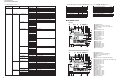

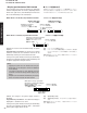

RX-V550/HTR-5750
RX-V450/HTR-5740/DSP-AX450
20
Top Cover
トップカバー
Front Panel Unit
フロントパネルユニット
CB309
CB306
CB505
CB863
1
1
3
3
3
2
2
Support/DSP
サポート/DSP
DSP P.C.B.
FUNCTION (2) P.C.B.
CB2
CB351
CB1
CB502
CB503
CB307
4
Cloth
布
CB354
CB351
CB503
MAIN (1) P.C.B.
MAIN (7) P.C.B.
MAIN (5) P.C.B.
POWER (1) P.C.B.
0
9
9
A
A
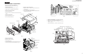
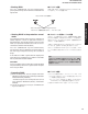
7. Removal of MAIN (1), MAIN (5), MAIN (7) and
POWER (1) P.C.B.s
a. Remove CB351, CB354 and CB503. (Fig. 5)
b. Remove 2 screws (9), 2 screws (0) and 3 screws (A).
(Fig. 5)
c. Remove MAIN (1), MAIN (5), MAIN (7) and POWER (1)
P.C.B.s.. (Fig. 5)
When checking the P.C.B.:
• Put a Cloth over the equipment. Put the MAIN (1), (5), (7)
and POWER (1) P.C.B.s together with the heat sink upright
on the Cloth and check them. (Fig. 6)
• Reconnect all cables (connectors) that have been
disconnected.
• When connecting the flat cable, use care for the polarity.
• The P.C.B. removed from the rear panel does not work
because its grounding is loose. Be sure to connect the
ground of each P.C.B. to the chassis or GND with a jumper
wire or the like.
Fig. 6
Fig. 5
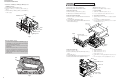
■ DISASSEMBLY PROCEDURES / 分解手順
HTR-5750 RX-V450/HTR-5740/DSP-AX450
Fig. 1
(Remove parts in the order as numbered.)
Disconnect the power cable from the AC outlet.
1. Removal of Top Cover
a. Remove 4 screws (1) and 4 screws (2). (Fig. 1)
b. Slide the Top Cover rearward to remove it. (Fig. 1)
2. Removal of Front Panel Unit
a. Remove 7 screws (3) and then slide the Front Panel Unit
forward. (Fig. 1)
b. Loosen the harness fixture fixing the cable.
c. Remove CB306, CB309, CB505 and CB863 and then remove
the Front Panel Unit. (Fig. 1)
(番号順に部品を取り外してください。)
AC電源コンセントから、電源コードを抜いてください。
1.トップカバーの外し方
a. 1のネジ4本、2のネジ4本を外します。(Fig. 1)
b. トップカバーを後方へスライドさせ、取り外します。(Fig. 1)
2. フロントパネルユニットの外し方
a. 3のネジ7本を外し、フロントパネルユニットを前 方 へ引き出しま
す。(Fig. 1)
b. ケーブルを固定している束線止めをゆるめます。
c. CB306、CB309、CB505、CB863を外し、フロントパネルユ
ニットを取り外します。(Fig. 1)
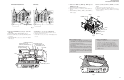
Fig. 2
3. DSP P.C.B.の外し方
a. 4のネジ1本を外します。(Fig. 2)
b. 5のネジ5本を外します。(Fig. 3)
c. CB2を外します。(Fig. 2)
d. FUNCTION(2) P.C.B.を上部に浮かせCB1を外します。(Fig.
2)
e. DSP P.C.B.をサポート/DSPと共に取り外します。(Fig. 2)
3. Removal of DSP P.C.B.
a. Remove 1 screw (4). (Fig. 2)
b. Remove 7 (HTR-5750), 5 (RX-V450, HTR-5740) screws (5).
(Fig. 3)
c. Remove CB2. (Fig. 2)
d. Lift up the FUNCTION (2) P.C.B. and remove the CB1. (Fig. 2)
e. Remove the DSP P.C.B. with the Support/DSP. (Fig. 2)