BGR AX-9 Natural Sound Stereo Integrated Amplifier Préampli/ampli de puissance stéréo de la série “Natural Sound” Natural Sound Stereo-Verstärker Natural Sound Integrerad Stereo Förstärkare Amplificatore integrato stereo a Suono Naturale Amplificador integrado estéreo de Sonido Natural Natural Sound Geïntegreerde Stereo Versterker OWNER’S MANUAL MODE D’EMPLOI BEDIENUNGSANLEITUNG BRUKSANVISNING MANUALE DI ISTRUZIONI MANUAL DE INSTRUCCIONES GEBRUIKSAANWIJZING
SUPPLIED ACCESSORIES ACCESSOIRES FOURNIS MITGELIEFERTES ZUBEHÖR MEDFÖLJANDE TILLBEHÖR ACCESSORI IN DOTAZIONE ACCESORIOS INCLUIDOS BIJGELEVERDE ACCESSOIRES ● ● ● ● ● ● ● ● ● ● ● ● ● ● Remote Control Transmitter Emetteur de télécommande Fernbedienung Fjärrkontroll Telecomando Transmisor del control remoto Afstandbediening ● ● ● ● ● ● ● YAMAHA HIFI SYSTEM REMOTE CONTROL TRANSMITTER AUX DIR A DIR B REC/PAUSE PLAY A/B – PRESET + A/B/C/D/E DISC PLAY MD TAPE TUNER CD PHONO SLEEP 2 POWER Aft
FEATURES English Thank you for selecting this YAMAHA stereo amplifier. ● 50W + 50W (8Ω) RMS Output Power, 0.03% THD, 20–20,000 Hz ● High Dynamic Power, Low Impedance Drive Capability ● PURE DIRECT Switch to Reproduce the Purest Source Sound ● Remote Control Capability CONTENTS Supplied Accessories .........................................................................................2 Caution ..............................................................................................................
CAUTION: READ THIS BEFORE OPERATING YOUR UNIT. 1. To assure the finest performance, please read this manual carefully. Keep it in a safe place for future reference. 2. Install this unit in a cool, dry, clean place – away from windows, heat sources, sources of excessive vibration, dust, moisture and cold. Avoid sources of humming (transformers, motors). To prevent fire or electrical shock, do not expose the unit to rain or water. 3. Never open the cabinet.
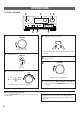
Battery installation Remote control transmitter operation range 2 English NOTES ABOUT THE REMOTE CONTROL TRANSMITTER Remote control sensor 1 Within approximately 6 m (19.7 feet) 3 30° Battery replacement If you find that the remote control transmitter must be used closer to the main unit, the batteries are weak. Replace both batteries with new ones. Notes ● Use only AA, R6, UM-3 batteries for replacement. ● Be sure the polarities are correct. (See the illustration inside the battery compartment.
CONNECTIONS Never plug in this unit and other components until all connections are completed. ● ● When making connections between this unit and other components, be sure all connections are made correctly, that is to say L (left) to L, R (right) to R, “+” to “+” and “–” to “–”. Also, refer to the owner’s manual for each component to be connected to this unit. If you have YAMAHA components numbered as 1, 2, 3, etc.
Connect the SPEAKERS terminals to your speakers with wire of the proper gauge, cut as short as possible. If the connections are faulty, no sound will be heard from the speakers. Make sure that the polarity of the speaker wires is correct, that is, + and – markings are observed. If these wires are reversed, the sound will be unnatural and will lack bass. Do not let the bare speaker wires touch each other and do not let them touch the metal parts of this unit as this could damage this unit and/or speakers.
CONTROLS AND THEIR FUNCTIONS FRONT PANEL 1 2 3 45 6 7 8 INPUT l NATURAL SOUND STEREO AMPLIFIER AX 9 VOLUME STANDBY/ON PURE TAPE DIRECT MONITOR AUX TAPE MD CD TUNER PHONO SLEEP 0 PHONES 9 0 SPEAKERS A B ON ON OFF OFF A PURE DIRECT B C 2 STANDBY/ON switch Press this switch to turn the power to this unit on. Press it again to turn this unit into the standby mode.
English REMOTE CONTROL TRANSMITTER The remote control transmitter provided with this unit is designed to control all the most commonly used functions of this unit. If the CD player, tuner or tape deck connected to this unit are YAMAHA components designed for remote control compatibility, then this remote control transmitter will also control various functions of each component.
OPERATIONS TO PLAY A SOURCE 2 3 1, 6 INPUT l NATURAL SOUND STEREO AMPLIFIER AX 9 VOLUME STANDBY/ON PURE TAPE DIRECT MONITOR AUX TAPE MD CD TUNER PHONO SLEEP 0 PHONES SPEAKERS A B ON ON OFF OFF 4 1 PURE DIRECT TAPE MONITOR BASS TREBLE 0 0 – 7 – + L R 7 4 VOLUME + l0 BALANCE Select the speakers to be used. SPEAKERS A B 0 l0 ON ON OFF OFF Set to the “0” position. 2 * If you use two speaker systems, press both the A and B switches. Turn the power on.
l NATURAL SOUND STEREO AMPLIFIER AX 9 1 2 INPUT VOLUME English TO RECORD A SOURCE TO TAPE (OR MD) STANDBY/ON PURE TAPE DIRECT MONITOR AUX TAPE MD CD TUNER PHONO SLEEP 0 PHONES SPEAKERS A B ON ON OFF OFF PURE DIRECT TAPE MONITOR BASS TREBLE 0 0 – + – + l0 BALANCE L R 4 1 3 Select the source to be recorded. Begin recording on the tape deck (or MD recorder etc.) connected to this unit.
Adjusting the BALANCE control Adjust the balance of the output volume to the left and right speakers to compensate for sound imbalance caused from speaker location or listening room conditions. Selecting the SPEAKER system Because one or two speaker systems can be connected to this unit, the SPEAKERS switches allow you to select speaker system A or B, or both at once. SPEAKERS BALANCE L R Adjusting the BASS and TREBLE controls BASS TREBLE 0 0 – BASS + – PURE DIRECT PURE DIRECT Lights up.
If the unit fails to operate normally, check the following points to determine whether the fault can be corrected by the simple measures suggested. If it cannot be corrected, or if the fault is not listed in the SYMPTOM column, disconnect the power cord and contact your authorized YAMAHA dealer or service center for help. SYMPTOM CAUSE REMEDY The unit fails to turn on when the STANDBY/ON switch is pressed, or turns into the standby mode suddenly soon after the power is turned on.
SPECIFICATIONS Minimum RMS Output Power per Channel 8 ohms, 20 Hz to 20 kHz, 0.03% THD .......................50W+50W Dynamic Power per Channel (by IHF Dynamic Headroom measuring method) 8/6/4/2 ohms.................................................78/88/100/112W Total Harmonic Distortion (20 Hz to 20 kHz) PHONO MM to REC OUT ...........................................0.02% CD/TUNER/TAPE/MD/AUX to SP OUT (25W/8 ohms)..0.02% Signal-to-Noise Ratio (IHF-A Network) PHONO MM (5 mV Input Shorted) ................
YAMAHA YAMAHA YAMAHA YAMAHA YAMAHA YAMAHA YAMAHA ELECTRONICS CORPORATION, USA 6660 ORANGETHORPE AVE., BUENA PARK, CALIF. 90620, U.S.A. CANADA MUSIC LTD. 135 MILNER AVE., SCARBOROUGH, ONTARIO M1S 3R1, CANADA ELECTRONIK EUROPA G.m.b.H. SIEMENSSTR. 22-34, 25462 RELLINGEN BEI HAMBURG, F.R. OF GERMANY ELECTRONIQUE FRANCE S.A. RUE AMBROISE CROIZAT BP70 CROISSY-BEAUBOURG 77312 MARNE-LA-VALLEE CEDEX02, FRANCE ELECTRONICS (UK) LTD. YAMAHA HOUSE, 200 RICKMANSWORTH ROAD WATFORD, HERTS WD1 7JS, ENGLAND SCANDINAVIA A.