AX-V401 Natural Sound Stereo Integrated Amplifier Préampli/ampli de puissance stéréo de la série “Natural Sound” Natural Sound Stereo-Verstärker Natural Sound Integrerad Stereo Förstärkare Amplificatore integrato stereo a Suono Naturale Amplificador integrado estéreo de Sonido Natural Natural Sound Geïntegreerde Stereo Versterker S OWNER’S MANUAL MODE D’EMPLOI BEDIENUNGSANLEITUNG BRUKSANVISNING MANUALE DI ISTRUZIONI MANUAL DE INSTRUCCIONES GEBRUIKSAANWIJZING
SUPPLIED ACCESSORIES ACCESSOIRES FOURNIS MITGELIEFERTE ZUBEHÖRTEILE MEDFÖLJANDE TILLBEHÖR ACCESSORI IN DOTAZIONE ACCESORIOS INCLUIDOS BIJGELEVERDE ACCESSOIRES ● ● ● ● ● ● ● Remote Control Transmitter Emetteur de télécommande Fernbedienungsgeber Fjärrkontrollsändare Trasmittente del telecomando Transmisor del control remoto Afstandbediening ● ● ● ● ● ● ● After unpacking, check that the following parts are contained. Après le déballage, vérifier que les pièces suivantes sont incluses.
FEATURES • • • • • • CONTENTS 55W + 55W (8Ω) RMS Output Power, 0.04% THD, 20–20,000 Hz High Dynamic Power, Low Impedance Drive Capability Continuously Variable Loudness Control Source Direct Switch to Reproduce the Purest Source Sound Video Signal Input/Output Capability Remote Control Capability Supplied Accessories .....................................................2 Caution ...........................................................................3 Connections ......................................
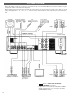
CONNECTIONS • Before attempting to make any connections to or from this unit, be sure to first switch OFF the power to this unit and to any other components to which connections are being made. • When making connections between this unit and other components, be sure all connections are made correctly, that is to say L (left) to L, R (right) to R, “+” to “+” and “–” to “–”. Also, refer to the owner’s manual for each component to be connected to this unit.
Connect the SPEAKERS terminals to your speakers with wire of the proper gauge, cut to be as short as possible. If the connections are faulty, no sound will be heard from the speakers. Make sure that the polarity of the speaker wires is correct, that is, + and – markings are observed. If these wires are reversed, the sound will be unnatural and will lack bass.
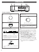
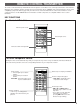
OPERATIONS 2 4 3 7 TO PLAY A SOURCE 1 1,6 5 VOLUME 6 Play the source. VOLUME 0 — dB ∞” position. Set to the “ 0 — dB POWER 2 Adjust to the desired output level. 7 3 Select a desired input source. (For video sources, turn the TV/monitor ON.) MONITOR VCR/TAPE 2 TAPE 1 INPUT LD/TV TUNER CD PHONO COPY * The indicator corresponding to the selected input source will illuminate.
ENGLISH 2 1,4 TO RECORD A SOURCE TO TAPE 1 Select the source to be recorded. MONITOR VCR/TAPE 2 TAPE 1 INPUT LD/TV CD TUNER PHONO COPY Notes ● VOLUME, BASS, TREBLE, BALANCE and LOUDNESS control settings have no effect on the material being recorded. ● To dub from tape to tape, only the following one way of dubbing can be performed. Note that when dubbing is performed from a VCR to an audio tape deck, only audio signals of the VCR will be dubbed to the audio tape deck.
Adjusting the BALANCE control Adjust the balance of the output volume to the left and right speakers to compensate for sound imbalance caused from speaker location or listening room conditions. Selecting the SPEAKER system Because one or two speaker systems can be connected to this unit, the SPEAKERS switches allow you to select speaker system A or B, or both at once.
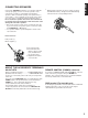
The remote control transmitter provided with this unit is designed to control all the most commonly used functions of the unit. If the CD player, tuner, turntable, equalizer, and tape deck connected to this unit are YAMAHA components designed for remote control compatibility (components with an S mark), then this remote control transmitter will also control various functions of each component.
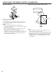
NOTES ABOUT THE REMOTE CONTROL TRANSMITTER Battery installation Remote control transmitter operation range 1 3 2 Remote control sensor Within approximately 7 m (23 feet) Battery replacement If you find that the remote control transmitter must be used closer to the main unit, the batteries are weak. Replace both batteries with new ones. Notes ● Use only AA, R6, UM-3 batteries for replacement. ● Be sure the polarities are correct. (See the illustration inside the battery compartment.
If the unit fails to operate normally, check the following points to determine whether the fault can be corrected by the simple measures suggested. If it cannot be corrected, or if the fault is not listed in the SYMPTOM column, disconnect the power cord and contact your authorized YAMAHA dealer or service center for help. SYMPTOM CAUSE REMEDY The unit fails to turn on when the POWER switch is pressed. Power cord is not plugged in or is not completely inserted. Firmly plug in the power cord.
SPECIFICATIONS Minimum RMS Output Power per Channel 8 ohms, 20 Hz to 20 kHz, 0.04% THD ..............................................55W+55W 6 ohms, 20 Hz to 20 kHz, 0.06% THD [Scandinavia and General models] ..............................................60W+60W 4 ohms, 20 Hz to 20 kHz, 0.1% THD [Australia and U.K. models] ..............................................68W+68W Dynamic Power per Channel (by IHF Dynamic Headroom measuring method) [General model] 8/6/4/2 ohms .............
YAMAHA YAMAHA YAMAHA YAMAHA YAMAHA YAMAHA YAMAHA ELECTRONICS CORPORATION, USA 6660 ORANGETHORPE AVE., BUENA PARK, CALIF. 90620, U.S.A. CANADA MUSIC LTD. 135 MILNER AVE., SCARBOROUGH, ONTARIO M1S 3R1, CANADA ELECTRONIK EUROPA G.m.b.H. SIEMENSSTR. 22-34, D-2084 RELLINGEN BEI HAMBURG, F.R. OF GERMANY ELECTRONIQUE FRANCE S.A. 17 RUE DES CAMPANULES, LOGNES 77321 MARNE LA VALLEE CEDEX 2, FRANCE ELECTRONICS (UK) LTD. YAMAHA HOUSE, 200 RICKMANSWORTH ROAD WATFORD, HERTS WD1 7JS, ENGLAND SCANDINAVIA A.B.