Using Cubase Cubase VST VST Using with DSP DSP Factory Factory with -1-
Documentation by Ernst Nathorst-Böös, Ludvig Carlson, Anders Nordmark, Roger Wiklander Additional assistance: Cecilia Lilja Quality Control: Cristina Bachmann, Sabine Pfeifer, Claudia Schomburg The information in this document is subject to change without notice and does not represent a commitment on the part of Steinberg Soft- und Hardware GmbH.
About the Yamaha DSP Factory The Yamaha DSP Factory is an audio hardware system for professional digital multitrack recording and mixing on personal computers. The core of this system is the DS2416 Digital Mixing Card, a PCI-bus audio card with professional specifications, extensive mixing capabilities and on-board EQ, dynamics and effects. It is possible to install and digitally connect two DS2416 cards in one computer.
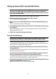
Setting up Cubase VST for use with DSP Factory ❐ This assumes that you have installed the DSP Factory hardware according to the instructions in the supplied manual, and tested that it runs properly under MacOS. Also, please note that the DSP Factory windows require a screen resolution of at least 1024 x 768 to be fully viewable. Before you can start working, you need to make a few settings: 1. Pull down the Options menu and select Audio Setup - System. The Audio System Setup dialog appears. 2.
Using the “DSP Factory Songs” Included with Cubase VST you will find a special DSP Factory folder containing two template Song files called “16 Channel Template Song” and “32 Channel Template Song”. These contain no music, but rather proper routing settings for 1 card and 2 card configurations, respectively.
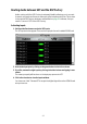
Routing Audio between VST and the DSP Factory Audio routing with the DSP Factory is extremely flexible, allowing you to connect channels, aux sends and buses to various physical outputs and inputs. This is done in the special DSP Factory windows, as described on page 29. However, first you need to “connect” VST to the DSP Factory: Activating Inputs 1. Pull down the Panels menu and select VST Inputs. The VST Inputs window appears. There are four Input pairs for each installed DS2416 card. 2.
Activating and Assigning Output Buses 1. Pull down the Panels menu and select VST Master Mixer. The VST Master window appears. In a single DS2416 card configuration, there are eight buses including the Master bus. 2. Activate all buses by clicking on their Active buttons. 3. Pull down the pop-up menus at the bottom of each Bus channel strip and check that each bus is assigned to the desired DS2416 output.
Selecting Inputs and Outputs for the Audio Channels This description assumes that you have set the number of audio channels so that it corresponds with the number of output bus channels (16 if you have one DS2416 card installed). It also assumes that you want each audio channel in VST assigned to a separate mixer channel strip in the DS2416 console.
The Default Signal Routing This section describes how signals are routed by default, when you first start using the DS2416 card with Cubase VST. If you wish you can change the signal routing, as described on page 29. However, this default routing allows you to perform basic playback and recording, and to use the built-in effects without having to change the routing. ❐ For additional info, please refer to the diagrams and list in the DS2416 documentation.
The Default Routing of signals from DS2416 into VST There are eight separate “lines” from the DS2416 card into Cubase VST. In VST, these correspond to the four Audio Input pairs (see page 6). In the DSP Factory Input Console window, the default configuration uses the eight bus sends to route signals from the audio card into VST (for recording).
Outputs Bus/Send in the DSP Factory Input Console Physical Output Master Stereo Out Left/Right DS2416 Analog Out Left/Right and DS2416 Digital Out Left/Right Aux Send 1 IOA/IOB Output 1 Aux Send 2 IOA/IOB Output 2 Aux Send 3 IOA/IOB Output 3 Aux Send 4 IOA/IOB Output 4 “IOA” and “IOB” are the connections to additional input/output units such as the AX44. For each DS2416 card, you can add two extra input/output units (IOA and IOB). In the case of the AX44, each unit has 4 inputs and outputs.
Opening the DSP Factory Windows When Cubase VST detects one or more DS2416 cards, a special “DSP Factory” submenu is added to the Panels menu. This contains all the DSP Factory windows: Below follows a brief description of each window. For detailed information, click on the page number links. • Input Console. This is the main mixer window for the DSP Factory system. Here is where you set levels, panning, eq and dynamics, activate buses and aux sends and select input sources for the DS channels.
The Input Console window The Input Console window is the main DSP Factory window. If you view the DSP Factory as an external digital mixer, feeding and receiving audio signals to and from VST, this window is the mixer panel. ❐ Static initial settings in the DSP Factory windows are saved with the Song. You can also automate your mixer actions, as described on page 36. About the Upper and Lower displays For each DS channel, there is a large number of controls and settings.
The Upper Display 1. Locate the dividing line between the Upper and Lower display for the channel strip. 2. Point at the small triangle pointing upward, and press the mouse button. A pop-up menu appears with the five modes for the Upper display. 3. Select one of the display modes. If you select the “Narrow” mode, the channel strip will be as narrow as possible to conserve screen space, with no controls in the Upper display (see below). The controls in the other modes are described on page 17.
Channel Controls in the Lower Display Bus On/Off buttons Aux Send On/Off buttons Pan Control Stereo link switch Level Display Level Fader Level Meter Fader Setting Channel Solo Channel Mute Input Selector Stereo Mix on/off switch The Lower Display in “Bus Assign”, “Aux Assign” and “Narrow” modes. Control Explanation Pan Control Sets the stereo position of the channel.
Control Explanation Bus On/Off buttons Use these to turn the Bus sends on or off for the channel. These buttons are “mirrored” in the Bus Send panel in the Upper display. Stereo Mix on/off switch This switch determines whether the channel is connected to the Stereo Mix (the master fader to the right on the Input Console panel) or not. You may want to deactivate this for channels which you have routed to separate outputs, using the Bus or Aux Sends.
Channel Controls in the Upper Display The Upper display in “EQ”, “Dynamics”, “Bus Send” and “Aux Send” modes. EQ Mode When EQ Mode is selected for the Upper Display, you have access to a four band parametric equalizer. Each EQ band has the following parameters: Bypass A Bypass-switch for the band. When the Bypass-indicator is lit, the EQ band is disabled. ❐ Q The Q value for the EQ band, ranging from10 (narrow) to 0.1 (wide) in 41 steps.
Selecting High/Low Pass or Shelving EQ types Normally, all four EQ bands are of the regular full parametric type, but you can switch the High and Low bands to Shelving or High/Low Pass Filter mode: • To select High/Low Shelving mode for the High or Low EQ band, turn the Q knob fully to the right. • To select High/Low Pass Filter mode for the High or Low EQ band, turn the Q knob fully to the left. This converts the High EQ band to a Low Pass Filter and the Low EQ band to a High Pass Filter.
Depending on which Dynamics Type you have selected, there are different parameters available. However, some general controls are available in all modes: Key-In pop-up menu In pop-up menu On button Click this to activate the Dynamics processor for the channel. Link button When this is activated, the dynamics processing is linked for the two channels in an odd-even pair. This means that a mix of the two channels is used to “trigger” the dynamics processor.
In the lower half of the Dynamics panel, you will find the actual controls: Parameter Description Threshold Determines the threshold level at which the dynamics processor is “triggered”. Whether signal levels above or below this level will trigger the processing, depends on the selected dynamics type. Ratio (Comp, Expander and Compander types only). Determines the amount of compression/expansion. For the Compander types, this determines the compression, while the expansion ratio is fixed.
Bus Send Mode ❐ The Bus Sends are always post-fader. This means that in many cases (e.g. when using the buses for recording into VST) there is no need to adjust the individual bus send levels - you only need to activate the desired buses in the Lower display (Bus Assign mode) and set the recording level using the faders. This assumes that you keep all bus send level knobs at their maximum setting. In this mode you can view and control the eight Bus Sends for the channel.
The Stereo Mix Section To the right in the Input Console window you will find the Stereo Mix section. This differs slightly from the regular channel strips: Lower Display In the Stereo Mix section, there are no different modes for the Lower display. It always contains a stereo master fader with a numerical display, stereo level meters and numeric level indicators, a balance control and a Mute button, for silencing the Stereo Mix output totally. The Mute button does not affect the buses or Aux sends.
The Common Panel To the left of the channel strips you will find a section with common controls: Control Description Read/Write buttons This works just like the Read and Write buttons in the VST Channel Mixer. To create an automated mix, you click Write and perform the desired mixing maneuvers, during playback or in Stop mode. To play your recorded mixer actions back, activate the Play button and start playback. For more details about automation, see page 36.
The Bus/Aux Console This window contains master level controls for the eight buses and six Aux sends, together with level meters and numerical level indicators. There are also Mute buttons for each bus/send. • The options for slow/fast metering and Peak Hold in the Input Console window affects the meters and indicators in the Bus/Aux Console as well.
The Channel Overview This window allows you to view and access all controls at the same time for a single channel. You select which channel to view by using the Channel Selection pop-up menu in the upper left corner. The controls in the Channel Overview are the same as in the Input Console window, with the addition of the following parameters: Attenuator Allows you to adjust the input signal gain, with a range of -96 to +12 dB. Delay Time Allows you to delay a channel by up to 2600 samples.
The FX Editor This window allows you to select effect types and make settings for the two onboard effect units (labelled “FX Unit 1” and “FX Unit 2”). The window can be opened either from the DSP Factory submenu on the Panels menu, or by clicking the FX Show button in the Input Console window. You use the FX Unit pop-up menu to select which unit to make settings for, and then choose an effect type for the selected unit using the FX Type pop-up menu (at the upper right corner).
The Output Patchbay This window allows you to view and change the output routing, i.e. which buses and sends are routed to which outputs, and also contains word clock synchronization settings, for when you use the DSP Factory in conjunction with external digital recorders or other audio hardware. Output Routing section Each bus or send can be routed to any output or any combination of outputs. However, it is not possible to route several different buses to the same output.
Word Clock Settings The right half of the Output Patchbay window contains word clock settings. These are used to determine which sample rate should be used for the audio playback and recording. Use the buttons to select one of the following options: ❐ Option Description Int 44.1 kHz The internal clock is used, with a sample rate of 44.1 kHz. Int 48 kHz The internal clock is used, with a sample rate of 48 kHz. ext. SI This can be used when you have another DS2416 card or an SW1000XG card installed.
Changing the Input Routing With the default routing of physical Inputs (see page 10), you only have access to the analog and digital inputs on the actual DS2416 card, not to any inputs on additional input/output units. If you have one or two input/output units installed, you may want to connect the inputs on these units to DS channels that normally take their input from VST. This is done using the Input pop-up menus in the Input Console window: 1. Open the Input Console window. 2.
Channel Input Options 1 VST 1 IOB2-1 2 VST 2 IOB2-2 3 VST 3 IOB2-3 4 VST 4 IOB2-4 5 VST 5 IOB2-5 6 VST 6 IOB2-6 7 VST 7 IOB2-7 8 VST 8 IOB2-8 9 VST 9 IOB1-1 SUB 1 IOA2-1 10 VST 10 IOB1-2 SUB 2 IOA2-2 11 VST 11 IOB1-3 SUB 3 IOA2-3 12 VST 12 IOB1-4 SUB 4 IOA2-4 13 VST 13 IOA1-1 SUB 5 IOA2-5 14 VST 14 IOA1-2 SUB 6 IOA2-6 15 VST 15 IOA1-3 SUB 7 IOA2-7 16 VST 16 IOA1-4 SUB 8 IOA2-8 17 Analog In L IOA1-1 SUB 1 IOA2-1 18 Analog In R IOA1-2 SUB
Changing the Output Routing It is possible to route each bus or send (except Aux 5-6) to any output or any combination of outputs. However, it is not possible to route several different buses to the same output. Output routing is done in the Output Patchbay window: 1. Open the Output Patchbay window. 2. Locate the output you want to access, in the list to the left. Note that the outputs listed are outputs pairs.
Single-Track Recording Recording a single mono or stereo Track in Cubase VST with the DSP Factory is easily done, using the default signal routing: Recording a Mono Track ❐ In this section we assume that you are recording a signal connected to one of the analog or digital inputs on the DS2416 card, and that you are monitoring using the analog or digital outputs on the card. 1. In Cubase VST, select the desired audio Track. 2.
Recording a Stereo Track ❐ In this section we assume that you are recording a stereo signal connected to the analog or digital inputs on the DS2416 card, and that you are monitoring using the analog or digital outputs on the card. 1. In Cubase VST, select the desired stereo audio Track. 2. Open the Channel Mixer and select different Inputs for the two channels, by holding down [Ctrl] and clicking the Input buttons at the top of their channel strips.
Recording with Effects If you like to add effects to the signal you are recording, proceed as follows: 1. Set up the controls as described above (for mono or stereo recording). 2. Activate Aux Sends 5 and/or 6 for the input channel(s), and set their send level knobs to medium values. If you want the sends to be Post fader, activate the Post buttons for the sends. 3. Make sure the FX Return channels are not muted or have their levels turned down. 4. Open the FX Editor window.
Multi-Track Recording The DSP Factory system makes it possible to record up to eight separate audio Tracks at the same time (in a setup with one DS2416 card). Proceed as follows: ❐ In this section we assume that you have at least one additional input/output unit installed, and that you are recording mono signals from several different inputs at the same time, while monitoring through the analog or digital outputs on the card. 1.
Automating the DSP Factory Your actions in the DSP Factory windows can be automated in the same straightforward way as in the Cubase VST Channel Mixer: • If you activate the Write button at the top right corner of the Input Console, your mixer actions will be written into a special “DS2416 Mix” Part. You can record your actions during playback or in stop mode, in which case the changes will be written at the current song position.
Mixing down to a Stereo Output Once you have finished a piece of music, you may want to mix it down to an external two track recorder (DAT, MD, tape, etc). This example describes how to mix down sixteen separate VST audio channels to stereo, adding the on-board effects, one external effect unit and the stereo output of a MIDI instrument. The external two track recorder is connected to the digital stereo output on the DS2416 with the analog output used for monitoring.
6. Open the Output Patchbay window and make sure the signals are routed in the following way: Output Bus/Aux Send Pair Comment IOA3/4 Aux 3/4 External effect send (only output 4 is used). Analog Stereo Monitoring. S/P DIF Stereo Two track recorder. 7. Check that your audio channels play back as desired and adjust EQ/Dynamics if necessary. You may already have created a complete automated mix, in which case everything should be playing back just the way you want it. 8.
Mixing down to a new Track in Cubase VST An alternative to mixing down to a separate two track recorder is to mix down to a new audio file. If you were using Cubase VST alone, you would use the Export Audio Tracks feature for this, but this cannot include the DSP Factory mixing and effects (since the DS2416 card actually is an external mixer - albeit within your computer). Instead you can re-record the mix to a new Stereo Track in Cubase VST, thereby creating a mixdown audio file.
Working with two DS2416 Cards If you have two DS2416 cards installed, these can be connected using the SI/SO (Serial In/Out) connections on the cards, giving you access to integrated 48-channel mixing with 4 separate on-board FX units. 1. Use the supplied serial cables to connect the SO output on card A to the SI input on card B, and vice versa. The two cards should be connected “both ways”. Follow the instructions in the documentation that was included with the cards. 2. Open the Output Patchbay window.
The Buses, Aux Sends and Stereo Mix on the Slave card will receive the signals from the corresponding buses on the Master card, and the signals will be summed. In the opposite direction, only Aux Send 3/4 from the Slave card will be connected to the Master card’s Aux bus. This makes it possible to access all four FX units from all channels, as described below. Due to this routing, it is not possible to record on all sixteen channels simply by using the buses.
Remote Controlling the DSP Factory Mixer It is possible to use a Yamaha 01V digital mixer to remote control the DSP Factory mixer in Cubase VST. This is done using the VST Remote function. Setting Up ❐ Make sure to read the section about the VST Remote function in the main manual as well, for general information about remote control in Cubase VST. 1. Connect the 01V to your MIDI Interface. The mixer should be connected “both ways” to allow feedback to indicators and motorized faders. 2.
About the Layouts As when you are using the 01V to control the VST mixer parameters, there are two different “Layouts” for controlling the DSP Factory Mixer in Cubase VST (there are also two Layouts for controlling the VST Mixer, as described in the main documentation). Which channels on the 01V control which DS-channels in Cubase VST, depends on the selected Layout. However, the controllable parameters for each “channel strip” are the same in each layout (see below).
Controllable Parameters Channels 1 to 20 • • • • • • • • • • Volume. Pan. Mute. Aux Send 1-6 (“01v Effect 1 and 2” correspond to Aux 5 and 6). EQ Freq, Gain and Q-values (four bands). Stereo Link switch. Attenuator. Phase Invert Switch. Bus Send On 1 to 4. Stereo Mix switch. FX Return Channels • • • • • • • Volume. Pan. Mute. Aux Send 1-4. EQ Freq, Gain and Q-values (four bands). Bus Send On 1 to 4. Stereo Mix switch. Stereo Mix Section • • • • Volume. Balance. Mute.
Index F A Fader 15 FX Editor 26 FX Return Channels 16 ASIO Drivers 4 Attenuator 25 Automation 36 Aux Assign Mode Controls 15 Selecting 13 Aux Send Mode Controls 21 Selecting 14 AX44 Audio Expansion Units 3 Input Console 13 Inputs Activating in VST 6 Default Routing 10 Routing 29 Selecting in VST 8 IOA/IOB 11 B L Bus Assign Mode Controls 15 Selecting 13 Bus Send Mode Controls 21 Selecting 14 Bus/Aux Console 24 Level Fader 15 Level Meter 15 Link (Dynamics Mode) 19 C I M Meter Buttons 23 Mixing dow
R W Read 23, 36 Recording Mono 32 Multi-Track 35 Stereo 33 With Effects 34 Remote Control 42 Routing Changing 29 Default 9 With two cards 40 Wordclock 28 Write 23, 36 Y Yamaha DS2416 Drivers 4 S Sample Rate 28 Solo 15 Stereo link 15 Stereo Mix 22 Stereo Mix on/off 16 SUB Inputs 41 SW1000XG Card 41 - 46 -