ⅺ̪ʑᄽ Español Ԋ₤იञᑨ English Pre-Amplifier Owner´s Manual Manual de instrucciones ͐ᮢ⦦ᆙሬ
English Thank you and congratulations on your purchase of this Yamaha product. ¡¡ You can enjoy the high-quality stereo sound of this preamplifier at home. ¡¡ This Owner’s Manual describes the unit’s features, connection procedures, and operations. ¡¡ To use the product properly and safely, we suggest that you read this manual and Safety Brochure (separate booklet) thoroughly. Keep the manual in a safe, accessible place for future reference.
Table of contents Features . . . . . . . . . . . . . . . . . . . . . . . . 2 Operations Supplied accessories . . . . . . . . . . . . . . . . 4 Turning the power on . . . . . . . . . . . . . . 28 Maintenance . . . . . . . . . . . . . . . . . . . . . 4 Selecting the input and output . . . . . . . . 28 Mirror-finish side panels . . . . . . . . . . . . 4 Selecting the input from the EXT.IN jacks . .
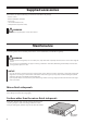
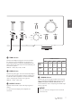
Supplied accessories Please make sure that the following accessories are included in the package. • • • • • Remote control Batteries (AAA, R03, UM-4) (x2) Power cord Owner’s Manual (this book) Safety Brochure (separate booklet) WARNING Do not use the supplied power cord for other devices. Maintenance To use this product for an extended period of time, we recommend that you maintain it regularly. WARNING • Check the power cord regularly to see if it is dusty. If so, wipe off the dust completely.
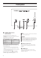
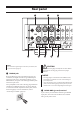
English Part Names and Functions This section lists the names and describes the function of various parts on the front and rear panels, and the remote control.
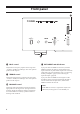
Front panel A. STANDBY/ON/OFF (Power) switch/ indicator Turns the power to the unit on (standby) or off. STANDBY/ON: Switches between standby and on using the A AMP key on the remote control. OFF: Turns the power to the unit off.
English D. TRIM selector Switches the headphone amp gain. The unit will adjust the volume level when headphones are plugged in to avoid sudden changes in volume by modifying the level balance between the audio output from the PHONES jack and from the speakers. Choices: −6 dB, 0 dB, +6 dB, +12 dB E. GAIN selector Switches the preamp gain. The unit will smoothly adapt to the power amp gain and speaker sensitivity, enabling you to make fine volume adjustments.
Front panel H. BASS control K. EXT. DIRECT switch/indicator Adjusts the low-frequency response in the range from −10 dB to +10 dB (in 0.5 dB steps). The center position produces a flat response. If you press the EXT. DIRECT switch once, the EXT. DIRECT indicator will light up, and the audio source input at the EXT. IN jacks will be output at the connected output jacks. For more information, refer to “Connecting another preamplifier” (page 23) and “Selecting the input and output” (page 28).
English L. INPUT selector/indicator N. AUDIO MUTE switch/indicator Enables you to select the input source to play back. Options are: PHONO, PHONO BAL, TUNER, CD, BAL 1, BAL 2, LINE 1, and LINE 2. The indicator for the selected input source lights up. Press this switch to reduce the current volume level by approximately 20 dB. The indicator will light up. Press again to restore the audio output to the previous volume level. The indicator will turn off.
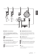
Rear panel Note For information regarding the connection procedure, refer to “Connections” (page 19). A. PHONO jacks RCA and XLR-type jacks. If the INPUT selector is set to PHONO, the signals at the RCA-type PHONO jacks will be the input source. If the INPUT selector is set to PHONO BAL, the signals at the XLR-type PHONO jacks will be the input source. Your preamplifier comes with a shorting plug installed on each RCA-type PHONO input jack.
English C. BAL 1/BAL 2 jacks E. PHASE selector These are two sets of XLR-type balanced input jacks. If the INPUT selector is set to BAL 1 or BAL 2, signals at the corresponding XLR jacks will be the input source. Specifies the HOT pin position for the XLR-type balanced input jacks (BAL 1 and BAL 2 jacks). NORMAL: Pin #2 is specified as HOT. INV.: Pin #3 is specified as HOT. For more information, refer to “Balanced and unbalanced connections” (page 14).
Rear panel G. CD jacks Note These are RCA input jacks. If the INPUT selector is set to CD, signals at these jacks will be the input source. Connect your CD player here. • Connect the LINE 2 IN jacks and LINE 2 OUT (recording) jacks to the same component. • The LINE 2 OUT (recording) jacks will not output any signals if the INPUT selector is set to LINE 2 or the EXT. DIRECT switch is pressed. H. LINE 1 jacks These are RCA input jacks.
English Note O. REMOTE IN/REMOTE OUT jacks The volume level is fixed. Operating the VOLUME control or GAIN selector on this unit will not change the volume level of the signal from the EXT. IN jacks. Adjust the volume level using the volume control on the component connected to the EXT. IN jacks. These are monaural mini jacks. Connect external components that support the remote function here. For more information, refer to “Remote connections” (page 25). L.
Balanced and unbalanced connections XLR jack (male) Lever This unit features XLR-type balanced jacks and RCAtype unbalanced input jacks. 2 Note Do not use balanced and unbalanced connections between two components simultaneously. Doing so would create a ground loop that could generate static and noise. Balanced connection XLR connector (female) 2 1 1 3 3 A balanced connection is designed to cancel and prevent unwanted noise.
If you are connecting an audio component that features only standard RCA jacks, use the RCA jacks on this unit for unbalanced connections. For unbalanced connections, unbalanced cables with RCA connectors should be used. These jacks and connectors do not feature a male or female design nor polarity differences. If the PHASE selector is set to NORMAL, pin #2 becomes Hot.
Remote control A. Infrared signal transmitter Outputs infrared control signals toward the unit. B. A AMP key AMP OPEN/CLOSE CD 1 2 Turns on the power to the unit or switches it to standby mode. For more information regarding standby mode, refer to “Front panel” (page 6). BAL BAL C. Input select keys UNBAL PHONO 1 2 LINE CD EXT.DIRECT TUNER BAND PRESET SOURCE LAYER VOLUME Enable you to select the input source to be played back.
E. A CD key H. VOLUME +/− keys Turns on the power to a connected Yamaha CD player, or switches it to standby mode. Adjust the volume level. OPEN/CLOSE key Opens or closes the disc tray of a connected Yamaha CD player. For more information, refer to the owner’s manual for your CD player. The VOLUME +/− keys on the remote control will not affect the volume level if EXT. DIRECT is selected as the input source.
Installing batteries in the remote control 1 2 Remove the battery compartment cover. Insert two batteries (AAA, R03, UM-4) according to the polarity markings (+ and −) on the inside of the battery compartment. 1 2 3 CAUTION • Do not use a new and old batteries at the same time. Otherwise, fire, burns, or irritation due to leaking battery liquid might be caused. • Do not use two different types of batteries at the same time.
English Connections This section explains how to connect the unit to an audio source, such as a tuner or CD player, and a power amplifier. CAUTION Turn off the power to all components before making any connections. NOTICE • Do not use balanced and unbalanced connections between two components simultaneously. Doing so would create a ground loop that could generate static and noise. • If you are planning to connect external components, read and follow the instruction manuals for those components.
Connecting an external component Turntable Turntable Network audio player 20 CD player CD player Tuner BD player Hard disk recorder, etc.
Power amplifier AV amplifier, etc. Power amplifier Active subwoofer English Other preamplifier NOTICE Do not use balanced and unbalanced connections between two components simultaneously. Doing so would create a ground loop that could generate static and noise.
Connecting a turntable Connect your turntable to the PHONO jacks on this unit. The unit provides XLR-type balanced jacks and RCAtype unbalanced input jacks. Balanced connection Turntable Connecting a recording component You can connect a recording device, such as a hard disk recorder to the unit, and record audio input from the unit. Connect the recording component to both LINE 2 IN jacks and LINE 2 OUT (recording) jacks.
Connecting a power amplifier and an active subwoofer If you connect the output of another preamplifier to the EXT. IN jacks on this unit and press the EXT. DIRECT switch, the source signal will pass through the unit and will be output to the connected power amplifier. The source signal input at the balanced EXT. IN jacks will be output at the balanced BAL jacks. The source signal input at the unbalanced EXT. IN jacks will be output at the LINE 1 and LINE 2 jacks.
Trigger connections Controlling the power on-andoff operation of a connected component, such as a power amplifier, in sync with this unit Controlling the unit’s power onand-off operation in sync with a connected component, such as an AV receiver You can control the power on-and-off operation of a connected component, such as a Yamaha CD player or power amplifier, in sync with this unit. Use a system cable to connect the unit’s TRIGGER OUT jack to the connected component’s TRIGGER IN jack.
Operating the unit from another room Remote connection between Yamaha components If you connect an infrared receiver and transmitter to the unit’s REMOTE IN/OUT jacks, you will be able to operate the unit and/or external component from another room, using the supplied remote control. If you have another Yamaha component that supports remote connections, as this unit does, an infrared transmitter is not necessary.
Connecting the power cord After all connections are complete, make sure that the STANDBY/ON/OFF (Power) switch is turned off, then plug the power cord into the AC IN connector of the unit, and then plug the power cord into the AC outlet. Supplied power cord C-5000 Rear panel CAUTION • Do not use an AC outlet that is so loose that the plug does not stay firmly in place. Otherwise, fire, electric shock, or burning might be caused.
English Operations This section explains basic operating procedures. You can follow these procedures to take advantage of the unit’s functions. These procedures are intended only as examples.
Turning the power on CAUTION Be sure to lower the volume level to minimum before turning the power on. Selecting the input and output Select a pair of output jacks using the OUTPUT selector. Turn the power on by setting the STANDBY/ON/OFF (Power) switch on the front panel to STANDBY/ON. All jacks Off Only BAL jacks Only LINE 1 jacks Only LINE 2 jacks Select the audio source using the INPUT selector. If the unit is in standby mode, you can also turn the power on using the remote control.
Adjusting the turntable input setting Selecting the input from the EXT.IN jacks English PHONO selector Set the PHONO selector according to the turntable cartridge. Options for turntable cartridge Press the EXT. DIRECT switch. The EXT. DIRECT indicator will light up. The INPUT selector setting will be disabled, and the audio source input from the EXT. IN jacks will be output at a pair of the output jacks.
Adjusting the volume level Subsonic filter Turn on the SUBSONIC FILTER switch to apply the subsonic filter, as needed. A resonating turntable tone arm or a warped vinyl record could cause a very low frequency rumble (subsonic noise) that might apply load and damage to the speakers. A subsonic filter will cut such noise to protect the speakers. Set the gain using the GAIN selector so that you can make fine volume adjustments. Gain Adjust the volume level using the VOLUME control.
Adjusting the tone Lowering the volume level momentarily Adjust the volume level balance between the left and right speakers using the BALANCE control. English Press the AUDIO MUTE switch to reduce the current volume level by approximately 20 dB. Press the switch again to restore the previous volume level. Adjust the volume level of the high and low ranges using the BASS and TREBLE control.
Connecting headphones If headphones are connected to the PHONES jack, no signal will be output at the output jacks (BAL, LINE 1, and LINE 2 output jacks) on the rear panel. Use the TRIM selector to switch the headphone amp gain so you can adjust the level balance between the audio output from the PHONES jack and the speakers to avoid sudden changes in volume. Note If EXT. DIRECT is selected, no signal will be output from the PHONES jack.
English Reference Materials 33
General specifications Rated output voltage/output impedance (Input 200 mV, 20 Hz to 20 kHz, THD 0.01%) BAL (BYPASS). . . . . . . . . . . . . . . . . . . 2 Vrms/150Ω BAL (ATT. −6dB). . . . . . . . . . . . . . . . . 1 Vrms/150Ω LINE 1/LINE 2. . . . . . . . . . . . . . . . . . . 1 Vrms/150Ω LINE 2 OUT (recording). . . . . . . 200 mVrms/1.2 kΩ Total harmonic distortion plus noise (JEITA, input 0.5 V, 20 Hz to 20 kHz) BAL 1/BAL 2/TUNER/CD/LINE 1/LINE 2 IN → BAL/LINE 1/LINE 2 . . . . . . . . . . . . . . . . .
Headphone jack rated output power (1 kHz, 32Ω, 0.2% THD) . . . . . . . . . . . . . . . . . . . . . . . . . . . 35 mW + 35 mW English RIAA equalization deviation MC/MM . . . . . . . . . . . . . . . . . . . . . . . . . . . . ±0.5 dB Subsonic filter characteristics MC/MM . . . . . . . . . . . . . . . . . . . . . . . . . 15 Hz/−3 dB Power supply [Models for U.S.A. and Canada]. . . AC 120 V, 60 Hz [Model for China]. . . . . . . . . . . . . . AC 220 V, 50 Hz [Model for Korea]. . . . . . . . . . . . . .
EXT. IN LINE 2 OUT (recording) TUNER /CD LINE 1/ LINE 2 PHONO PHONO BAL 2 BAL 1 INPUT SUB TRANSFORMER POWER RELAY Relay BAL→UNBAL ±32V ±81V INDEPENDENT CONSTANT BASS MIDDLE TREBLE VOLUME TONE CONTROL +99V +12V CURRENT POWER SUPPLY TOROIDAL TRANSFORMER SUBSONIC ON / THROUGH TONE CONTROL ON / THROUGH INDEPENDENT REGULATED POWER SUPPLY (for AUDIO) MOTOR VOL/ RELAY BAL Normal / UNBAL: 18.6dB BAL ATT: 12.
Audio characteristics Frequency response (tone control) 14 Response (dB) 10 +10dB 8 +8dB 6 +6dB 4 +4dB 2 +2dB 0 ±0dB English 12 –2dB –2 –4dB –4 –6dB –6 –8dB –8 –10dB –10 –12 –14 10 20 30 50 100 200 300 500 1k 2k 3k 5k 10k 20k 30k 50k 100k Frequency (Hz) Total harmonic distortion (PHONO) 10 5 2 1 0.5 THD + N Ratio (%) 0.2 0.1 20 Hz 0.05 1 kHz 20 kHz 0.02 0.01 0.005 0.002 0.001 0.0005 0.0002 0.
Frequency response (subsonic filter) 10 5 THROUGH Response (dB) 0 –5 ON –10 –15 –20 –25 5 10 20 30 50 100 200 300 500 1k 2k 3k 5k 10k 20k 30k 50k 100k Frequency (Hz) Volume curve 10 0 GAIN selector: –6 dB –20 Volume Level (dB) GAIN selector: 0 dB –40 GAIN selector: –12 dB –60 –80 –100 –110 0.00 50.00 100.00 150.00 Volume control (degree) 38 200.00 250.00 300.
Troubleshooting Refer to the table below if this unit does not function properly. If the instructions below do not help, or if the problem you are experiencing is not listed below, turn off the unit, disconnect the power cord, and contact the nearest authorized Yamaha dealer or service center. Cause Remedy See page The power cord is not connected to the AC IN connector on the rear panel or is not plugged into an AC outlet. Connect the power cord firmly.
Remedy See page Incorrect input or output cable connections. Connect the cables properly. If the problem persists, the cables might be defective. 20 The turntable is not grounded to the GND terminal. Connect the turntable to the GND terminal of this unit. 22 Both balanced and line cables are being used simultaneously between two components. Do not use both balanced and line cables simultaneously between two components. Doing so would create a ground loop that could generate static and noise.
Index O AC IN jack . . . . . . . . . . . . . . . . . . . . . . . . . . . . . . . Adjusting the turntable input . . . . . . . . . . . . . . . . . ATTENUATOR selector . . . . . . . . . . . . . . . . . . . . . AUDIO MUTE switch . . . . . . . . . . . . . . . . . . . . . . AUTO POWER STANDBY switch . . . . . . . . . . . . 26 29 30 31 13 BAL 1 jack . . . . . . . . . . . . . . . . . . . . . . . . . . . . . . . BAL 2 jack . . . . . . . . . . . . . . . . . . . . . . . . . . . . . . . BALANCE control . . .
Español Gracias y enhorabuena por la compra de este producto Yamaha. ¡¡ Puede disfrutar del sonido estéreo de calidad alta de este preamplificador en casa. ¡¡ En este Manual del propietario se describen las funciones, los procedimientos de conexión y las operaciones de la unidad. ¡¡ Para utilizar el producto de forma adecuada y segura, le sugerimos que lea detenidamente este manual y el Folleto de seguridad (folleto independiente).
Contenido Acerca de este manual . . . . . . . . . . . . . . 42 Accesorios suministrados . . . . . . . . . . . . 44 Mantenimiento . . . . . . . . . . . . . . . . . . 44 Paneles laterales con acabado de espejo . . 44 Superficies distintas de los paneles laterales con acabado de espejo . . . . . . . 44 Nombres y funciones de las piezas Panel delantero . . . . . . . . . . . . . . . . . . 46 Panel trasero . . . . . . . . . . . . . .
Accesorios suministrados Asegúrese de que el embalaje incluye los accesorios siguientes. • • • • • Mando a distancia Pilas (AAA, R03, UM-4) (x2) Cable de alimentación Manual de instrucciones (este libro) Folleto de seguridad (folleto independiente) ADVERTENCIA No utilice el cable de alimentación suministrado para otros dispositivos. Mantenimiento Para utilizar este producto durante un periodo prolongado, se recomienda realizar un mantenimiento periódico.
Español Nombres y funciones de las piezas En esta sección se enumeran los nombres y se describen las funciones de las distintas piezas de los paneles delantero y trasero, así como del mando a distancia.
Panel delantero A. Interruptor/indicador STANDBY/ON/ OFF (alimentación) Activa (espera) o desactiva la alimentación de la unidad. STANDBY/ON: cambia entre el modo de espera y el activado usando la tecla A AMP del mando a distancia. OFF: desactiva la alimentación de la unidad.
Español D. Selector TRIM Cambia la ganancia del amplificador de auriculares. La unidad ajustará el nivel de volumen cuando los auriculares estén conectados para evitar cambios repentinos de volumen modificando el balance de nivel entre la salida de audio procedente del jack PHONES y de los altavoces. Opciones: −6 dB, 0 dB, +6 dB, +12 dB E. Selector GAIN Cambia la ganancia del preamplificador.
Panel delantero H. Control BASS K. Interruptor/indicador EXT. DIRECT Ajusta la respuesta de frecuencia baja en la gama de −10 dB a +10 dB (en pasos de 0,5 dB). La posición central produce una respuesta plana. Si pulsa el interruptor EXT. DIRECT una vez, el indicador EXT. DIRECT se iluminará, y la entrada de fuente de audio en los jacks EXT. IN se emitirá por los jacks de salida conectados.
Español L. Selector/indicador INPUT N. Interruptor/indicador AUDIO MUTE Permite seleccionar la fuente de entrada que se va a reproducir. Las opciones son: PHONO, PHONO BAL, TUNER, CD, BAL 1, BAL 2, LINE 1 y LINE 2. El indicador para la fuente de entrada seleccionada se ilumina. Pulse este interruptor para reducir el nivel de volumen actual 20 dB aproximadamente. El indicador se iluminará. Púlselo de nuevo para reponer la salida de audio al nivel de volumen anterior.
Panel trasero Nota Para obtener información acerca del procedimiento de conexión, consulte “Conexiones” (página 59). A. Jacks PHONO Jacks de tipo RCA y XLR. Si el selector INPUT se ha establecido en PHONO, las señales en los jacks PHONO de tipo RCA serán la fuente de entrada. Si el selector INPUT se ha establecido en PHONO BAL, las señales en los jacks PHONO de tipo XLR serán la fuente de entrada.
Español C. Jacks BAL 1/BAL 2 E. Selector PHASE Se trata de dos juegos de jacks de entrada balanceada de tipo XLR. Si el selector INPUT se ha establecido en BAL 1 o BAL 2, las señales en los jacks XLR correspondientes serán la fuente de entrada. Especifica la posición del contacto con corriente para los jacks de entrada balanceada de tipo XLR (jacks BAL 1 y BAL 2). NORMAL: se especifica que el contacto n.º 2 tiene corriente. INV.: se especifica que el contacto n.º 3 tiene corriente.
Panel trasero G. Jacks CD Nota Se trata de jacks de entrada RCA. Si el selector INPUT se ha establecido en CD, las señales en estos jacks serán la fuente de entrada. Conecte el reproductor de CD aquí. • Conecte los jacks LINE 2 IN y los jacks LINE 2 OUT (grabación) al mismo componente. • Los jacks LINE 2 OUT (grabación) no emitirán señales si el selector INPUT se ha establecido en LINE 2 o el interruptor EXT. DIRECT está pulsado. H. Jacks LINE 1 Se trata de jacks de entrada RCA.
Español Nota O. Jacks REMOTE IN/REMOTE OUT El nivel de volumen es fijo. Al manipular el control VOLUME o el selector GAIN en esta unidad no cambiará el nivel de volumen de la señal procedente de los jacks EXT. IN. Ajuste el nivel de volumen con el control de volumen del componente conectado a los jacks EXT. IN. Se trata de mini jacks monaurales. Conecte componentes externos compatibles con la función remota aquí.
Conexiones balanceadas y no balanceadas Jack XLR (macho) Palanca Esta unidad presenta jacks balanceados de tipo XLR y jacks de entrada no balanceada de tipo RCA. 2 Nota No utilice conexiones balanceadas y no balanceadas entre dos componentes simultáneamente. Si lo hace se creará un bucle a tierra que podría generar estática y ruido. Conexión balanceada Una conexión balanceada está diseñada para cancelar y evitar el ruido no deseado.
Conexión no balanceada Si va a conectar un componente de audio que solo incluye jacks RCA estándar, utilice los jacks RCA de esta unidad para conexiones no balanceadas. Para conexiones no balanceadas, se deben utilizar cables no balanceados con conectores RCA. Estos jacks y conectores no presentan un diseño de tipo macho o hembra ni diferencias de polaridad. Español Si el selector PHASE se establece en NORMAL, el contacto n.º 2 recibe corriente.
Mando a distancia A. Transmisor de señales infrarrojas Emite señales infrarrojas de control hacia la unidad. B. Tecla A AMP AMP OPEN/CLOSE CD 1 2 Enciende la alimentación de la unidad o cambia al modo de espera. Para obtener más información sobre el modo de espera, consulte “Panel delantero” (página 46). BAL BAL C. Teclas de selección de entrada UNBAL PHONO 1 2 LINE CD EXT.
E. Tecla A CD H. Teclas VOLUME +/− Enciende la alimentación de un reproductor de CD Yamaha conectado o lo cambia al modo de espera. Ajuste el nivel del volumen. OPEN/CLOSE Abre o cierra la bandeja del disco de un reproductor de CD Yamaha conectado. Para obtener más información, consulte el manual del propietario de su reproductor de CD. Las teclas VOLUME +/− en el mando a distancia no afectarán al nivel de volumen si EXT. DIRECT está seleccionado como la fuente de entrada.
Instalación de las pilas en el mando a distancia 1 2 Retire la tapa del compartimento de las pilas. Introduzca las dos pilas (AAA, R03, UM-4) teniendo en cuenta las marcas de polaridad (+ y −) del interior del compartimento de las pilas. 1 2 3 Vuelva a colocar la tapa del compartimento de las pilas. ATENCIÓN • No utilice nuevas y antiguas al mismo tiempo. De lo contrario, podrían producirse incendios, quemaduras o irritaciones debido a la fuga de líquido de las pilas.
Español Conexiones En esta sección se describe cómo conectar la unidad a una fuente de audio, como un sintonizador o un reproductor de CD, y a un amplificador de potencia. ATENCIÓN Desactive la alimentación de todos los componentes antes de realizar conexiones. AVISO • No utilice conexiones balanceadas y no balanceadas entre dos componentes simultáneamente. Si lo hace se creará un bucle a tierra que podría generar estática y ruido.
Conexión de un componente externo Giradiscos Giradiscos Reproductor de CD Reproductor de audio de red 60 Reproductor de CD Sintonizador Reproductor de BD Grabador de disco duro, etc.
Amplificador de potencia Altavoz de subgraves activo Español Otro preamplificador Amplificador AV, etc. Amplificador de potencia AVISO No utilice conexiones balanceadas y no balanceadas entre dos componentes simultáneamente. Si lo hace se creará un bucle a tierra que podría generar estática y ruido.
Conexión de un giradiscos Conecte el giradiscos a los jack PHONO de esta unidad. La unidad proporciona jacks balanceados de tipo XLR y jacks de entrada no balanceada de tipo RCA. Conexión balanceada Giradiscos Conexión de un componente de grabación Puede conectar un dispositivo de grabación, como un grabador de disco duro, a la unidad y grabar la entrada de audio procedente de la unidad. Conecte el componente de grabación a los jacks LINE 2 IN y los jacks LINE 2 OUT (grabación).
Conexión de otro preamplificador Si conecta la salida de otro preamplificador a los jacks EXT. IN de esa unidad y pulsa el interruptor EXT. DIRECT, la señal de fuente atravesará la unidad y se emitirá por el amplificador de potencia conectado. La entrada de señal de fuente en los jacks EXT. IN balanceados se emitirá por los jacks BAL balanceados. La entrada de señal de fuente en los jacks EXT. IN no balanceados se emitirá por los jacks LINE 1 y LINE 2.
Conexiones de activación Control de la operación de encendido y apagado de un componente conectado, como un amplificador de potencia, de manera sincronizada con esta unidad Puede controlar la operación de encendido y apagado de un componente conectado, como un reproductor de CD Yamaha o un amplificador de potencia, de manera sincronizada con esta unidad. Utilice un cable del sistema para conectar el jack TRIGGER OUT de la unidad al jack TRIGGER IN del componente conectado.
Control de la unidad desde otra habitación Conexión remota entre componentes Yamaha Si conecta un receptor y un transmisor de señales infrarrojas a los jacks REMOTE IN/OUT de la unidad, podrá controlar la unidad o un componente externo desde otra habitación con el mando a distancia suministrado. Si dispone de otro componente Yamaha compatible con conexiones remotas, como es el caso de esta unidad, no es necesario un transmisor de infrarrojos.
Conexión del cable de alimentación Una vez realizadas todas las conexiones, asegúrese de que el interruptor STANDBY/ON/OFF (alimentación) está desactivado y, a continuación, enchufe el cable de alimentación al conector AC IN de la unidad y luego enchúfelo a la toma de CA.
Español Operaciones En esta sección se describen los procedimientos básicos de funcionamiento. Puede seguir estos procedimientos para aprovechar las funciones de la unidad. Estos procedimientos se proporcionan simplemente como ejemplos.
Encendido de la unidad Selección de la entrada y la salida Seleccione una pareja de jacks de salida con el selector OUTPUT. ATENCIÓN Asegúrese de bajar el nivel de volumen al mínimo antes de activar la alimentación. Active la alimentación estableciendo el interruptor STANDBY/ON/OFF (alimentación) en el panel delantero en STANDBY/ON. Todos los jacks Apagado Solo los jacks BAL Solo los jacks LINE 1 Solo los jacks LINE 2 Seleccione la fuente de audio con el selector INPUT.
Selección de la entrada desde los jacks EXT.IN Selección del ajuste de entrada del giradiscos Selector PHONO Ajuste el selector PHONO en función del cartucho del giradiscos. Español Opciones para cartucho del giradiscos Pulse el interruptor EXT. DIRECT. El indicador EXT. DIRECT se iluminará. El ajuste del selector INPUT se desactivará, y la entrada de fuente de audio desde los jacks EXT. IN se emitirá por una pareja de los jacks de salida.
Filtro subsónico Active el interruptor SUBSONIC FILTER para aplicar el filtro subsónico, en caso necesario. Un brazo fonocaptor de giradiscos resonante o un disco de vinilo combado pueden provocar una reverberación de frecuencia muy baja (ruido subsónico) que podría aplicar carga y daños a los altavoces. Un filtro subsónico cortará dicho ruido para proteger los altavoces. Ajuste del nivel de volumen Ajuste la ganancia usando el selector GAIN para poder realizar ajustes precisos del volumen.
Ajuste del tono Bajada momentánea del nivel de volumen Ajuste el balance de nivel de volumen entre los altavoces izquierdo y derecho usando el control BALANCE. Español Pulse el interruptor AUDIO MUTE para reducir el nivel de volumen actual 20 dB aproximadamente. Pulse el interruptor de nuevo para reponer el nivel de volumen anterior. Ajuste el nivel de volumen de las gamas altas y bajas usando los controles BASS y TREBLE.
Conexión de auriculares Si hay auriculares conectados al jack PHONES, no se emitirá ninguna señal por los jacks de salida (jacks de salida BAL, LINE 1 y LINE 2) en el panel trasero. Utilice el selector TRIM para cambiar la ganancia del amplificador de auriculares de modo que pueda ajustar el balance de nivel entre la salida de audio del jack PHONES y los altavoces para evitar cambios repentinos de volumen. Nota Si se selecciona EXT. DIRECT, no se emitirá ninguna señal por el jack PHONES.
Español Materiales de referencia 73
Especificaciones generales Tensión de salida nominal/impedancia de salida (entrada a 200 mV, de 20 Hz a 20 kHz, THD 0,01%) BAL (BYPASS). . . . . . . . . . . . . . . . . . . 2 Vrms/150 Ω BAL (ATT. −6dB). . . . . . . . . . . . . . . . . 1 Vrms/150 Ω LINE 1/LINE 2. . . . . . . . . . . . . . . . . . . 1 Vrms/150 Ω LINE 2 OUT (grabación) . . . . . . 200 mVrms/1,2 kΩ Distorsión armónica total más ruido (JEITA, entrada 0,5 V, de 20 Hz a 20 kHz) BAL 1/BAL 2/TUNER/CD/LINE 1/LINE 2 IN → BAL/LINE 1/LINE 2 . . . . .
Potencia de salida nominal de la toma de auriculares (1 kHz, 32 Ω, 0,2% THD) . . . . . . . . . . . . . . . . . . . . . . . . . . . 35 mW + 35 mW Desviación de ecualización RIAA MC/MM . . . . . . . . . . . . . . . . . . . . . . . . . . . . ±0,5 dB Características del filtro subsónico Español MC/MM . . . . . . . . . . . . . . . . . . . . . . . . . 15 Hz/−3 dB Alimentación [Modelos para EE. UU. y Canadá]. . . . 120 V CA, 60 Hz [Modelo para China]. . . . . . . . . . . . 220 V CA, 50 Hz [Modelo para Corea]. .
EXT. IN LINE 2 OUT (recording) TUNER /CD LINE 1/ LINE 2 PHONO PHONO BAL 2 BAL 1 INPUT SUB TRANSFORMER POWER RELAY Relay BAL→UNBAL ±32V ±81V INDEPENDENT CONSTANT BASS MIDDLE TREBLE VOLUME TONE CONTROL +99V +12V CURRENT POWER SUPPLY TOROIDAL TRANSFORMER SUBSONIC ON / THROUGH TONE CONTROL ON / THROUGH INDEPENDENT REGULATED POWER SUPPLY (for AUDIO) MOTOR VOL/ RELAY BAL Normal / UNBAL: 18.6dB BAL ATT: 12.
Características de audio Respuesta de frecuencia (control de tono) 14 10 +10dB 8 +8dB 6 +6dB 4 +4dB 2 +2dB 0 ±0dB Español Response (dB) 12 –2dB –2 –4dB –4 –6dB –6 –8dB –8 –10dB –10 –12 –14 10 20 30 50 100 200 300 500 1k 2k 3k 5k 10k 20k 30k 50k 100k Frequency (Hz) Distorsión armónica total (PHONO) 10 5 2 1 0.5 THD + N Ratio (%) 0.2 0.1 20 Hz 0.05 1 kHz 20 kHz 0.02 0.01 0.005 0.002 0.001 0.0005 0.0002 0.
Filtro subsónico 10 5 THROUGH Response (dB) 0 –5 ON –10 –15 –20 –25 5 10 20 30 50 100 200 300 500 1k 2k 3k 5k 10k 20k 30k 50k 100k Frequency (Hz) · Curva de volumen 10 0 GAIN selector: –6 dB –20 Volume Level (dB) GAIN selector: 0 dB –40 GAIN selector: –12 dB –60 –80 –100 –110 0.00 50.00 100.00 150.00 Volume control (degree) 78 200.00 250.00 300.
Resolución de problemas Consulte la tabla siguiente si esta unidad no funciona bien. Si las instrucciones siguientes no ayudan a solucionar el problema, o si el problema no es uno de los que aparecen en la siguiente lista, apague la unidad, desconecte el cable de alimentación y póngase en contacto con el centro de servicio o distribuidor Yamaha autorizado más cercano.
Problema Causa Solución Consulte la página Conexiones incorrectas de los cables de entrada o salida. Conecte los cables correctamente. Si el problema persiste, es posible que los cables estén defectuosos. 60 El giradiscos no está conectado a tierra en el terminal GND. Conecte el giradiscos al terminal GND de esta unidad. 62 Se están utilizando simultáneamente cables balanceados y de línea entre dos componentes. No utilice cables balanceados y de línea simultáneamente entre dos componentes.
Índice L Activación, conexión . . . . . . . . . . . . . . . . . . . . . . . Ajuste de la entrada del giradiscos . . . . . . . . . . . . . Altavoz de subgraves, conexión . . . . . . . . . . . . . . . Amplificador de potencia, conexión . . . . . . . . . . . . ATTENUATOR, selector . . . . . . . . . . . . . . . . . . . . AUDIO MUTE, interruptor . . . . . . . . . . . . . . . . . . Auriculares, conexión . . . . . . . . . . . . . . . . . . . . . . . AUTO POWER STANDBY, interruptor . . . . . . . .
ⅺ̪ʑᄽ 感謝您購買本 Yamaha 產品。 ¡ 您可在家中享受此前級擴大機帶來的高品質立體聲。 ¡ 本使用說明書說明此裝置的功能、連線程序及操作方式。 ¡ 為正確且安全地使用本產品,我們建議您完整閱讀本手冊及安全手冊 ( 獨立小冊子 )。 請妥善保管本手冊,以供日後參考之用。 您可從以下 Yamaha 網站下載本手冊 PDF 版本。 https://download.yamaha.
目錄 功能. . . . . . . . . . . . . . . . . . . . . . . . . . 82 操作方式 關於本手冊 . . . . . . . . . . . . . . . . . . . . . 82 隨附配件 . . . . . . . . . . . . . . . . . . . . . . 84 開啟電源 . . . . . . . . . . . . . . . . . . . . . 108 保養. . . . . . . . . . . . . . . . . . . . . . . . . . 84 選擇輸入及輸出 . . . . . . . . . . . . . . . . . 108 鏡面側面板. . . . . . . . . . . . . . . . . . . . 84 選擇來自 EXT.IN 插孔的輸入. . . . . . . . 109 鏡面側面板以外的表面 . . . . . . . . . . . . 84 調整唱盤輸入設定 . . . . . . . . . . . . . . . 109 PHONO 選擇器 . . .
隨附配件 請務必確認商品包裝內含下列配件。 • • • • • 遙控器 電池 (AAA、R03、UM-4) (x2) 電源線 使用說明書 ( 本書 ) 安全手冊 ( 獨立小冊子 ) 警告 請勿將隨附電源線用於其他裝置。 保養 為延長本產品的使用時間,我們建議您定期保養本產品。 警告 • 請定期確認電源線是否骯髒。如有,請將髒汙完全擦拭乾淨。否則,可能會導致火災或觸電。 • 請勿使用噴霧劑或易燃氣體噴霧進行清潔或潤滑。否則,易燃氣體會累積在裝置內,可能會導致爆炸或火災。 須知 • 請使用乾燥的軟布清潔本裝置。使用洗滌劑 ( 如苯或稀釋劑 )、清潔劑或經過化學處理的布料可能會導致表面變色或變質。 如果表面非常骯髒,請使用洗滌劑將布沾溼 ( 用水稀釋 ) 後擰乾,並擦去髒汙。 • 如果用力擦拭 Yamaha 標誌附近的表面區域,可能會導致標誌脫落,或是布料上的纖維可能會黏附在表面上。 鏡面側面板 我們建議您使用擦拭布,如鋼琴專用的拭琴布。如果表面非常骯髒,請使用沾溼並擰乾的軟布擦拭。 鏡面側面板以外的表面 請使用柔軟的乾布擦拭其他表面。如果表面非常骯髒,請 使用稀釋的洗滌劑將布沾溼後擰乾,並擦去表面髒
ⅺ̪ʑᄽ 部件名稱和功能 本節說明前 / 後面板及遙控器上的部件名稱和功能。 85
前面板 A. STANDBY/ON/OFF ( 電源 ) 開關 / 指示燈 註 開啟 ( 待機 ) 或關閉本機電源。 STANDBY/ON:使用遙控器上的 A AMP 鍵,可將電 源切換為開啟或待機。 OFF:關閉本機電源。 開啟本機電源後,需要幾秒鐘才能重現聲音。 電源狀態 指示燈 開啟模式 燈光明亮 待機模式 燈光昏暗 關閉模式 熄滅 本機會在您按下遙控器上的 AMP 鍵及發生下列任一 情況時進入待機模式: • 本機電源已開啟,但超過八小時未運作,而且已經 開啟自動電源待機功能;或 • 您關閉已連接至本機 TRIGGER IN 插孔之裝置的電 源。 如需詳細資訊,請參閱「後面板」一節的「Q AUTO POWER STANDBY 開關」( 第 93 頁 ) 及「觸發連接」 ( 第 104 頁 )。 86 須知 如果預計長時間不使用本機,請務必從 AC 插座將電源線 拔下。即使在 STANDBY/ON/OFF ( 電源 ) 開關關閉 ( 電源 指示燈熄滅 ) 時,仍會有少量的電流通過本機。 B.
ⅺ̪ʑᄽ E. GAIN 選擇器 G. PHONO 選擇器 切換前級擴大機增益。本機將平穩調整至功率擴大機 增益及揚聲器靈敏度,讓您可微調音量。如需更多資 訊,請參閱「調整音量」( 第 110 頁 )。 選擇:−12 dB、−6 dB、0 dB 顯示連接至後面板 PHONO 插孔的唱盤上所安裝的 唱頭類型 (MM、MC 300Ω、MC 100Ω、MC 30Ω、 MC 10Ω)。如需更多資訊,請參閱「調整唱盤輸入設 定」( 第 109 頁 )。 須知 F.
前面板 H. BASS 控制器 K. EXT. DIRECT 開關 / 指示燈 在 −10 dB 至 +10 dB 的範圍內調整低頻響應 ( 以 0.5 dB 為間距 )。中間位置則會產生平坦響應。 按一下 EXT. DIRECT 開關時,EXT. DIRECT 指示燈 會亮起,且 EXT. IN 插孔的音訊來源輸入會由連接的 輸出插孔輸出。如需更多資訊,請參閱「連接其他前 級擴大機」( 第 103 頁 ) 及「選擇輸入及輸出」( 第 108 頁 )。 再次按下 EXT. DIRECT 開關或轉動 INPUT 選擇器 時,INPUT 選擇器所指定的訊號會成為輸入源,且 EXT. DIRECT 指示燈會隨即熄滅。 I. TREBLE 控制器 在 −10 dB 至 +10 dB 的範圍內調整高頻響應 ( 以 0.5 dB 為間距 )。中間位置則會產生平坦響應。 J. BALANCE 控制器 在 L ( 右聲道靜音 ) 和 R ( 左聲道靜音 ) 的範圍內調整 左右揚聲器的音訊輸出平衡,以補償揚聲器位置或聆 聽空間條件造成的聲音不平衡。 88 註 如果選擇 EXT.
ⅺ̪ʑᄽ L. INPUT 選擇器 / 指示燈 N. AUDIO MUTE 開關 / 指示燈 讓您選擇要播放的輸入源。選項包括:PHONO、 PHONO BAL、TUNER、CD、BAL 1、BAL 2、LINE 1 及 LINE 2。所選輸入源的指示燈會隨即亮起。 按下此開關可降低目前音量約 20 dB,且指示燈會隨 即亮起。再按一次可恢復為先前的音訊輸出音量,且 指示燈會隨即熄滅。 註 如果在此處選擇 LINE 2, 則音訊訊號不會在 LINE 2 OUT ( 錄 音 ) 插孔輸出。 M. SUBSONIC FILTER 開關 可將超低頻濾波器的狀態切換為 ON ( 已啟用 ) 或 THROUGH ( 已停用 ) 的開關。如需更多資訊,請參閱 「調整唱盤輸入設定」( 第 109 頁 )。 註 如果 INPUT 選擇器設為 PHONO 或 PHONO BAL 以外的設 定,則濾波器將會停用。 O. VOLUME 控制器 調整音量。此設定不會影響 LINE 2 OUT ( 錄音 ) 插 孔的輸出音量。 註 如果選擇 EXT.
後面板 註 如需連接程序的相關資訊,請參閱「連接方式」( 第 99 頁 )。 注意 請小心處理短路插頭。請勿讓孩童玩弄短路插頭,否則 可能導致意外吞食。 A. PHONO 插孔 須知 分為 RCA 型及 XLR 型插孔。如果 INPUT 選擇器設 定為 PHONO,則 RCA 型 PHONO 插孔的訊號會成 為輸入源。如果 INPUT 選擇器設定為 PHONO BAL, 則 XLR 型 PHONO 插孔的訊號會成為輸入源。 您的前級擴大機隨附短路插頭,且已安裝於每個 RCA 型的 PHONO 輸入插孔上。如果要將外部組件 連接至這些插孔,請取下短路插頭。如需更多資訊, 請參閱「連接唱盤」( 第 102 頁 )。 • 短路插頭僅限用於未使用的 INPUTS 插孔;若在 OUTPUTS 插孔上使用短路插頭,可能會嚴重損壞組件。 • 如果不使用 RCA 型 PHONO 輸入插孔,請將短路插頭 插入該插孔,以避免因音訊訊號降級而無預警產生靜 電或雜訊。 B.
ⅺ̪ʑᄽ C. BAL 1/BAL 2 插孔 E. PHASE 選擇器 此為兩組 XLR 型平衡式輸入插孔。如果 INPUT 選擇 器設定為 BAL 1 或 BAL 2,則相應 XLR 插孔的訊號 會成為輸入源。 指定 XLR 型平衡式輸入插孔 (BAL 1 和 BAL 2 插孔 ) 的 HOT 針腳位置。 NORMAL:針腳 #2 指定為 HOT。 INV.:針腳 #3 指定為 HOT。 如需更多資訊,請參閱「平衡式及非平衡式連接」( 第 94 頁 )。 註 為連接至本機的播放組件設置適當的 ATTENUATOR 選擇 器和 PHASE 選擇器設定。 D. ATTENUATOR 選擇器 讓您設定 XLR 型平衡式輸入插孔 (BAL 1 和 BAL 2 插孔 ) 的允許輸入位準。如需更多資訊,請參閱「調 整音量」( 第 110 頁 )。 BYPASS:允許輸入位準不會變更,通常會選擇此選項。 ATT.(−6 dB):輸入增益將會降低 6dB 以提高允許輸入 位準。如果已連接組件的音訊輸出聲音失真,請選擇 此選項。 F.
後面板 G. CD 插孔 註 此為 RCA 輸入插孔。如果 INPUT 選擇器設定為 CD, 則此插孔的訊號會成為輸入源。請在此處連接 CD 播 放器。 • 將 LINE 2 IN 插孔和 LINE 2 OUT ( 錄音 ) 插孔連接至相同 組件。 • 如果 INPUT 選擇器設定為 LINE 2 或按下 EXT. DIRECT 開 關,則 LINE 2 OUT ( 錄音 ) 插孔不會輸出任何訊號。 H. LINE 1 插孔 此為 RCA 輸入插孔。如果 INPUT 選擇器設定為 LINE 1,則此插孔的訊號會成為輸入源。 I. LINE 2 IN 插孔 此為 RCA 輸入插孔。如果 INPUT 選擇器設定為 LINE 2,則此插孔會成為輸入源。 J. LINE 2 OUT ( 錄音 ) 插孔 此為錄音專用的 RCA 輸入插孔。此插孔通常會輸出 及輸入透過前面板或遙控器選擇的來源訊號。如需 連接程序的相關資訊,請參閱「連接錄音組件」( 第 102 頁 )。 92 K. EXT.IN 插孔 此插孔具備 XLR 型插孔和 RCA 輸入插孔的功能。如 果按下 EXT.
ⅺ̪ʑᄽ L. BAL 插孔 P. SERVICE 插孔 此為 XLR 型輸出插孔。將此插孔連接至功率擴大機 的平衡式輸入插孔。 此插孔用於維修產品,使用頻率不高。 M. LINE 1/LINE 2 插孔 此為 RCA 輸出插孔。將此插孔連接至功率擴大機的 RCA 輸入插孔。 N. TRIGGER IN/TRIGGER OUT 插孔 此為單聲道迷你插孔。請在此處連接支援觸發功能的 外部組件。如需更多資訊,請參閱「觸發連接」( 第 104 頁 )。 Q. AUTO POWER STANDBY 開關 指定本機是否自動進入待機模式。 ON:如果本機電源已開啟,但超過八小時未運作, 則會自動進入待機模式。 OFF:本機不會自動進入待機模式。 R. AC IN 插孔 請在此處連接隨附電源線。如需更多資訊,請參閱「連 接電源線」( 第 106 頁 )。 O.
平衡式及非平衡式連接 XLR 插孔 ( 公 ) XLR 接頭 ( 母 ) 此插孔具備 XLR 型平衡式插孔和 RCA 型非平衡式輸 入插孔的功能。 控制桿 註 請勿同時在兩個組件上使用平衡式及非平衡式連接,否 則可能會建立接地迴路,而產生靜電和雜訊。 2 1 1 3 平衡式連接 平衡式連接的目的在於消除並防止不必要的雜訊。長 電纜更容易出現雜訊,若需要使用長電纜,建議使用 平衡式連接。一般而言,若您的組件具備平衡式輸出 功能,您應使用平衡式連接。 平衡式連接專用插孔 本機的 XLR 型插孔為平衡式連接專用插孔。輸入及 輸出插孔採用不同的設計。輸入插孔為母頭,輸出插 孔為公頭。若要進行平衡式連接,請使用含 XLR 接 頭的平衡型電纜。將電纜的公頭插入本機的母插孔, 並將母頭插入本機的公插孔。 XLR 插孔 ( 母 ) XLR 接頭 ( 公 ) 控制桿 3 將電纜連接至輸出插孔時,請務必將接頭上的孔洞對 齊插孔上的針腳,接著將接頭插至插孔內,直到聽見 喀嗒聲。若要取下電纜,按住 XLR 母頭上的控制桿, 同時將此接頭從插孔拉出。 平衡式連接極性 進行平衡式連接時,您必須正確連接極性。一
非平衡式連接 如果您目前連接的音訊組僅配備標準 RCA 插孔,請 使用本機的 RCA 插孔進行非平衡式連接。若要進行 非平衡式連接,應使用含 RCA 接頭的非平衡型電纜。 此種插孔和接頭不具備功能或母頭設計,也不含極性 差異。 如果 PHASE 選擇器設定為 NORMAL,則針腳 #2 為 HOT。 XLR 型輸入插孔 環套 針腳 2:正相 (+) ⅺ̪ʑᄽ 控制桿 1:接地 3:反相 (−) 如果 PHASE 選擇器設定為 INVERTED,則針腳 #3 為 HOT。 XLR 型輸入插孔 控制桿 2:反相 (−) 1:接地 3:正相 (+) XLR 型輸出插孔 2:正相 (+) 1:接地 3:反相 (−) 95
遙控器 A. 紅外線訊號發射器 向本機輸出紅外線控制訊號。 B. A AMP 鍵 AMP OPEN/CLOSE CD 1 2 C. 輸入選擇鍵 BAL BAL UNBAL 讓您選擇要播放的輸入源。 BAL:選擇連接至 XLR 型 BAL 1 或 BAL 2 插孔的組 件為輸入源。 PHONO:選擇連接至 PHONO 插孔 (XLR 型或 RCA 型 ) 的唱盤為輸入源。按下 BAL 鍵可選擇將 XLR 型 插孔作為來源,按下 UNBAL 鍵則可選擇將 RCA 型 插孔作為來源。 LINE:選擇連接至 RCA 型 LINE 1 或 LINE 2 插孔的 組件為輸入源。 EXT. DIRECT:選擇連接至 EXT. IN 插孔的組件為輸入 源。如果選擇 EXT.
F. OPEN/CLOSE 鍵 開啟或關閉已連接 Yamaha CD 播放器的光碟托盤。 如需更多資訊,請參閱 CD 播放器的使用說明書。 註 部分 Yamaha CD 播放器機型可能不支援 A CD 鍵和 / 或 OPEN/CLOSE 鍵功能。 G. CD 播放器控制鍵 讓您控制已連接 Yamaha CD 播放器的功能。如需更 多資訊,請參閱 CD 播放器的使用說明書。 ( 播放 ) 開始播放。 ( 暫停 ) 或 可恢復播放。 ⅺ̪ʑᄽ 暫停播放。按下 ( 停止 ) 停止播放。 / ( 跳過 ) 跳至下一首曲目,或回到目前曲目的開頭。 SOURCE 鍵 選擇要在 Yamaha CD 播放器上播放的來源。每次 按下此鍵時,播放來源會隨之變更。 LAYER 鍵 在「Super audio CD」和「CD」間切換混合式 Super Audio CD 的播放層。 註 部分 Yamaha CD 播放器機型可能不支援上述按鍵功能。 H. VOLUME +/− 鍵 調整音量。 註 如果選擇 EXT.
將電池裝入遙控器 1 2 注意 取下電池室護蓋。 根據電池室內部的極性標誌 (+ 和 −),裝入 兩顆電池 (AAA、R03、UM-4)。 1 2 3 裝回電池室護蓋。 • 請勿同時混用新舊電池,否則可能會因為電池漏液導 致火災、燒燙傷或皮膚刺激。 • 請勿同時混用不同類型的電池。例如,若您使用同時 使用鹼性電池和錳性電池,或使用的兩顆電池是來自 不同製造商或不同產品型號,則可能會因為電池漏液 而導致火災、燒燙傷或使皮膚受到刺激。 • 請將電池放在孩童無法取得的位置,否則孩童可能會 意外吞食電池。此外,洩漏的電池液可能會造成皮膚 刺激。 • 請依據極性標誌 (+ 和 −) 裝入兩顆電池,否則可能會因 為電池漏液導致火災、燒燙傷或皮膚刺激。 • 如果長時間不會使用遙控器,或是電池電力已完全耗 盡,請取下遙控器的電池。否則,所有電池可能都會 耗盡電力或是漏液,導致皮膚受到刺激或損壞遙控器。 操作遙控器 若要操作遙控器,請直接將其對準本機前面板的遙控 器感應器。 3 遙控器感應器 距離小於 6m 30 警告 • 請勿將電池丟入開放式火源,或將其暴露在直射陽光 或開放式火源等高溫環境下,否則
ⅺ̪ʑᄽ 連接方式 本節說明將本機連接至調諧器或 CD 播放器等音訊來源和 功率擴大機的方法。 注意 連接任何組件前,請關閉所有組件電源。 須知 • 請勿同時在兩個組件上使用平衡式及非平衡式連接,否則可能會建立接地迴路,而產生靜電和雜訊。 • 如果您需要連接外部組件,請務必閱讀和遵守該組件的使用說明書。否則,本機或外部組件可能會發生故障。 99
連接外部組件 唱盤 唱盤 網路串流播放器 100 CD 播放器 CD 播放器 調諧器 BD 播放器 硬碟錄音座等
功率擴大機 AV 擴大機等 功率擴大機 主動式超低音揚聲器 ⅺ̪ʑᄽ 其他前級擴大機 須知 請勿同時在兩個組件上使用平衡式及非平衡式連接,否則可能會建立接地迴路,而產生靜電和雜訊。 101
連接唱盤 連接錄音組件 將唱盤連接至本機的 PHONO 插孔。本機配備 XLR 型平衡式插孔和 RCA 型非平衡式輸入插孔。 您可將錄音裝置 ( 如硬碟錄音座 ) 連接至本機,並從 本機錄製音訊輸入。將錄音組件同時連接至 LINE 2 IN 插孔和 LINE 2 OUT ( 錄音 ) 插孔。 平衡式連接 註 • 務必確認您將 LINE 2 IN 插孔和 LINE 2 OUT ( 錄音 ) 插孔 連接至相同組件。 • LINE 2 OUT ( 錄音 ) 插孔的訊號基本上與 OUTPUT 選擇 器指定的輸出插孔訊號相同。如果 INPUT 選擇器設定 為 LINE 2,則 LINE 2 OUT ( 錄音 ) 插孔不會有訊號輸出。 唱盤 硬碟錄音座等 L OUTPUT (BALANCE) R L 非平衡式連接 唱盤 OUTPUT INPUT R L R L OUTPUT R 註 如果將唱盤連接至本機的 RCA 插孔,請聆聽並比較有連 接和無連接 SIGNAL GND ( 接地 ) 端子所發出的聲音,並 選擇較低雜訊的連接方式。 須知 請勿同時在本機和唱盤上使用平衡式及非平衡式連接, 否
連接其他前級擴大機 如果將其他前級擴大機的輸出插孔連接至本機的 EXT. IN 插孔並按下 EXT. DIRECT 開關,來源訊號 會通過本機,並從連接的功率放大機輸出。平衡式 EXT. IN 插孔的來源訊號輸入將在平衡式 BAL 插孔 輸出。非平衡式 EXT. IN 插孔的來源訊號輸入將在 LINE 1 和 LINE 2 插孔輸出。 連接功率擴大機和主動式超低音 揚聲器 您可將功率擴大機和主動式超低音揚聲器連接至本機 的 BAL、LINE 1 或 LINE 2 輸出插孔。 平衡式連接 功率擴大機 註 如果 EXT.
觸發連接 同步控制已連接組件 ( 如功率擴 大機 ) 與本機的電源開啟 / 關閉 操作 同步控制本機與已連接組件 ( 如 AV 接收器 ) 的電源開啟 / 關閉操 作 您可同步控制已連接組件 ( 如 Yamaha CD 播放器或 功率擴大機 ) 與本機的電源開啟 / 關閉操作。 使用系統電纜將本機的 TRIGGER OUT 插孔連接至已 連接組件的 TRIGGER IN 插孔。 您可同步控制本機與已連接組件 ( 如 Yamaha AV 接 收器 ) 的電源開啟 / 關閉操作。使用選購的系統電 纜將本機的 TRIGGER IN 插孔連接至已連接組件的 TRIGGER OUT 插孔。本機進入待機模式期間,開啟 已連接組件的電源時,本機電源也會隨之開啟,且會 選擇 EXT. IN 插孔的訊號為輸入源。已連接組件的電 源關閉時,本機會進入待機模式。 TRIGGER IN 插孔 CD 播放器 AV 接收器 TRIGGER OUT 插孔 功率擴大機 TRIGGER IN 插孔 註 • 如果本機的電源開關為 OFF,則無法從已連接組件觸 發本機電源。 • 除非透過 EXT.
遠端連接 Yamaha 組件間的遠端連接 如果將紅外線接收器和發射器連接至本機的 REMOTE IN/OUT 插孔,您可在其他房間使用隨附的 遙控器操作本機和 / 或外部組件。 如果您有像本機一樣支援遠端連接的其他 Yamaha 組 件,則不需準備紅外線發射器。若要發送遠端訊號, 請使用單聲道迷你插頭電纜將紅外線接收器連接至本 機的 REMOTE IN 插孔,並將其他組件的 REMOTE IN 插頭插入本機的 REMOTE OUT 插孔。進行遠端 連接時,最多可連接三個 Yamaha 組件 ( 含本機 )。 紅外線接收器 ⅺ̪ʑᄽ 在其他房間操作本機 紅外線發射器 單聲道迷你插頭電纜 紅外線接收器 REMOTE IN OUT 遙控器 外部組件 (CD 播放器等 ) 遙控器 Yamaha 組件 ( 最多 3 個組件,包括本機 ) 105
連接電源線 完成所有連接後,務必確認 STANDBY/ON/OFF ( 電 源 ) 開關已關閉,接著將電源線插入本機的 AC IN 插 頭,再插入 AC 插座。 隨附電源線 C-5000 後面板 注意 • 若 AC 插座鬆動且插頭無法穩固插入,請勿使用該插座。 否則,可能會導致火災、觸電或燒燙傷。 • 從 AC 插座拔下電源線時,請緊握插頭;請勿拉扯電源 線。否則,電源線可能會損壞,並導致觸電或火災。 • 請將電源線完全插入 AC 插座。如果插頭未完全插入, 使用本機時可能會導致觸電。或者,灰塵可能會堆積 在插頭上,並導致火災或燒燙傷。 須知 如果長時間不會使用本機,請務必從 AC 插座將電源線拔 下。即使在 STANDBY/ON/OFF 開關關閉 ( 電源指示燈熄滅 ) 時,仍會有少量的電流通過本機。 AC 插座方向 警告 • 如果您發現下列任何異常狀況,請立即關閉電源,並 將電源線從 AC 插座拔下。 - 電源線或插頭損壞。 - 本機發出異味、異常聲響或冒煙。 - 液體濺灑或物體落入本機內。 - 運作期間聲音突然靜音。 - 本機出現破裂或損壞。 如不遵守且繼續使用本機,可能會造成觸電、火災或
ⅺ̪ʑᄽ 操作方式 本節說明基本的操作程序。 您可依照這些程序使用本機功能。 這些程序僅供參考。 107
開啟電源 選擇輸入及輸出 使用 OUTPUT 選擇器可選擇輸出插孔對。 注意 開啟電源前,請務必將音量調至最小聲。 將前面板的 STANDBY/ON/OFF ( 電源 ) 開關設為 STANDBY/ON 即可開啟電源。 所有插孔 熄滅 僅 BAL 插孔 僅 LINE 1 插孔 僅 LINE 2 插孔 使用 INPUT 選擇器可選擇音訊來源。 如果本機處於待機模式,您也可使用遙控器開啟電源。 AMP OPEN/CLOSE 1 CD 2 BAL BAL UNBAL PHONO 1 AMP 2 LINE CD EXT.
調整唱盤輸入設定 選擇來自 EXT.IN 插孔的輸入 PHONO 選擇器 根據唱盤唱頭設定 PHONO 選擇器。 唱盤唱頭選項 MM 型唱頭 MC 型唱頭 ( 約 300Ω) 註 如果選擇 EXT. DIRECT,則 LINE 2 OUT ( 錄音 ) 插孔和 PHONES 插孔皆不會有訊號輸出。 ⅺ̪ʑᄽ MC 型唱頭 ( 約 100Ω) 按下 EXT. DIRECT 開關,EXT. DIRECT 指示燈會隨 即亮起。INPUT 選擇器設定將會停用,且來自 EXT. IN 插孔的音訊來源輸入將在輸出插孔對輸出。平衡 式輸入插孔的來源訊號輸入將在平衡式 BAL 輸出插 孔輸出。LINE 輸入插孔的來源訊號輸入將在 LINE 1 和 LINE 2 輸出插孔輸出。 再次按下 EXT. DIRECT 開關或轉動 INPUT 選擇器 時,INPUT 選擇器所指定的訊號會成為輸入源,且 EXT.
調整音量 超低頻濾波器 使用 GAIN 選擇器設定增益值,可讓您微調音量。 如有需要,開啟 SUBSONIC FILTER 開關可套用超低 頻濾波器設定。 充滿共鳴的唱盤唱臂或變形的黑膠唱片可能會發出極 低頻率的隆隆聲 ( 超低頻雜訊 ),可能會對揚聲器造 成負擔和損壞。超低頻濾波器會截斷此種雜訊以保護 揚聲器。 增益 使用 VOLUME 控制器調整音量。 註 即使在已開啟 SUBSONIC FILTER 開關的情況下,只要選擇 唱盤 ( 已連接至 PHONO 插孔 ) 以外的音訊來源當作輸入 源,就會停用超低頻濾波器。 註 如果調低 VOLUME 控制器後仍聽見失真的聲音,此訊 號可能超過允許輸入位準。如果目前在平衡式輸入插孔 (BAL 1 或 BAL 2) 輸入音訊來源,請將 ATTENUATOR 選擇 器設為 ATT.
調整音調 暫時降低音量 使用 BALANCE 控制器調整左右揚聲器間的音量平 衡。 使用 BASS 和 TREBLE 控制器調整高低頻率範圍的 音量。 註 • 如果 BASS 和 TREBLE 控制器皆設為中間位置,音訊訊 號會繞過音調控制電路。 • BASS、TREBLE 和 BALANCE 控制器設定不會對 EXT.
連接耳機 如果耳機連接至 PHONES 插孔,則後面板的輸出插 孔 (BAL、LINE 1 和 LINE 2 輸出插孔 ) 不會有訊號 輸出。 使用 TRIM 選擇器可切換耳機的擴大機增益,因此您 可調整 PHONES 插孔和揚聲器音訊輸出間的位準平 衡,以避免音量突然發生變化。 註 如果選擇 EXT.
ⅺ̪ʑᄽ 參考資料 113
一般規格 額定輸出電壓 / 輸出阻抗 ( 輸入 200 mV,20 Hz 至 20 kHz,THD 0.01%) BAL (BYPASS). . . . . . . . . . . . . . . . . . 2 Vrms/150Ω BAL (ATT. −6dB) . . . . . . . . . . . . . . . . 1 Vrms/150Ω LINE 1/LINE 2 . . . . . . . . . . . . . . . . . . 1 Vrms/150Ω LINE 2 OUT ( 錄音 ) . . . . . . . . 200 mVrms/1.2 kΩ 最大輸出電壓 (1 kHz,THD 0.05%) BAL . . . . . . . . . . . . . . . . . . . . . . . . . . . . . . . . 6 Vrms LINE 1/LINE 2 . . . . . . . . . . . . . . . . . . . . . . . 3 Vrms LINE 2 OUT ( 錄音 ) . . . . . . . . . . . . . . . . . .
耳機插孔額定輸出功率 (1 kHz,32Ω,0.2% THD) . . . . . . . . . . . . . . . . . . . . . . . . . . 35 mW + 35 mW RIAA 等化偏差 MC/MM . . . . . . . . . . . . . . . . . . . . . . . . . . . ±0.5 dB 超低頻濾波器特性 MC/MM . . . . . . . . . . . . . . . . . . . . . . . . 15 Hz/−3 dB 電源 ⅺ̪ʑᄽ [ 美國和加拿大機型適用 ] . . . . AC 120 V,60 Hz [ 中國機型適用 ] . . . . . . . . . . . . AC 220 V,50 Hz [ 韓國機型適用 ] . . . . . . . . . . . . AC 220 V,60 Hz [ 澳洲機型適用 ] . . . . . . . . . . . . AC 240 V,50 Hz [ 英國和歐洲機型適用 ] . . . . . . AC 230 V,50 Hz [ 亞洲機型適用 ] . . .
EXT. IN LINE 2 OUT (recording) TUNER /CD LINE 1/ LINE 2 PHONO PHONO BAL 2 BAL 1 INPUT SUB TRANSFORMER POWER RELAY Relay BAL→UNBAL ±32V ±81V INDEPENDENT CONSTANT BASS MIDDLE TREBLE VOLUME TONE CONTROL +99V +12V CURRENT POWER SUPPLY TOROIDAL TRANSFORMER SUBSONIC ON / THROUGH TONE CONTROL ON / THROUGH INDEPENDENT REGULATED POWER SUPPLY (for AUDIO) MOTOR VOL/ RELAY BAL Normal / UNBAL: 18.6dB BAL ATT: 12.
音訊特性 頻率響應 ( 音調控制 ) 14 10 +10dB 8 +8dB 6 +6dB 4 +4dB 2 +2dB 0 ±0dB –2dB –2 –4dB –4 –6dB –6 –8dB –8 ⅺ̪ʑᄽ Response (dB) 12 –10dB –10 –12 –14 10 20 30 50 100 200 300 500 1k 2k 3k 5k 10k 20k 30k 50k 100k Frequency (Hz) 總諧波失真 (PHONO) 10 5 2 1 0.5 THD + N Ratio (%) 0.2 0.1 20 Hz 0.05 1 kHz 20 kHz 0.02 0.01 0.005 0.002 0.001 0.0005 0.0002 0.
超低頻濾波器 10 5 THROUGH Response (dB) 0 –5 ON –10 –15 –20 –25 5 10 20 30 50 100 200 300 500 1k 2k 3k 5k 10k 20k 30k 50k 100k Frequency (Hz) 音量曲線 10 0 GAIN selector: –6 dB –20 Volume Level (dB) GAIN selector: 0 dB –40 GAIN selector: –12 dB –60 –80 –100 –110 0.00 50.00 100.00 150.00 Volume control (degree) 118 200.00 250.00 300.
故障排除 若本機運作異常,請參閱下表。如果以下說明無法解決問題,或是您遇到的問題未列於下方,請關閉本機,拔下 電源線,並聯繫離您最近的 Yamaha 授權經銷商或服務中心。 原因 解決措施 參閱 頁碼 電源線未連接至後面板的 AC IN 接頭,或未插入 AC 插座。 牢固地連接電源線。 106 本機受到強烈的外部電擊 ( 如 閃電或強靜電 )。 關閉本機電源,從 AC 插座拔下電 源線,等待 30 秒,接著再次插上 本機電源線。 106 本機的內部電路發生問題。 從 AC 插座拔下電源線,並聯繫離 您最近的 Yamaha 授權經銷商或服 務中心。 106 輸入或輸出電纜連接錯誤。 正確連接電纜。如果問題仍然存在, 則電纜可能為不良品。 100 未選擇適當的輸入源。 使用前面板的 INPUT 選擇器 ( 或遙 控器上任一輸入選擇鍵 ) 選擇適當 的輸入源。 108 OUTPUT 選擇器設定與目前 使用的輸出插孔不符。 使用 OUTPUT 選擇器選擇相符的 輸出插孔。 108 無法調整音量。 EXT.
問題 原因 解決措施 參閱 頁碼 黑膠唱片的音量太小。 前面板的 PHONO 開關設定錯 誤。 根據唱盤的磁性唱頭類型,將 PHONO 開關設定為 MM 或 MC 位 置。 109 遙控器超出使用範圍。 遙控器的使用範圍,必須距離前面 板的遙控器感應器 6 m 內,且離軸 角度不超過 30 度。 98 直射陽光或光線 ( 變換器式螢 光燈、閃光燈等 ) 照射到前面 板的遙控器感應器。 變更光線照明方向或重新調整本機 位置。 98 電池電量微弱。 更換所有電池。 98 遙控器無法正常運作。 120
索引 羅馬字 T TREBLE 控制器 . . . . . . . . . . . . . . . . . . . . . . . . . . 111 TRIGGER 插孔 . . . . . . . . . . . . . . . . . . . . . . . . . . 104 TRIM 選擇器 . . . . . . . . . . . . . . . . . . . . . . . . . . . 112 A AC IN 插孔 . . . . . . . . . . . . . . . . . . . . . . . . . . . . . 106 ATTENUATOR 選擇器 . . . . . . . . . . . . . . . . . . . 110 AUDIO MUTE 開關 . . . . . . . . . . . . . . . . . . . . . . . 111 AUTO POWER STANDBY 開關 . . . . . . . . . . . . . 93 V VOLUME 控制器 . . . . . . . . . . . . . . . . . . . . .
台灣山葉音樂股份有限公司 YAMAHA MUSIC & ELECTRONICS TAIWAN CO.,LTD. http://tw.yamaha.
ⅺ̪ʑᄽ
Yamaha Global Site https://www.yamaha.com/ Yamaha Downloads https://download.yamaha.