CC-5 Natural Sound Mini Component System Active Servo Processing Speaker System 20 FM/10 AM Station Automatic Storing Capability Double Cassette Tape Deck with Automatic Reverse Function Tape “a” and “b” Continuous Playback Capability Automatic Synchronized Recording with CD Playback Automatic CD Editing Function for Recording to Tape 2-Way Speed Dubbing Dolby B/C Noise Reduction System 3-Mode Sound Processor Quick and Easy Direct Playback Function Multi-Use Timer/Sleep Timer Remote Control Capability Than
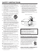
SAFETY INSTRUCTIONS 1 2 3 4 5 6 6A 7 8 9 10 11 12 13 14 15 A. B. C. D. E. 16 17 Read Instructions – All the safety and operating instructions should be read before the unit is operated. Retain Instructions – The safety and operating instructions should be retained for future reference. Heed Warnings – All warnings on the unit and in the operating instructions should be adhered to. Follow Instructions – All operating and other instructions should be followed.
FCC INFORMATION Compliance with FCC regulations does not guarantee that interference will not occur in all installations. If this product is found to be the source of interference, which can be determined by turning the unit “OFF” and “ON”, please try to eliminate the problem by using one of the following measures: 1. IMPORTANT NOTICE : DO NOT MODIFY THIS UNIT! This product, when installed as indicated in the instructions contained in this manual, meets FCC requirements.
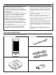
PRECAUTIONS: READ THIS BEFORE OPERATING YOUR UNIT ■ To assure the finest performance, please read this manual carefully. Keep it in a safe place for future reference. STANDBY mode While the power is on, pressing the POWER switch (or the POWER button on the remote control transmitter) switches the unit to the STANDBY mode. (In this mode, the indicator above the POWER switch illuminates.) In this mode, main voltage is still present inside the unit.
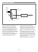
ACTIVE SERVO TECHNOLOGY Highamplitude bass sound Cabinet Air woofer (Helmholtz resonator) Port Active Servo Processing Amplifier Signals Negative-impedance output drive Signals of low amplified Thus it is this problem that is resolved through the employment of a design in which the amplifier functions to supply the signals.
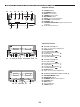
NAMES OF CONTROLS, INDICATORS AND REAR PANEL PARTS CD Player Section 1 2 4 3 7 8 6 5 9 PROGRAM TOTAL REMAIN TIME OVER AUTO EDIT RANDOM A 9 10 8 2 3 6 1 4 5 7 11 12 13 14 15 16 17 18 19 20 OVER REPEAT B 10 11 12 13 14 15 18 19 17 16 20 21 1. 2. 3. 4. 5. 6. 7. 8. 9. 10. 11. 12. 13. 14.
NAMES OF CONTROLS, INDICATORS AND REAR PANEL PARTS Amplifier Section 42 43 44 49 45 46 50 47 42. 43. 44. 45. 46. 47. 48. 49. 50. POWER Switch STANDBY Indicator BASS Tone Control TREBLE Tone Control BALANCE Control INPUT Selector and Indicators VOLUME Control/Indicator PHONES Jack SOUND PROCESSOR Program Selector and Indicators 51. Remote Control Sensor 48 51 Tape Deck Section 52 53 54 55 56 57 58 59 60 61 62 63 64 66 67 68 69 70 71 65 72 E-5 ■ 52. 53. 54. 55. 56. 57. 58.
NAMES OF CONTROLS, INDICATORS AND REAR PANEL PARTS Rear Panel of Tuner/CD Player Section 1. 2. 3. 4. System Control Connector Antenna Terminals RESET Button FREQUENCY STEP Switch (General model only) FREQUENCY STEP switch (General model only) Because the interstation frequency spacing differs in different areas, set the FREQUENCY STEP switch (located at the rear) according to the frequency spacing in your area. Before setting this switch, disconnect the AC supply lead of this unit from the AC outlet. (U.
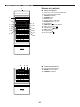
REMOTE CONTROL TRANSMITTER Names of controls 1 1 2 3 4 5 6 7 8 9 0 PROG CLEAR CALL TIME +10 2 3 9 10 4 5 6 7 8 REPEAT CD BAND TUNER 11 b 12 a 13 ■ 1. 2. 3. 4. 5. 6. 7. 8. 9. 10. 11. 12. 13. 14. CD Control Buttons Remote Control Transmitter Window Track Number Input Buttons PROGRAM Button CLEAR Button CALL Button Search Buttons: / REPEAT Button Stop Button: TIME Display Selector Button Open/Close Button: Skip Buttons: / CD Call Button Play Button: Pause Button: ■ 15. 16. 17.
REMOTE CONTROL TRANSMITTER Tape “b” ■ Tape Control Buttons 18. Record/Pause Button: 19. Fast Wind Button: 20. Play Button: 21. Stop Button: 22. Play Button: 23. Fast Wind Button: 24. Fast Wind Button: 25. Play Button: 26. Stop Button: 27. Play Button: 28. Fast Wind Button: 29. TAPE Call Button 19 20 21 22 23 BAND TUNER OFF TAPE 18 Tape “a” b a 28 24 HALL JAZZ CLUB ROCK CNCT 29 25 26 27 REPEAT 30. POWER Switch 31. AUX Call Button 32. DAT Call Button (or PHONO Call Button for U.K.
REMOTE CONTROL TRANSMITTER Loading the batteries for the remote control transmitter 1 2 Remove the battery compartment cover. 3 Replace the battery compartment cover. Insert 2 “AA” size batteries (UM/SUM-3, R6, HP-7 or equivalent) into the battery compartment. * Placing the batteries the wrong way round will cause malfunction. Precautions for battery use Insert the batteries according to the direction indicated in the battery compartment. Replace all batteries with new ones at the same time.
PREPARATION FOR USE Placing the system Tuner/CD player A Left speaker Right speaker Amplifier B Left speaker Notes • If the system is put in a rack, allow a space of a least 3 cm (1-3/16”) above and 10 cm (4”) at the back of the unit. • Disconnect the AC supply lead from the AC outlet before connecting or disconnecting any component. • Be careful not to let the connection cords touch the radiator plates on the rear of the amplifier.
PREPARATION FOR USE Speaker connection Altavoz derecho Connect each speaker wire to the SPEAKERS terminals as shown. (Black wire with white line → plus (+) terminal, black wire → minus (–) terminal) Altavoz izquierdo Cautions • Do not let the bare speaker wires touch each other as this could damage the amplifier and/or speakers. • When connecting the speakers to the unit, be sure to connect the speaker wires properly.
SETTING THE CLOCK 1 1 While the station frequency indicator on the tuner or the “ON TIME” indicator is lit, press the DISPLAY button to display the time. 2 While pressing the TIME ADJUST button, press the HOUR button and set the hour. * Press the HOUR button once to advance the time by 1 hour. Press and hold to advance continuously. 3 While pressing the TIME ADJUST button, press the MINUTE button and set the desired time. * Press the MINUTE button once to advance the time by 1 minute.
COMPACT DISC OPERATION CD playback 2,4 1 2 3 Select the CD position. 4 Press the open/close button to close the disc table. * The total number of tracks and the total playing time will be displayed for several seconds. * The music schedule will be displayed only for the number of tracks on the disc. * If the compact disc contains more than 21 tracks, the “OVER” indicator will light up on the music schedule. 5 Press the open/close button to open the disc table.
COMPACT DISC OPERATION Precautions • If the disc is damaged, dirty or loaded upside down, the display will show error signs as follows: * “no disc” is displayed. * The total track number or “01” is not displayed. Clean, replace or load the disc properly. • If TV or radio interference occurs during CD operation, move the unit away from the TV or radio. • Subjecting the unit to shock or vibration can cause mistracking. • Playing some compact discs at high volume can cause mistracking.
COMPACT DISC OPERATION Skip search 2 The beginning of any track can be found automatically. 1 2 1 2 3 4 5 6 7 8 9 0 PROG CLEAR CALL TIME +10 REPEAT 1 CD BAND TUNER OFF TAPE b a HALL JAZZ CLUB ROCK CNCT POWER AUX DAT - VOLUME Press the button to forward or button to reverse through the CD. * The “ ” indicator flashes while searching for the track beginning.
COMPACT DISC OPERATION Program play You can program up to 20 tracks in any desired order. 2 1 2 3 4 5 6 7 8 9 0 PROG CLEAR CALL TIME +10 3 1 2 Load a disc and close the disc table. 3 Use the track number input buttons to select the desired track number. * The selected track number will be displayed. * The programmed playback order and the total play time of the programmed tracks will be automatically displayed, and only those track numbers will appear in the music schedule.
COMPACT DISC OPERATION Repeat play An entire disc, a single track or a programmed sequence can be continuously repeated. To repeat an entire disc 1 2 3 4 5 6 7 8 9 0 PROG CLEAR CALL TIME +10 2,3 3 1,2 2 REPEAT 1 Press the REPEAT button. * The “REPEAT” indicator will light up. 2 Press the play button. CD BAND TUNER OFF TAPE To repeat a programmed sequence b a HALL JAZZ CLUB ROCK CNCT POWER AUX DAT - VOLUME 1 Program a sequence of up to 20 tracks.
COMPACT DISC OPERATION Random play The tracks on the disc can be played in a random order. 1 2 RANDOM 3 1 2 Load a disc and close the disc table. Press the RANDOM button to begin random play. * The “RANDOM” indicator will light up. * As the tracks to be played are selected, the track numbers “[1]”, “[2]”, “[3]” ... “[20]” in the music schedule will flash on and off and the track number display will change accordingly. To cancel the random play Press the play button. The “RANDOM” indicator goes out.
TUNER OPERATION You can store up to 30 stations (20 FM stations and 10 AM (LW or MW) stations) and recall them together with their FM reception mode (stereo or mono), at the push of a button. 2 3 Auto scan memory By this method, the unit will store stations with strong signals automatically (for FM and AM (LW or MW) respectively).
TUNER OPERATION Manual memory 3,5 When auto scan memory does not function due to a weak signal, frequencies are deviated due to a strong signal, or you want to change the memory contents, perform the following operation. 2 4 1 2 Perform steps 1 – 2 of the “Auto scan memory” section. Use the TUNING ( desired station. or ) button to tune into the Auto tuning When the TUNING ( or ) button is pressed for more than 0.5 second and then released, the tuning stops at the first receivable broadcast station.
TUNER OPERATION 2 4 To recall a memorized station 3 1 2 Select the TUNER position. 3 Press the TUNER PRESET ( or ) button to recall the desired preset station number. The caption FM or AM (LW or MW) and a frequency will appear in the display. 4 To set to FM stereo mode, press the FM MODE button so that the “STEREO” indicator on the display lights up. If the reception is poor, press the FM MODE button so that the “STEREO” indicator goes out.
CASSETTE TAPE OPERATION General information • • • • • • • Detection hole Tab • Do not use C-120 tapes, tapes with internal reels or poorquality tapes, since they can cause malfunctions. Before loading a tape into the cassette compartment, tighten the slack tape with a pen or pencil. Tapes have removable tabs which prevent accidental recording or erasing from taking place. Removing the tab on the top left protects the side facing you from erasure.
CASSETTE TAPE OPERATION Direct playback If a cassette tape is already in the cassette compartment, just press the play button to automatically turn on the power and start playback. Note While the INPUT selector is rotating to select the TAPE position before playback starts, do not press the EJECT button. To stop playback Press the stop button. Note When removing the cassette tape, press the stop and then open the cassette compartment.
CASSETTE TAPE OPERATION Continuous playback 1 1 Load the tapes into the tape “a” and tape “b” cassette compartments. 2 Set the REVERSE MODE switch as desired.
SOUND CONTROL Volume VOLUME Front panel operation Rotate the VOLUME control towards 10 to increase the volume, and towards 0 to decrease the volume. 5 4 6 3 7 - VOLUME + Remote control operation Press the VOLUME + button to increase the volume and the VOLUME – button to decrease the volume. 8 2 I 9 0 10 Balance BALANCE Adjust the balance of the output volume to the left and right speakers to compensate for sound imbalance caused from the speaker settings or the listening room condition.
RECORDING • • • When recording important selections, be sure to make a preliminary test to ensure that the desired material is being properly recorded. The automatic recording level control circuit automatically controls the level of the input signal used for recording. Adjusting the VOLUME, BALANCE, TREBLE and BASS controls and selecting any SOUND PROCESSOR program have no effect on the recorded sound.
RECORDING To exchange a CD for another CD while recording 2 1 Press the stop button of the CD during recording. * The tape stops after about 2 seconds and enters recording standby mode. 2 3 Replace the CD. 4 Press the play button of the CD. * Recording begins after about 2 seconds. 1 4 Choose the selection to be recorded next by using the or button. Note The CD Synchronised Recording System will function even when the CD player is set to the program play or random play mode.
RECORDING 1 7 To edit tracks dividing them to side A and side B automatically (Auto editing function) 8 To use tapes effectively, tracks on a CD are automatically rearranged between side A and side B to best utilize the length of the tape. When the desired tracks are selected in program selection, the tracks stored in memory are automatically divided between side A and side B. 6 4 3 5 1 2 Select the CD position and load the CD to be recorded.
RECORDING To confirm tracks to be recorded and tracks which can not be recorded 1 2 3 4 5 6 7 8 9 0 PROG CLEAR CALL TIME +10 REPEAT Before recording, press the TIME button. The following information will appear on the display by turns whenever the TIME button is pressed.
RECORDING Recording from the built-in tuner 2 4 3 1 5 1 2 3 4 6 7 8 9 0 PROG CLEAR CALL TIME +10 REPEAT 5,1 1 6 1 Tune to the desired station. (Refer to the “TUNER OPERATION” on page 19.) 2 3 Load a tape into the tape “b” cassette compartment. 4 Set the REVERSE MODE switch to to record on only one side, or to for continuous recording on both sides. 5 Press the REC button. * The indicator beside the REC button lights up and the play indicators flash.
HOW TO USE THE BUILT-IN TIMER 6 5 Before setting the timer clock, make sure that the current time is correct. 4 Timer operation To listen to the tuner 1 2 Select the TUNER position. 3 4 Press the DISPLAY button. 5 Release the TIME ADJUST button. * When the start time of the timer is set by mistake, press the CLEAR button and repeat step 4. 6 Press the TIMER button. * “TIMER” appears on the display. This sets the timer to the stand-by condition.
HOW TO USE THE BUILT-IN TIMER To record tuner programs POWER DISPLAY 1 Load a blank cassette tape into the tape “b” cassette compartment. 2 3 Set the TIMER switch to the REC position. Perform steps 1 – 5 of the “To listen to the tuner” section on the previous page. * Recording starts automatically at the desired time. Notes The power will be automatically turned off 2 hours after the timer starts.
HOW TO USE THE BUILT-IN TIMER Sleep timer operation SLEEP This unit can be turned off automatically. Play the desired sound source. Press the SLEEP button repeatedly until the desired sleep time appears in the display. The display will change as described below. (Time is displayed by the minute.) 30 ↑ 45 Current Time ↑ ↑ 60 ↑ ↑ 1 2 15 * The original display mode will resume about 5 seconds after the selection is made. * If the current time is selected, the power is turned off after 2 seconds.
USING EXTERNAL UNITS Auxiliary (AUX) 1 Connect the output lead of a video cassette player, video disc player, etc. to the AUX inputs of this unit. (red → right channel, white → left channel) 2 3 4 Select the AUX position with the INPUT selector. Operate the unit connected to the AUX inputs. Start recording with this unit, if so desired. (See page 30.) Auxiliary (DAT) (U.S.A., Canada and General models) 1 Connect the output lead of a DAT or another input source.
USING EXTERNAL UNITS Headphones • • Be sure that your headphones have a 3.5 mm (1/8”) diameter plug and are between 16 ohms and 50 ohms impedance. Recommended impedance is 32 ohms. When headphones are connected, the speakers are defeated automatically. Adjust the VOLUME control for desired volume. MAINTENANCE Internal care Tape “a” • • Tape “b” Dirty heads, capstans and pinch rollers can cause poor sound and tape jams.
SPECIFICATIONS As a part of policy of continuous improvement, YAMAHA reserves the right to make design and specification changes for product improvement without prior notice. The performance specification figures indicated are nominal values of production units. ■ Tuner/CD player section ■ Amplifier section Power source .................................. AC supplies from amplifier unit Input sensitivity and input impedance ..... AUX; 200 mV/47 kohms Load impedance ..................................
TROUBLESHOOTING If your unit fails to operate normally, check the following points to determine whether the fault can be corrected by the simple measures suggested. If it cannot, or if the fault is not listed in the SYMPTOM column, disconnect the power cord and contact your authorized YAMAHA dealer or service center for help. AMPLIFIER AC supply lead is not plugged in. Plug in AC supply lead. No sound from one speaker Loose speaker connections. Connect properly. No sound from speakers.
YAMAHA YAMAHA YAMAHA YAMAHA YAMAHA YAMAHA YAMAHA ELECTRONICS CORPORATION, USA 6660 ORANGETHORPE AVE., BUENA PARK, CALIF. 90620, U.S.A. CANADA MUSIC LTD. 135 MILNER AVE., SCARBOROUGH, ONTARIO M1S 3R1, CANADA ELECTRONIK EUROPA G.m.b.H. SIEMENSSTR. 22-34, D-25462 RELLINGEN BEI HAMBURG, F.R. OF GERMANY ELECTRONIQUE FRANCE S.A. RUE AMBROISE CROIZAT BP70 CROISSY-BEAUBOURG 77312 MARNE-LA-VALLEE CEDEX02, FRANCE ELECTRONICS (UK) LTD.