AB Integrated Amplifier OWNER’S MANUAL © 2013 Yamaha Corporation Printed in Malaysia ZG15720
A Living Tradition in Sound A piano comes into this world through the perfect synergy of advanced technical skill and artistry. Such a piano can create sound that truly reflects the player’s feelings. The final stage in piano production is called “voicing”. It is here that the instrument is given its soul.
Excellence in Audio Achievement First HiFi System introduced in 1920 We introduced numerous HiFi components (turntables, FM/AM tuners, integrated amplifiers, preamplifiers, power amplifiers and speakers) in 1955 - 1965. Natural Sound Speaker Series introduced in 1967 NS-20 Monitor Speaker CA-1000 Integrated Amplifier Featuring A-Class operation, the CA-1000 set the standard for integrated amplifiers.
◆ Full floating and balanced circuit design achieves the full potential of analogue amplification An entirely new floating and balanced power amplifier achieves complete symmetry and permits full balanced transmission (amplification) from the input jack to just before the speaker jack. ◆ Full-stage balanced signal transmission The integrated amplifier offers full stage balanced transmission, combining high power output with good sound texture and outstanding S/N performance.
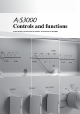
Controls and functions In this chapter, you will learn the controls and functions of A-S3000.
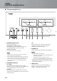
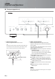
Controls and functions ■ Front panel (pages 6 to 9) LEFT – 60 40 30 0.01 0.1 20 RIGHT 10 3 1 10 50 3 + 0 – 60 40 100 30 0.01 0.1 dB PHONES -6 TRIM SPEAKERS 0 A +6 OFF B 3 1 10 50 TREBLE 3 + 0 100 INPUT BALANCE BAL 2 METER OFF PEAK VU BAL 1 CD LINE 1 A+B BI-WIRING +12 10 dB BASS STANDBY/ON 20 LINE 2 – 1 2 3 4 5 6 1 STANDBY/ON/OFF switch Turns on or off this unit.
VOLUME 3 0 3 + 0 100 INPUT BAL 1 CD PHONO MM TUNER AUDIO MUTE PHONO MC 6 METER selector Switches the display of the meter to OFF, PEAK or VU. OFF: Turns off the meter and the illumination. PEAK: Switches the meter to a peak level meter. The peak level meter shows a momentarily highest audio output level. VU: Switches the meter to a VU (Volume Unit) level meter. The VU level meter shows an effective audio output value that is similar to human senses.
Controls and functions ■ Front panel (pages 6 to 9) RIGHT LEFT – 60 40 30 0.01 0.1 20 10 3 1 10 50 3 + 0 – 60 40 100 30 0.01 0.1 dB PHONES TRIM -6 0 SPEAKERS +6 OFF +12 A TREBLE 3 0 INPUT BAL 2 BAL 1 LINE 1 A+B BI-WIRING TUNER LINE 2 – + – + L A A Remote control sensor Receives signals from the remote control. y The remote control transmits a directional infrared beam.
E AUDIO MUTE indicator Lights when the mute function is turned on with the AUDIO MUTE switch. F VOLUME control Controls the volume level. This does not affect the output level at the LINE 2 REC jacks. VOLUME Note 3 0 3 + The VOLUME control does not affect when you select MAIN DIRECT as the input source. Adjust the volume level using the volume control on the external amplifier connected to the MAIN IN jacks.
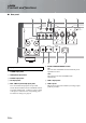
Controls and functions ■ Rear panel 1 3 2 4 5 6 AUTO POWER STANDBY GND PHONO ON BAL 1 TUNER OFF BAL 2 LINE 1 CD NORMAL(EIA) SPEAKERS R CH ATTENUATOR BYPASS ATT. (-6DB) PHASE NORMAL INV. ATTENUATOR BYPASS ATT. (-6DB) PHASE NORMAL INV. +HOT 2 1 3 - COLD SYSTEM CONNECTOR REMOTE IN OUT TRIGGER IN AC IN D E A OR B:4 MIN./SPEAKER A + B:8 MIN.
A SPEAKERS L/R CH terminals 7 8 9 0 AUTO POWER STANDBY ON OFF LINE 2 LINE 1 REC PRE OUT MAIN IN PB NORMAL(EIA) SPEAKERS L CH ASE INV. +HOT 2 1 GND B SYSTEM CONNECTOR Use this connector to connect a product testing device for servicing. C REMOTE IN/OUT jacks Use these jacks to connect an external component for remote control. For details on the connection, see page 21. D TRIGGER IN jack Use this jack to connect an external component for the trigger function.
Controls and functions ■ Remote control 1 1 Infrared signal transmitter Outputs infrared control signals. 2 2 p AMP key Turns this unit ON or switches it to STANDBY mode. For details on STANDBY mode, see “Front panel” (page 6). AMP OPEN/CLOSE 1 CD 2 5 6 BAL 1 3 2 LINE PHONO MAIN DIRECT CD TUNER When LINE 2 is selected as the input source, the audio signals are not output at the LINE 2 REC jacks.
5 p CD key Turns the Yamaha CD player ON or switches it to STANDBY mode. 8 VOLUME +/– keys Control the volume level. Note 6 OPEN/CLOSE key Opens/closes the disc tray of the Yamaha CD player. Refer to the owner’s manual of your CD player for details. Note Some Yamaha CD players do not support the CD key and/or OPEN/CLOSE key of this remote control. The VOLUME keys do not affect when you select MAIN DIRECT as the input source.
Controls and functions ■ Installing batteries in the remote control 1 Remove the battery compartment cover. 2 Insert the two batteries (AAA, R03, UM-4) according to the polarity markings (+ and -) on the inside of the battery compartment. 1 2 3 Reinstall the battery compartment cover.
Connections In this section, you will make connections between A-S3000, speakers, and source components.
Connections Turntable Speakers A (R channel) Ground + - AUTO POWER STANDBY GND PHONO ON TUNER OFF BAL 2 BAL 1 LINE CD NORMAL SPEAKERS R CH ATTENUATOR BYPASS ATT. (-6dB) PHASE NORMAL INV. ATTENUATOR BYPASS ATT. (-6dB) PHASE NORMAL INV. +HOT 2 1 3 - COL SYSTEM CONNECTOR REMOTE IN OUT TRIGGER IN AC IN A OR B:4 MIN./SPEAKER A + B:8 MIN.
Preamplifier, AV receiver, etc. CD recorder, tape deck, etc. External amplifier or active subwoofer Speakers A (L channel) - + AUTO POWER STANDBY ON BAL 1 OFF BAL 2 LINE 2 LINE 1 REC PRE OUT MAIN IN PB NORMAL(EIA) ATOR ATT. (-6DB) PHASE NORMAL INV. ATTENUATOR BYPASS ATT. (-6dB) SPEAKERS L CH PHASE NORMAL INV. +HOT 2 1 GND 3 - COLD AC IN A OR B:4 MIN./SPEAKER A + B:8 MIN./SPEAKER – Network player with XLR jacks + Speakers B (L channel) BD player, etc. Caution Fig.
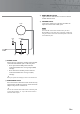
Connections ■ Connecting the speakers ■ Connecting the banana plug (Except for Europe models) 1 Remove approximately 10 mm of insulation from the end of each speaker cable and twist the exposed wires of the cable together to prevent short circuits. First, tighten the knob and then insert the banana plug into the end of the corresponding terminal. 10 mm Banana plug 2 Unscrew the knob and then insert the bare wire into the hole. Hole for banana plug: 5.5 mm dia.
■ Bi-wire connection ■ Connecting the power cable The bi-wire connection separates the woofer from the combined midrange and tweeter section. A bi-wire compatible speaker has four binding post terminals. These two sets of terminals allow the speaker to be split into two independent sections. This split connects the mid and high frequency drivers to one set of terminals and the low frequency driver to the other pair.
Connections ■ Connecting to the BAL 1/BAL 2 jacks Connect your CD player or network player with the XLR balanced output jacks. Set the ATTENUATOR selector and PHASE selector located below the BAL 1 or BAL 2 jacks according to the component to be connected. ATTENUATOR selector: Select the allowable input level for the XLR balanced input jacks. If sound from the connected component is distorted, set the ATTENUATOR selector to ATT. (-6 dB).
■ Operating this unit from another room If you connect an infrared receiver and transmitter to the REMOTE IN/OUT jacks of this unit, you can operate the unit and/or external component using the supplied remote control located in another room. Infrared receiver REMOTE IN OUT When you have another Yamaha component supporting remote connection, as this unit does, an infrared transmitter is not necessary.
Connections ■ Connecting a component supporting the trigger function such as a Yamaha AV receiver The operations of this unit can be controlled in synchronization with the operations of the connected component, such as a Yamaha AV receiver (power ON/ STANDBY or MAIN DIRECT input selection).
Specifications In this section, you will find technical specifications for A-S3000.
Specifications POWER SECTION CONTROL SECTION • Rated Output Power (8 Ω , 20 Hz to 20 kHz, 0.07% THD) .................. 100 W + 100 W (4 Ω , 20 Hz to 20 kHz, 0.07% THD) .................. 150 W + 150 W • Input Sensitivity/Input Impedance CD, etc. ........................................................... 200 mVrms/47 kΩ PHONO MM ................................................... 2.5 mVrms/47 kΩ PHONO MC ...................................................... 100 μVrms/50 Ω MAIN IN ......................
■ Block diagram BAL 1 BAL 2 HOT (+) COLD (-) HOT (+) COLD (-) Phase change (normal / inv.) UNBALANCE CONVERTER COLD (-) HOT (+) BALANCE BALANCE GAIN SEL INPUT SELECTOR MM EQ AMP MC HEAD AMP MM//MC FOR MC AMP VOLUME ATT.UINT1 ATT.UINT2 ATT.UINT3 ATT.UINT1 ATT.UINT2 ATT.
Specifications ■ Tone control characteristics 14 12 10 8 6 Response (dB) 4 2 0 –2 –4 –6 –8 –10 –12 –14 10 20 30 50 100 200 300 500 1k 2k 3k 5k 10k 20k 30k Frequency (Hz) ■ Total harmonic distortion 1.000 0.500 0.200 THD + N Ratio (%) 0.100 0.050 20kHz 0.020 20Hz 0.010 0.005 1kHz 0.002 0.
■ Total harmonic distortion (PHONO) 10 5 3 2 1 THD + N Ratio (%) 0.5 0.3 0.2 0.1 0.05 20Hz 0.03 0.02 1kHz 20kHz 0.01 0.005 0.003 0.002 0.001 0.0005 0.0003 0.0002 0.
Troubleshooting Refer to the chart below if this unit does not function properly. If the problem you are experiencing is not listed below or if the instructions below do not help, turn off this unit, disconnect the power cable, and contact the nearest authorized Yamaha dealer or service center. Problem Cause Remedy See page The power cable is not connected to the AC IN inlet on the rear panel or not plugged in the AC wall outlet. Connect the power cable firmly.
Problem Cause Remedy See page The sound from the component connected to the BAL 1/BAL 2 jacks is degraded. The sound level is higher than the maximum input level for the XLR balanced input jacks. If the output level of the connected component is double, set the ATTENUATOR selector located below the input jacks to ATT. (-6 dB). Bass is not spatial when BAL 1/BAL 2 (balanced input) is selected. The polarity is incorrect. Select the correct polarity with the PHASE selector.
00_Cov_A-S3000_AB.