
Owner's Manual


10 En
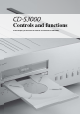
Controls and functions
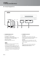
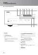
■ Rear panel
1 BALANCED OUT jacks (male)
2 ANALOG OUT jacks
3 DIGITAL IN USB jack (Type B)
4 DIGITAL IN OPTICAL jack
5 DIGITAL IN COAXIAL jack
6 DIGITAL OUT OPTICAL jack
7 DIGITAL OUT COAXIAL jack
While playing the Super Audio CD layer, the audio signals are
output only from the BALANCED OUT and ANALOG OUT
jacks.
8 SYSTEM CONNECTOR
Use this connector to connect a product testing device
for servicing.
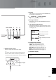
9 REMOTE IN/OUT jacks
Use these jacks to connect an external component for
remote operation.
For details on the connection, see page 21.
0 AC IN inlet
Use this inlet to plug in the supplied power cable.
See page 20 for connection information.
SYSTEM CONNECTOR
REMOTE
IN OUT
BALANCED OUT DIGITAL IN
COAXIAL
DI
OPTICOPTICALUSB
ANALOG OUT BALANCED OUT
GND +HOT
- COLD
2
3
1
AC IN
8
0
3 4 5
9
1 2
See page 18 for connection information.
Note