
User Manual

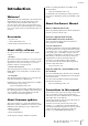


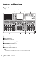
Table Of Contents
- Contents
- PRECAUTIONS
- Introduction
- An overview of the CL series
- Controls and functions
- Touch screen
- Basic operation of the CL series
- Connections
- Setup
- Quick Guide
- Connecting the devices
- Setting the input channels
- Applying EQ/dynamics
- Setting the output channels
- Using GEQ
- Applying effects
- Changing the patch settings
- Grouping and linking
- Setting a custom fader bank
- Using talkback
- Routing the oscillator to an output channel
- Using scene memories
- Recording and playing audio using a USB flash drive
- Saving and loading the unit settings
- Other functions
- Troubleshooting
- Installing the MBCL meter bridge (option)
- Specifications
- Dimensions
- Index
- Block Diagram
- Level Diagram

Controls and functions
Owner’s Manual
10
Controls and functions
Top panel
The top panel of the CL series is divided into the following sections.
1 Channel Strip section ➔ page 11
2 SELECTED CHANNEL section ➔ page 12
3 Display section ➔ page 13
4 Centralogic section ➔ page 13
5 SCENE MEMORY/MONITOR section ➔ page 14
6 USER DEFINED KNOBS section ➔ page 14
7 USER DEFINED KEYS section ➔ page 14
8 Master section ➔ page 15
9 USB connector ➔ page 15
0 Meter section (for CL5 only) ➔ page 15
NOTE
This illustration shows the top panel of the CL5.
The CL3 and CL1 do not feature a Meter section, but enable you to install an optional MBCL meter bridge.
236j
118
5
9
47