
User Manual


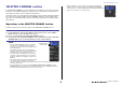

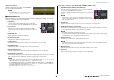
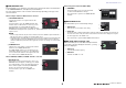

Table Of Contents
- How to Use This Reference Manual
- Contents
- Function Tree
- SELECTED CHANNEL section
- Centralogic section
- Input and output patching
- Input channels
- Signal flow for input channels
- Specifying the channel name/icon
- HA (head amp) settings
- Sending the signal from an input channel to the STEREO/MONO bus
- Added pan function (Monaural input channels only)
- Sending a signal from an input channel to a MIX/ MATRIX bus
- Channel name display indication
- Correcting delay between channels (Input Delay)
- Surround output for input channels
- Channel library operations
- OUTPUT channels
- EQ and Dynamics
- Channel Job
- Scene memory
- Monitor and Cue functions
- Talkback and Oscillator
- Meters
- Graphic EQ, Parametric EQ, Effects, and PREMIUM RACK
- I/O devices and external head amps
- MIDI
- Recorder
- Setup
- About the SETUP screen
- User settings
- Preferences
- USER DEFINED keys
- Functions that can be assigned to USER DEFINED keys
- USER DEFINED knobs
- Functions that can be assigned to USER DEFINED knobs
- Assignable encoders
- Functions that can be assigned to the assignable encoders
- GAIN/PAN/ASSIGN knob (assignable encoder) functions
- Custom fader bank
- Master fader
- Custom fader bank functions
- Console Lock
- Saving and loading setup data to and from a USB flash drive
- Formatting a USB flash drive
- Word clock and slot settings
- Using cascade connections
- Basic settings for MIX buses and MATRIX buses
- Switching the entire phantom power supply on/off
- Specifying the brightness of the touch screen, LEDs, channel name displays, and lamps
- Setting the date and time of the internal clock
- Setting the network address
- Dante audio network settings
- Dante Device Lock
- Support for Dante Domain Manager
- Using GPI (General Purpose Interface)
- Help function
- Other functions
- Initializing the unit to factory default settings
- Adjusting the detection point of the touch screen (Calibration function)
- Adjusting the faders (Calibration function)
- Fine-tuning the input and output gain (Calibration function)
- Adjusting the channel color (Calibration function)
- Adjusting the brightness of the channel name display
- Adjusting the contrast of the channel name display
- Initializing the console settings and Dante audio network settings
- Update procedure for NAME SUB CPU firmware
- Update function to Dante firmware
- Warning/Error Messages
- Index
- Data List
- EQ Library List
- DYNAMICS Library List
- Dynamics Parameters
- Effect Type List
- Effects Parameters
- Premium Rack Processor Parameters
- Parameters That Can Be Assigned to Control Changes
- NRPN Parameter Assignments
- Mixing Parameter Operation Applicability
- MIDI Data Format
- Input/Output Characteristics
- Electrical Characteristics
- Mixer Basic Parameters
- Pin Assignment
- MIDI Implementation Chart

SELECTED CHANNEL section
V5 Reference Manual
8
When using CUE B
Indicates that channels 7 and 8 on the MATRIX
bus are combined with CUE B.
NOTE
For details about how to use CUE B, see the
CUE screen (When configuring CUE B).
GAIN/PATCH field
This field enables you to make HA (head amp) analog or digital gain settings. You can also
view the operational status of the head amp.
1 GAIN knob
Sets the analog gain/digital gain of the head amp.
Press the knob to open the GAIN/PATCH 1ch window.
2 GC indicator
Indicates the fixed gain value output to the audio
network if the Gain Compensation function is turned
on.
3 OVER indicator
Warns you when the signal is clipping.
4 Ø (Phase) indicator
Indicates the status of the phase setting.
5 +48V indicator
Indicates the phantom power (+48V) on or off status for the head amp.
6 HPF ON indicator
Indicates the HPF on/off status of the external head amp.
7 AG-DG LINK indicator
Indicates a link between the analog gain and digital gain of the head amp.
8 Digital/Analog gain value
If analog gain is assigned to the GAIN knob, the digital gain value is shown here. If digital
gain is assigned to the GAIN knob, the analog gain value is shown here.
NOTE
• For an input channel that is patched to an input that has no head amp, 1, 2, 5, 6, and 7
will not be shown. For an output channel,
1 - 7 will not be shown.
• If a GAIN KNOB FUNCTION is set to DIGITAL GAIN in the USER SETUP PREFERENCE
screen, the digital gain knob will appear for
1, and 2, 5, 6, and 7 will not be displayed.
• The display will change depending on the device.
For details, refer to “HA (head amp) settings” (page 32).
If patched to a wireless mic (SELECTED CHANNEL VIEW screen)
1 RX.GAIN knob/TX.GAIN knob/TX.ATT knob
Sets the gain for the transmitter or receiver. Press the knob
to open the GAIN/PATCH 1ch window.
The name of knob will change depending on the connected
device.
NOTE
When remote control connection is disabled for the connected
device, a gray circle is displayed here instead of a knob, and the
gain cannot be adjusted.
2 OL indicator
Lights if the audio signal level of the receiver reaches the overload point.
3 RF (Radio Frequency) signal meter
Shows bars to indicate the level of the RF signal. An active antenna indicator is shown
on the right side. It indicates which antenna is enabled.
NOTE
• The display will change depending on the device.
• For more information about the relationship between the number of bars and the actual strength
of the RF signal, refer to the manual from each developer.
4 Battery indicator
Shows bars to indicate the remaining battery power.
NOTE
For more information about the relationship between the number of bars and maximum operation
time, refer to the manual from each developer.
5 MUTE indicator
Indicates the mute status (on/off) of the audio signal for the receiver.
6 Frequency
Indicates the frequency that is currently set for the RF signal.
41
76
3
5
8
2
1
2
3
6
5
4