
Reference Manual
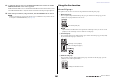
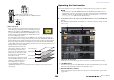
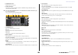

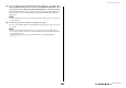
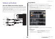
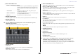

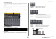
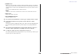
Table Of Contents
- How to Use This Reference Manual
- Contents
- Function Tree
- SELECTED CHANNEL section
- Centralogic section
- Input and output patching
- Input channels
- Signal flow for input channels
- Specifying the channel name, icon and channel color
- Making HA (Head Amp) settings
- Sending a signal from an input channel to the STEREO/MONO buses
- Sending a signal from an input channel to a MIX/ MATRIX bus
- Correcting delay between channels (Input Delay)
- Channel library operations
- Output channels
- EQ and Dynamics
- Grouping and linking
- Scene memory
- About scene memories
- Using scene memories
- Editing scene memories
- Using the Global Paste function
- Using the Focus function
- Using the Recall Safe function
- Using the Fade function
- Outputting a control signal to an external device in tandem with scene recall (GPI OUT)
- Playing back an audio file that links to a scene recall
- Using Preview mode
- Monitor and Cue functions
- Talkback and Oscillator
- Meters
- Graphic EQ, effects, and Premium Rack
- I/O device and external head amp
- MIDI
- User settings (Security)
- Recorder
- Help function
- Other functions
- About the SETUP screen
- Word clock and slot settings
- Using cascade connections
- Basic settings for MIX buses and MATRIX buses
- Switching the entire phantom power supply on/ off
- Specifying the brightness of the touch screen, LEDs, channel name displays, and lamps
- Setting the date and time of the internal clock
- Setting the network address
- Initializing the unit to factory default settings
- Adjusting the detection point of the touch screen (Calibration function)
- Adjusting the faders (Calibration function)
- Fine-tuning the input and output gain (Calibration function)
- Adjusting the channel color (Calibration function)
- Adjusting the brightness of the channel name display
- Adjusting the contrast of the channel name display
- Dante audio network settings
- Using GPI (General Purpose Interface)
- Appendices
- EQ Library List
- DYNAMICS Library List
- Dynamics Parameters
- Effect Type List
- Effects Parameters
- Premium Rack Processor Parameters
- Effects and tempo synchronization
- Parameters that can be assigned to control changes
- NRPN parameter assignments
- Mixing parameter operation applicability
- Functions that can be assigned to USER DEFINED keys
- Functions that can be assigned to USER DEFINED knobs
- Functions that can be assigned to the assignable encoders
- MIDI Data Format
- Warning/Error Messages
- Electrical characteristics
- Mixer Basic Parameters
- M IDI Implementation Chart
- Index

Talkback and Oscillator
Reference Manual
109
4 OSCILLATOR ASSIGN field
An indicator lights to indicate the currently-selected oscillator output destination (input channels
or buses). Use the tabs on the left to select channels or buses to display.
NOTE
In the case of the CL3/CL1, channels that do not exist on those models will not be shown.
5 OSCILLATOR OUTPUT button
Turns the oscillator output on or off.
2. Press the popup button or the ASSIGN field to open the OSCILLATOR popup
window.
In this popup window, you can make detailed settings for the oscillator.
1 OSCILLATOR MODE buttons
Select one of the following three oscillator operating modes:
2 Parameter field
Enables you to set the oscillator parameters. The controllers and their functions in this field vary
depending on the selected mode. You can adjust the values by using the multifunction knobs.
Mode = SINE WAVE
• LEVEL knob.............. Indicates the output level of the sine wave.
• FREQ knob................ Indicates the frequency of the sine wave.
Mode = PINK NOISE
• LEVEL knob.............. Indicates the output level of the pink noise.
• HPF knob................... Indicates the cutoff frequency of the HPF that processes pink noise.
Use the button below the knob to switch the HPF on or off.
• LPF knob.................... Indicates the cutoff frequency of the LPF that processes pink noise.
Use the button below the knob to switch the LPF on or off.
Mode = BURST NOISE
• LEVEL knob, HPF knob, and
LPF knob.................... Same as in PINK NOISE mode.
• WIDTH...................... Indicates the length of noise being output intermittently.
• INTERVAL ................ Indicates the length of silence between noise bursts.
SINE WAVE When the oscillator is turned on, a sine wave will be output continuously.
PINK NOISE When the oscillator is turned on, pink noise will be output continuously.
BURST NOISE When the oscillator is turned on, pink noise will be output intermittently.
21
5
4
3
INTERVAL
WIDTH
Level
Time
Pink noise output
Turn BURST NOISE button is on.