
Reference Manual

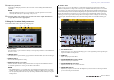
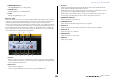
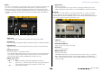

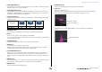
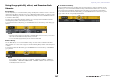

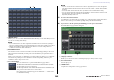

Table Of Contents
- How to Use This Reference Manual
- Contents
- Function Tree
- SELECTED CHANNEL section
- Centralogic section
- Input and output patching
- Input channels
- Signal flow for input channels
- Specifying the channel name, icon and channel color
- Making HA (Head Amp) settings
- Sending a signal from an input channel to the STEREO/MONO buses
- Sending a signal from an input channel to a MIX/ MATRIX bus
- Correcting delay between channels (Input Delay)
- Channel library operations
- Output channels
- EQ and Dynamics
- Grouping and linking
- Scene memory
- About scene memories
- Using scene memories
- Editing scene memories
- Using the Global Paste function
- Using the Focus function
- Using the Recall Safe function
- Using the Fade function
- Outputting a control signal to an external device in tandem with scene recall (GPI OUT)
- Playing back an audio file that links to a scene recall
- Using Preview mode
- Monitor and Cue functions
- Talkback and Oscillator
- Meters
- Graphic EQ, effects, and Premium Rack
- I/O device and external head amp
- MIDI
- User settings (Security)
- Recorder
- Help function
- Other functions
- About the SETUP screen
- Word clock and slot settings
- Using cascade connections
- Basic settings for MIX buses and MATRIX buses
- Switching the entire phantom power supply on/ off
- Specifying the brightness of the touch screen, LEDs, channel name displays, and lamps
- Setting the date and time of the internal clock
- Setting the network address
- Initializing the unit to factory default settings
- Adjusting the detection point of the touch screen (Calibration function)
- Adjusting the faders (Calibration function)
- Fine-tuning the input and output gain (Calibration function)
- Adjusting the channel color (Calibration function)
- Adjusting the brightness of the channel name display
- Adjusting the contrast of the channel name display
- Dante audio network settings
- Using GPI (General Purpose Interface)
- Appendices
- EQ Library List
- DYNAMICS Library List
- Dynamics Parameters
- Effect Type List
- Effects Parameters
- Premium Rack Processor Parameters
- Effects and tempo synchronization
- Parameters that can be assigned to control changes
- NRPN parameter assignments
- Mixing parameter operation applicability
- Functions that can be assigned to USER DEFINED keys
- Functions that can be assigned to USER DEFINED knobs
- Functions that can be assigned to the assignable encoders
- MIDI Data Format
- Warning/Error Messages
- Electrical characteristics
- Mixer Basic Parameters
- M IDI Implementation Chart
- Index

Graphic EQ, effects, and Premium Rack
Reference Manual
131
3. To mount a Premium Rack in the rack, press the RACK MOUNT button for that rack.
The PREMIUM RACK MOUNTER popup window will appear.
4. Use the MODULE SELECT buttons to select the type you want to mount, and press
the OK button.
There are two ways to mount each processor:
• DUAL ..........................The processor is used on two mono channels.
• STEREO......................The processor is used on one stereo channel.
The DUAL button and STEREO button indicate how many rack space units are occupied by the
Premium Rack processor.
The U76 occupies two rack spaces. Other processors occupy one rack space. If you mount a two-
space Premium Rack processor in the rack, you will be unable to mount any more processors
below those rack spaces. Also, you cannot mount a two-space processor in an even-numbered
rack.
5. Press the L side or the A side of the INPUT PATCH button to open the CH SELECT
popup window, and select the insert-out of a channel as the input-source.
For details on the CH SELECT popup window, refer to step 5 of “Virtual rack operations” on
page 115. Insert-out is now assigned to the L input of the processor.
6. Press the L side or the A side of the OUTPUT PATCH button to open the CH SELECT
popup window, and select the insert-in of the same channel as the output-
destination.
For details on the CH SELECT popup window, refer to step 6 of “Virtual rack operations” on
page 115. Insert-in is now assigned to the L output of the processor.
If you are inserting a processor into a channel that handles a stereo source, assign the R channel
insert-out and insert-in to the R input and output of the processor.
7. Use the Bank Select keys in the Centralogic section to access the OVERVIEW screen
for the channel into which you want to insert the processor.
8. Press the INSERT/DIRECT OUT field to access the INSERT/DIRECT OUT popup
window.
Make sure that the rack you inserted in the input and output ports is selected. For details on Insert
Out/In, refer to “Inserting an external device into a channel” on page 21.
9. Turn on the INSERT ON/OFF button for the channel into which you inserted the
processor.
If it is off, press the button to turn it on. In this state, processor insertion is enabled for the
corresponding channel.
10. In the Function Access Area, press the RACK button to access the VIRTUAL RACK
window, and use the PREMIUM tab to display the PREMIUM RACK field.
11. Press the processor rack that you inserted into the channel to open the Premium
Rack popup window.
In this popup window you can edit the processor parameters.