
Reference Manual

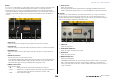

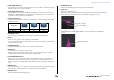
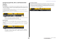

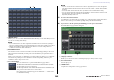

Table Of Contents
- How to Use This Reference Manual
- Contents
- Function Tree
- SELECTED CHANNEL section
- Centralogic section
- Input and output patching
- Input channels
- Signal flow for input channels
- Specifying the channel name, icon and channel color
- Making HA (Head Amp) settings
- Sending a signal from an input channel to the STEREO/MONO buses
- Sending a signal from an input channel to a MIX/ MATRIX bus
- Correcting delay between channels (Input Delay)
- Channel library operations
- Output channels
- EQ and Dynamics
- Grouping and linking
- Scene memory
- About scene memories
- Using scene memories
- Editing scene memories
- Using the Global Paste function
- Using the Focus function
- Using the Recall Safe function
- Using the Fade function
- Outputting a control signal to an external device in tandem with scene recall (GPI OUT)
- Playing back an audio file that links to a scene recall
- Using Preview mode
- Monitor and Cue functions
- Talkback and Oscillator
- Meters
- Graphic EQ, effects, and Premium Rack
- I/O device and external head amp
- MIDI
- User settings (Security)
- Recorder
- Help function
- Other functions
- About the SETUP screen
- Word clock and slot settings
- Using cascade connections
- Basic settings for MIX buses and MATRIX buses
- Switching the entire phantom power supply on/ off
- Specifying the brightness of the touch screen, LEDs, channel name displays, and lamps
- Setting the date and time of the internal clock
- Setting the network address
- Initializing the unit to factory default settings
- Adjusting the detection point of the touch screen (Calibration function)
- Adjusting the faders (Calibration function)
- Fine-tuning the input and output gain (Calibration function)
- Adjusting the channel color (Calibration function)
- Adjusting the brightness of the channel name display
- Adjusting the contrast of the channel name display
- Dante audio network settings
- Using GPI (General Purpose Interface)
- Appendices
- EQ Library List
- DYNAMICS Library List
- Dynamics Parameters
- Effect Type List
- Effects Parameters
- Premium Rack Processor Parameters
- Effects and tempo synchronization
- Parameters that can be assigned to control changes
- NRPN parameter assignments
- Mixing parameter operation applicability
- Functions that can be assigned to USER DEFINED keys
- Functions that can be assigned to USER DEFINED knobs
- Functions that can be assigned to the assignable encoders
- MIDI Data Format
- Warning/Error Messages
- Electrical characteristics
- Mixer Basic Parameters
- M IDI Implementation Chart
- Index

Graphic EQ, effects, and Premium Rack
Reference Manual
134
■ U76
U76 is a processor that emulates a popular vintage compressor used in a wide range of situations. This
processor does not provide the threshold parameter that is found on conventional compressors.
Instead, the intensity of compression is determined by the balance between the input gain and the
output gain. The “All mode” setting for the RATIO parameter allows you to create a heavily-compressed
sound that is typical of this model. It produces an aggressive tonal character with a rich addition of
overtones.
1 INPUT knob
Adjusts the input level. As the input level gets higher, more compression is applied.
2 ATTACK knob
Adjusts the compressor’s attack time. Fully rotate the knob clockwise to set the fastest attack time.
3 RELEASE knob
Adjusts the compressor’s release time. Fully rotate the knob clockwise to set the fastest release
time.
4 RATIO switch buttons
Use these five buttons to set the compression ratio.
A button with the higher number will raise the compression ratio more. Pressing the ALL button
selects All mode, in which the RATIO will become high, and sharp compression with a faster
release time will be applied, creating substantially-distorted aggressive sound.
5 METER switch buttons
Switch the meter display.
• GR.....................Indicates the amount of gain reduction applied by the compressor.
• +4/+8 ................Each meter uses –18 dB as the reference level of the output signal, and indicates
“0VU” for the value of the reference level added by +4 dB or +8 dB.
• OFF...................Turns off the meter display.
6 OUTPUT knob
Adjusts the output level.
If you have adjusted the amount of gain reduction by changing the INPUT level, the level of
audible volume will also change. In this case, use the OUTPUT knob to adjust the volume level.
■ Opt–2A
Opt–2A is a processor that emulates a popular vintage model of tube opto compressors. It features
smooth compression produced using optical components such as a photocell and a light source to
control the level. It also features beautiful high-range overtones created by the warm distortion typical
of tube circuits, resulting in elegant and sophisticated sounds.
1 GAIN knob
Adjusts the output level.
2 PEAK REDUCTION knob
Adjusts the compression amount of the signal.
3 RATIO knob
Adjusts the compression ratio.
4 METER SELECT knob
Switches the meter display.
GAIN REDUCTION indicates the amount of gain reduction when the compressor is operating.
With –18 dB as the reference level of the output signal, the OUTPUT +10 and OUTPUT +4
settings respectively will cause the value +10 dB or +4 dB from this reference level to be shown as
“0VU” on the meter.
21
3645
2134