
Reference Manual
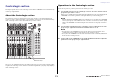
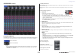

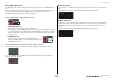
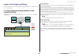
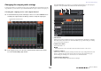
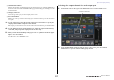
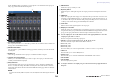
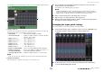
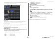
Table Of Contents
- How to Use This Reference Manual
- Contents
- Function Tree
- SELECTED CHANNEL section
- Centralogic section
- Input and output patching
- Input channels
- Signal flow for input channels
- Specifying the channel name, icon and channel color
- Making HA (Head Amp) settings
- Sending a signal from an input channel to the STEREO/MONO buses
- Sending a signal from an input channel to a MIX/ MATRIX bus
- Correcting delay between channels (Input Delay)
- Channel library operations
- Output channels
- EQ and Dynamics
- Grouping and linking
- Scene memory
- About scene memories
- Using scene memories
- Editing scene memories
- Using the Global Paste function
- Using the Focus function
- Using the Recall Safe function
- Using the Fade function
- Outputting a control signal to an external device in tandem with scene recall (GPI OUT)
- Playing back an audio file that links to a scene recall
- Using Preview mode
- Monitor and Cue functions
- Talkback and Oscillator
- Meters
- Graphic EQ, effects, and Premium Rack
- I/O device and external head amp
- MIDI
- User settings (Security)
- Recorder
- Help function
- Other functions
- About the SETUP screen
- Word clock and slot settings
- Using cascade connections
- Basic settings for MIX buses and MATRIX buses
- Switching the entire phantom power supply on/ off
- Specifying the brightness of the touch screen, LEDs, channel name displays, and lamps
- Setting the date and time of the internal clock
- Setting the network address
- Initializing the unit to factory default settings
- Adjusting the detection point of the touch screen (Calibration function)
- Adjusting the faders (Calibration function)
- Fine-tuning the input and output gain (Calibration function)
- Adjusting the channel color (Calibration function)
- Adjusting the brightness of the channel name display
- Adjusting the contrast of the channel name display
- Dante audio network settings
- Using GPI (General Purpose Interface)
- Appendices
- EQ Library List
- DYNAMICS Library List
- Dynamics Parameters
- Effect Type List
- Effects Parameters
- Premium Rack Processor Parameters
- Effects and tempo synchronization
- Parameters that can be assigned to control changes
- NRPN parameter assignments
- Mixing parameter operation applicability
- Functions that can be assigned to USER DEFINED keys
- Functions that can be assigned to USER DEFINED knobs
- Functions that can be assigned to the assignable encoders
- MIDI Data Format
- Warning/Error Messages
- Electrical characteristics
- Mixer Basic Parameters
- M IDI Implementation Chart
- Index

Centralogic section
Reference Manual
14
■ TO STEREO/MONO field
This field displays the on/off status and pan/balance setting of the signal sent to the STEREO/MONO
bus.
If you press this field, the knob will be assigned to the corresponding knob in the Centralogic section.
If you press the field once again, the TO STEREO/MONO 8ch popup window will appear.
This field varies depending on the type of the selected channel.
When an input channel or MIX channel is selected:
1 TO STEREO PAN knob
Sets the pan position of a signal routed to the STEREO bus.
Press the knob to open the STEREO/MONO 8ch popup window. If the ST IN channel is selected,
you can specify whether to view the PAN knob or the BALANCE knob in this window. For a MIX
channel, the PAN knob will appear if the signal is mono, and the BALANCE knob will appear if
the signal is stereo.
2 ST/MONO indicator
Indicates the status of a signal sent to the STEREO/MONO bus.
If an input or MIX channel is set to LCR mode, the LCR indicator will
be displayed in location 2.
When a MATRIX channel (monaural) or MONO channel is selected:
The ΣCLIP indicator appears, indicating that the signal is clipping at some point in the channel.
For a stereo MATRIX channel or STEREO channel, the BALANCE knob appears, indicating the
balance of the left/right channels.
■ DCA group field
A DCA group (1–16) to which the channel is assigned is displayed on the first or second row in this
field.
Press this field to open the DCA/MUTE GROUP ASSIGN MODE popup window.
■ Mute group field
A mute group (1–8) to which the channel is assigned is displayed on the third row in this field. If the
channel has been temporarily removed from the mute group, “S” (Safe) will appear on the third row.
If the dimmer level has been set for a mute group, the color of the characters changes from red to
orange.
Press this field to open the DCA/MUTE GROUP ASSIGN MODE popup window.
1
2
2