
Reference Manual
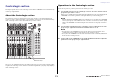
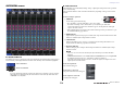

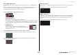
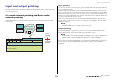
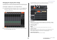
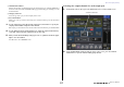
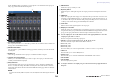
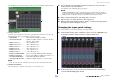
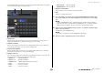
Table Of Contents
- How to Use This Reference Manual
- Contents
- Function Tree
- SELECTED CHANNEL section
- Centralogic section
- Input and output patching
- Input channels
- Signal flow for input channels
- Specifying the channel name, icon and channel color
- Making HA (Head Amp) settings
- Sending a signal from an input channel to the STEREO/MONO buses
- Sending a signal from an input channel to a MIX/ MATRIX bus
- Correcting delay between channels (Input Delay)
- Channel library operations
- Output channels
- EQ and Dynamics
- Grouping and linking
- Scene memory
- About scene memories
- Using scene memories
- Editing scene memories
- Using the Global Paste function
- Using the Focus function
- Using the Recall Safe function
- Using the Fade function
- Outputting a control signal to an external device in tandem with scene recall (GPI OUT)
- Playing back an audio file that links to a scene recall
- Using Preview mode
- Monitor and Cue functions
- Talkback and Oscillator
- Meters
- Graphic EQ, effects, and Premium Rack
- I/O device and external head amp
- MIDI
- User settings (Security)
- Recorder
- Help function
- Other functions
- About the SETUP screen
- Word clock and slot settings
- Using cascade connections
- Basic settings for MIX buses and MATRIX buses
- Switching the entire phantom power supply on/ off
- Specifying the brightness of the touch screen, LEDs, channel name displays, and lamps
- Setting the date and time of the internal clock
- Setting the network address
- Initializing the unit to factory default settings
- Adjusting the detection point of the touch screen (Calibration function)
- Adjusting the faders (Calibration function)
- Fine-tuning the input and output gain (Calibration function)
- Adjusting the channel color (Calibration function)
- Adjusting the brightness of the channel name display
- Adjusting the contrast of the channel name display
- Dante audio network settings
- Using GPI (General Purpose Interface)
- Appendices
- EQ Library List
- DYNAMICS Library List
- Dynamics Parameters
- Effect Type List
- Effects Parameters
- Premium Rack Processor Parameters
- Effects and tempo synchronization
- Parameters that can be assigned to control changes
- NRPN parameter assignments
- Mixing parameter operation applicability
- Functions that can be assigned to USER DEFINED keys
- Functions that can be assigned to USER DEFINED knobs
- Functions that can be assigned to the assignable encoders
- MIDI Data Format
- Warning/Error Messages
- Electrical characteristics
- Mixer Basic Parameters
- M IDI Implementation Chart
- Index

Input and output patching
Reference Manual
18
In the OUTPUT PORT popup window, you can assign the source channel for each output port.
This popup window includes the following items.
1 Slot number/Card type
If an output channel of slot 1–3 is selected for operations, this area indicates the slot number and
the type of I/O card installed in that slot.
2 DELAY SCALE button
Press this button to open the DELAY SCALE popup window, in which you can select the unit for
the delay time.
3 Output port
This is the type and number of the output port to which the channel is assigned.
4 Channel select popup button
Enables you to select the channel that you want to assign to the output port. The name of the
currently-selected channel is displayed.
5 Delay time knob
Sets the delay time of the output port. Press this knob to select it, and then use multifunction
knobs 1–8 to adjust the settings. The millisecond delay time value is indicated above the knob,
and the delay time value in the units selected in the DELAY SCALE popup window is indicated
below the knob.
NOTE
If you have selected ms (millisecond) as the scale, the delay time value will not appear above the
knob.
6 DELAY button
Switches the output port delay on or off.
7 Ø (Phase) button
Switches the phase of the signal assigned to the output port between normal phase and reverse
phase.
8 GAIN knob
Adjusts the output gain of the output port. To adjust this value, press the knob on screen to select
it, and then operate multifunction knobs 1–8. Rotate the knob to set the value in the range of –96
to +24 dB in 1.0 dB steps. Rotate the knob while pressing and holding it down to set the value in
0.1 dB steps. The current value appears immediately below the knob.
9 Level meter
Indicates the level of the signal assigned to the output port.
0 Output port select tabs
Switch the output ports controlled in the popup window in groups of up to eight ports. Tabs are
categorized into three groups: DANTE, SLOT, and PATCH VIEW. To display tabs in the desired
group, press the group name button located at the right or left end of the bottom row.
3. Use the output port select tabs at the bottom of the popup window to select the
output port you want to control.
The tabs correspond to the following output ports.
• DANTE 1–8, 9–16, 17–24, 25–32, 33–40, 41–48, 49–56, 57–64
These tabs control the output channels of the Dante connectors.
• SLOT1 1–8, 9–16
• SLOT2 1–8, 9–16
• SLOT3 1–8, 9–16
These tabs enable you to control output channels 1–8 and 9–16 of slots 1–3 respectively.
• OMNI 1–8
This tab enables you to control OMNI jacks 1–8.
• DIGITAL OUT
This tab enables you to control the L/R channels of the DIGITAL OUT connector.
•PATCH VIEW1
•PATCH VIEW2
These tabs display lists of patches.
4. To assign a channel to an output port, press the channel select popup window for
that port.
2
1
3
4
5
6
7
8
9
0