
Reference Manual
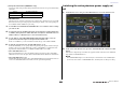


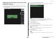
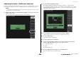

Table Of Contents
- How to Use This Reference Manual
- Contents
- Function Tree
- SELECTED CHANNEL section
- Centralogic section
- Input and output patching
- Input channels
- Signal flow for input channels
- Specifying the channel name, icon and channel color
- Making HA (Head Amp) settings
- Sending a signal from an input channel to the STEREO/MONO buses
- Sending a signal from an input channel to a MIX/ MATRIX bus
- Correcting delay between channels (Input Delay)
- Channel library operations
- Output channels
- EQ and Dynamics
- Grouping and linking
- Scene memory
- About scene memories
- Using scene memories
- Editing scene memories
- Using the Global Paste function
- Using the Focus function
- Using the Recall Safe function
- Using the Fade function
- Outputting a control signal to an external device in tandem with scene recall (GPI OUT)
- Playing back an audio file that links to a scene recall
- Using Preview mode
- Monitor and Cue functions
- Talkback and Oscillator
- Meters
- Graphic EQ, effects, and Premium Rack
- I/O device and external head amp
- MIDI
- User settings (Security)
- Recorder
- Help function
- Other functions
- About the SETUP screen
- Word clock and slot settings
- Using cascade connections
- Basic settings for MIX buses and MATRIX buses
- Switching the entire phantom power supply on/ off
- Specifying the brightness of the touch screen, LEDs, channel name displays, and lamps
- Setting the date and time of the internal clock
- Setting the network address
- Initializing the unit to factory default settings
- Adjusting the detection point of the touch screen (Calibration function)
- Adjusting the faders (Calibration function)
- Fine-tuning the input and output gain (Calibration function)
- Adjusting the channel color (Calibration function)
- Adjusting the brightness of the channel name display
- Adjusting the contrast of the channel name display
- Dante audio network settings
- Using GPI (General Purpose Interface)
- Appendices
- EQ Library List
- DYNAMICS Library List
- Dynamics Parameters
- Effect Type List
- Effects Parameters
- Premium Rack Processor Parameters
- Effects and tempo synchronization
- Parameters that can be assigned to control changes
- NRPN parameter assignments
- Mixing parameter operation applicability
- Functions that can be assigned to USER DEFINED keys
- Functions that can be assigned to USER DEFINED knobs
- Functions that can be assigned to the assignable encoders
- MIDI Data Format
- Warning/Error Messages
- Electrical characteristics
- Mixer Basic Parameters
- M IDI Implementation Chart
- Index

Other functions
Reference Manual
205
Setting the network address
This section explains how to set the network address that will be required when you use the
NETWORK connector on the CL series console to connect it to a computer.
NOTE
Only the Administrator can change network settings.
1. In the Function Access Area, press the SETUP button to access the SETUP screen.
2. In the center of the SETUP screen, press the NETWORK button to access the
NETWORK popup window.
1 IP ADDRESS
Specifies an address that identifies an individual device on the Internet or LAN network.
2 GATEWAY ADDRESS
Specifies an address that identifies a device (gateway) that converts data between different media
or protocols to allow communication within the network.
3 SUBNET MASK
Within the IP address used in the network, this defines the bits that are used for the network
address that distinguishes the network.
4 MAC ADDRESS
Indicates the MAC (Machine Access Control) address, which identifies a host in a network. This
address is for display only, and cannot be edited.
NOTE
The NETWORK connector on the CL series console transmits data via either 100BASE-TX
(transmission speed: maximum 100 Mbps) or 10BASE-T (transmission speed: max 10 Mbps).
3. Press the on-screen knob or the multifunction knobs on the top panel to specify
the address.
If you plan to connect the CL series console to your computer in a one-to-one connection, we
recommend that you use the following default values. Make sure that the IP address and Gateway
address do not match the addresses of any other device on the network.
IP address: 192.168.0.128 or similar
Gateway address: 192.168.0.1 or similar
Subnet mask: 255.255.255.0 or similar
For details on settings related to connecting to a LAN, refer to the CL Editor Installation Guide.
4. When you have finished making settings, press the OK button.
If you changed the setting, a confirmation dialog box will appear.
5. To make the setting, press the OK button.
The changes will be finalized, and the popup screen will close. If you decide to cancel the change,
press the CANCEL button instead of the OK button.
NOTE
In order for the change to take effect, you must power-off the CL series console and then turn it
on again.
6. Restart the CL series console.
1
2
3
4