
Reference Manual


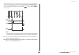
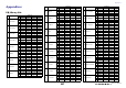
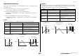
Table Of Contents
- How to Use This Reference Manual
- Contents
- Function Tree
- SELECTED CHANNEL section
- Centralogic section
- Input and output patching
- Input channels
- Signal flow for input channels
- Specifying the channel name, icon and channel color
- Making HA (Head Amp) settings
- Sending a signal from an input channel to the STEREO/MONO buses
- Sending a signal from an input channel to a MIX/ MATRIX bus
- Correcting delay between channels (Input Delay)
- Channel library operations
- Output channels
- EQ and Dynamics
- Grouping and linking
- Scene memory
- About scene memories
- Using scene memories
- Editing scene memories
- Using the Global Paste function
- Using the Focus function
- Using the Recall Safe function
- Using the Fade function
- Outputting a control signal to an external device in tandem with scene recall (GPI OUT)
- Playing back an audio file that links to a scene recall
- Using Preview mode
- Monitor and Cue functions
- Talkback and Oscillator
- Meters
- Graphic EQ, effects, and Premium Rack
- I/O device and external head amp
- MIDI
- User settings (Security)
- Recorder
- Help function
- Other functions
- About the SETUP screen
- Word clock and slot settings
- Using cascade connections
- Basic settings for MIX buses and MATRIX buses
- Switching the entire phantom power supply on/ off
- Specifying the brightness of the touch screen, LEDs, channel name displays, and lamps
- Setting the date and time of the internal clock
- Setting the network address
- Initializing the unit to factory default settings
- Adjusting the detection point of the touch screen (Calibration function)
- Adjusting the faders (Calibration function)
- Fine-tuning the input and output gain (Calibration function)
- Adjusting the channel color (Calibration function)
- Adjusting the brightness of the channel name display
- Adjusting the contrast of the channel name display
- Dante audio network settings
- Using GPI (General Purpose Interface)
- Appendices
- EQ Library List
- DYNAMICS Library List
- Dynamics Parameters
- Effect Type List
- Effects Parameters
- Premium Rack Processor Parameters
- Effects and tempo synchronization
- Parameters that can be assigned to control changes
- NRPN parameter assignments
- Mixing parameter operation applicability
- Functions that can be assigned to USER DEFINED keys
- Functions that can be assigned to USER DEFINED knobs
- Functions that can be assigned to the assignable encoders
- MIDI Data Format
- Warning/Error Messages
- Electrical characteristics
- Mixer Basic Parameters
- M IDI Implementation Chart
- Index

Other functions
Reference Manual
224
3 GPI OUT SETUP popup button
Press this button to open the GPI OUT SETUP popup window.
The button shows the name of the currently selected function or parameter.
4 TEST button
While this is on, the corresponding GPI OUT port will be active and will output a control signal.
5. Specify the POLARITY MODE for each port.
For each port, select either low-active or high-active as appropriate for the specifications of the
external device you’re using.
6. To assign a function or parameter, press the GPI OUT SETUP popup button.
You can assign the following functions.
7. In each field, select the desired function or parameter.
8. When you have finished making settings, press the OK button.
9. Repeat steps 5 through 8 to specify functions and parameters for other ports.
Using FADER START
Make FADER START settings if you want a device connected to a GPI OUT port to operate in tandem
with fader operations.
1. Connect an external device to the CL series console’s GPI connector.
2. In the function access area, press the SETUP button to access the SETUP screen.
3. Press the MIDI/GPI button.
The MIDI/GPI screen will appear.
Function Parameter CL console operation
NO ASSIGN --- No assignment
CUE ACTIVE
CUE ON Turn on the [CUE] key of the selected channel
DCA ONLY Turn on the DCA [CUE] key
INPUT ONLY Turn on the [CUE] key of an input channel
OUTPUT ONLY Turn on the [CUE] key of an output channel
GPI IN ACTIVE IND. PORT 1–PORT 5
The function assigned to GPI IN port 1–5
becomes active
POWER ON --- The power of the CL series console is turned on
USER DEF.
KEY ACTIVE IND.
USER DEFINED KEY 1–
USER DEFINED KEY 16
The function assigned to the USER DEFINED
key becomes active