
Reference Manual

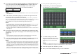
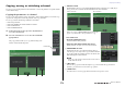


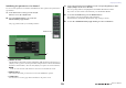
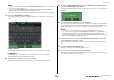
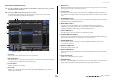

Table Of Contents
- How to Use This Reference Manual
- Contents
- Function Tree
- SELECTED CHANNEL section
- Centralogic section
- Input and output patching
- Input channels
- Signal flow for input channels
- Specifying the channel name, icon and channel color
- Making HA (Head Amp) settings
- Sending a signal from an input channel to the STEREO/MONO buses
- Sending a signal from an input channel to a MIX/ MATRIX bus
- Correcting delay between channels (Input Delay)
- Channel library operations
- Output channels
- EQ and Dynamics
- Grouping and linking
- Scene memory
- About scene memories
- Using scene memories
- Editing scene memories
- Using the Global Paste function
- Using the Focus function
- Using the Recall Safe function
- Using the Fade function
- Outputting a control signal to an external device in tandem with scene recall (GPI OUT)
- Playing back an audio file that links to a scene recall
- Using Preview mode
- Monitor and Cue functions
- Talkback and Oscillator
- Meters
- Graphic EQ, effects, and Premium Rack
- I/O device and external head amp
- MIDI
- User settings (Security)
- Recorder
- Help function
- Other functions
- About the SETUP screen
- Word clock and slot settings
- Using cascade connections
- Basic settings for MIX buses and MATRIX buses
- Switching the entire phantom power supply on/ off
- Specifying the brightness of the touch screen, LEDs, channel name displays, and lamps
- Setting the date and time of the internal clock
- Setting the network address
- Initializing the unit to factory default settings
- Adjusting the detection point of the touch screen (Calibration function)
- Adjusting the faders (Calibration function)
- Fine-tuning the input and output gain (Calibration function)
- Adjusting the channel color (Calibration function)
- Adjusting the brightness of the channel name display
- Adjusting the contrast of the channel name display
- Dante audio network settings
- Using GPI (General Purpose Interface)
- Appendices
- EQ Library List
- DYNAMICS Library List
- Dynamics Parameters
- Effect Type List
- Effects Parameters
- Premium Rack Processor Parameters
- Effects and tempo synchronization
- Parameters that can be assigned to control changes
- NRPN parameter assignments
- Mixing parameter operation applicability
- Functions that can be assigned to USER DEFINED keys
- Functions that can be assigned to USER DEFINED knobs
- Functions that can be assigned to the assignable encoders
- MIDI Data Format
- Warning/Error Messages
- Electrical characteristics
- Mixer Basic Parameters
- M IDI Implementation Chart
- Index

Grouping and linking
Reference Manual
72
4. If you turned on the MIX ON, MIX SEND, MATRIX ON, or MATRIX SEND buttons in
step 3, use the buttons in the SEND PARAMETER field to specify the bus(es) for
which you want operations to be linked (multiple selections are allowed).
The table below lists the buttons you can select in the SEND PARAMETER field.
NOTE
If nothing is selected in the SEND PARAMETER field, the send on/off and send level parameters
will not be linked.
5. To link channels, hold down the [SEL] key for the link-source input channel and
press the [SEL] key for the link-destination channel.
At this time, the values of the parameters you selected in steps 3 and 4 will be copied from the
link-source to the link-destination channel. Subsequent operations of the parameters you selected
in steps 3 and 4 will be linked between channels that belong to the same link group.
The current link status is displayed in the channel display field of the window.
NOTE
• If you want to link three or more channels, hold down the link-source [SEL] key and successively
press the [SEL] key for each channel you want to add to the link group.
• When you press the [SEL] key for a channel (that belongs to a link group) to make it light, the
[SEL] keys of all channels that belong to the same link group will blink.
• If you link an input channel to a ST IN channel, parameters that do not exist for a ST IN channel
will be ignored.
6. If you want to add a new channel to an existing link group, hold down any [SEL]
key within the group and press the [SEL] key for the channel that you want to add
to the group.
NOTE
If the link-destination channel is already assigned to another link group, the channel will be
removed from the previous group and added to the newly assigned group.
7. To remove a channel from a link group, hold down any [SEL] key in the same link
group, and press the [SEL] key for the channel that you want to remove.
NOTE
You can also remove all linked channels from the same link group temporarily. This can be helpful
if you want to edit parameters that are linked to each other while maintaining the same relative
level differences. For example, this may be the case for parameters such as the HA analog gain
and fader, or if you want to change the level balance between channels that belong to the same
link group. While pressing and holding down the [SEL] key for the desired linked channel, adjust
the parameter value.
While you are holding down the [SEL] key, the HA analog gain and fader values will not be linked.
(However, you cannot temporarily cancel this link during the “fading” phase of a recalled scene.)
You can also perform the operations from step 5 on screen.
5. To link channels, press the channel display field.
The CH LINK SET popup window will appear.
6. Select a channel that you want to link.
7. To confirm the link, press the LINK
button in the lower left of the screen.
An alphabetical character that indicates the link
group will appear on the selected channel
button.
NOTE
If you use CL5 settings data on the CL3/CL1, or CL3 settings data on the CL1, buttons will be
shown crossed-out if they are assigned to a channel that does not exist on that model.
8. In the same way, link other channels as you wish.
9. When you have finished linking channels, press the CLOSE button.
MIX 1–24 MIX buses 1–24
MATRIX 1–8 MATRIX buses 1–8