
User Manual


Quick Guide
MG206C-USB/MG166CX-USB/MG166C-USB Owner’s Manual
Mixer Basics
8
3
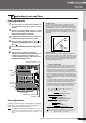
Connecting Microphones and/or Instru-
ments.
For details on making connections refer to the “Setup”
section on page 15 and the “Front & Rear Panels” sec-
tion on page 16.
To prevent loud pops and noises, turn on the
power to your sound gear starting with the
sources (instruments, CD players, etc.) and end-
ing with the power amplifier or powered speakers.
Example : Instruments, microphones, and CD players first, then
the mixer, and finally the power amplifier or powered
speakers.
Observe the following precautions when
turning on phantom power.
• Make sure that the PHANTOM switch is off when
phantom power is not needed.
• When turning the switch on, be sure that only con-
denser microphones are connected to the XLR input
jacks. Other devices may be damaged if connected
to phantom power. This precaution does not apply to
balanced dynamic microphones, however, as these
will not be affected by phantom power.
•To minimize the possibility of speaker damage, turn
phantom power on ONLY while your power amplifier
or powered speakers are switched off. It’s also a
good idea to turn the mixer’s output controls—STE-
REO OUT Master fader , GROUP 1-2 fader and
GROUP 3-4 fader—all the way down.
•We recommend that you set the computer output to the
maximum level and mute the computer’s internal
speaker. For details on how to make the setting refer to
the “The recorded sound is too low in level.” in the “Trou-
bleshooting” on page 24.
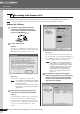
• The first time you connect to the computer’s USB con-
nector, or change the connection to a different USB port,
a driver installation display may appear after turning the
power to the MG mixer on. If this occurs, wait until the
installation is complete before proceeding.
DI
USB cable
Be sure to turn the MG mixer
PHANTOM switch on when
using phantom-powered con-
denser microphones.
Although electric guitars
and basses can be con-
nected directly to the
mixer’s inputs, the sound is
likely to be thin and possi-
bly noisy. For best results
with these types of instru-
ments use a DI box (direct
box) or amp simulator
between the instrument
and the mixer.
Step
3
Powering Up the System
CAUTION
NOTE
Balanced, Unbalanced—What’s the Difference?
In a word: “noise.” The whole point of balanced lines is noise
rejection, and it’s something they’re very good at. Any length of
wire will act as an antenna to pick up the random electromag-
netic radiation we’re constantly surrounded by: radio and TV sig-
nals as well as spurious electromagnetic noise generated by
power lines, motors, electric appliances, computer monitors, and
a variety of other sources. The longer the wire, the more noise it
is likely to pick up.
That’s why balanced lines are the best choice for long cable runs.
If your “studio” is basically confined to your desktop and all con-
nections are no more than a meter or two in length, then unbal-
anced lines are fine—unless you’re surrounded by extremely
high levels of electromagnetic noise. Another place balanced
lines are almost always used is in microphone cables. The rea-
son for this is that the output signal from most microphones is
very small, so even a tiny amount of noise will be relatively large,
and will be amplified to an alarming degree in the mixer’s high-
gain head amplifier.
Noise
Hot (+)
Cold (–)
Ground
Source
Cable
Noise cancelled
Noise-free
signal
Phase
inversion
Receiving device
Phase
inversion
Balanced noise cancellation
Cable Guidelines
Microphone cable Balanced is best.
Short line-level cables
Unbalanced cable is fine in a rela-
tively noise-free environment.
Long line-level cables Balanced is best.