Synthesizer Parameter Manual EN Introduction This manual explains the parameters and technical terms that are used for synthesizers incorporating the Yamaha AWM2 sound generators. You should use this manual together with the documentation unique to the product. Read the documentation first and use this parameter manual to learn more about parameters and terms that relate to Yamaha synthesizers. We hope that this manual gives you a detailed and comprehensive understanding of Yamaha synthesizers.
Table Of Contents 1 Voice Parameters . . . . . . . . . . . . . . . . . . . . . . . . . . . . . . . . . . . . . . . 4 1-1 1-2 1-3 2 Basic Terms . . . . . . . . . . . . . . . . . . . . . . . . . . . . . . . . . . . . . . . . . . . . 4 1-1-1 Definitions . . . . . . . . . . . . . . . . . . . . . . . . . . . . . . . . . . . . . . . . 4 Synthesis Parameters . . . . . . . . . . . . . . . . . . . . . . . . . . . . . . . . . . . . . 5 1-2-1 Oscillator . . . . . . . . . . . . . . . . . . . . . . . . . . . . . . .
2-3-5 2-3-6 2-3-7 2-3-8 2-3-9 2-3-10 2-3-11 2-3-12 2-3-13 2-3-14 2-3-15 2-3-16 2-3-17 2-3-18 2-3-19 3 E .............................................. F .............................................. G .............................................. H .............................................. I ............................................... L .............................................. M .............................................. N .............................................. O .............
Voice Parameters 1 Voice Parameters 1-1 Basic Terms 1-1-1 Definitions Voice A Voice is a musical instrument sound that is built into an Electronic Musical Instrument. There are two Voice Types: Normal Voices Drum Voices Normal Voice Normal Voices are mainly pitched musical instrument-type sounds. You can play over the range of the keyboard at the standard pitch for each key. Normal Voices consist of one or more Elements (see "Element").
Voice Parameters 1-2 Synthesis Parameters 1-2-1 Oscillator An Oscillator outputs the waveform that determines the basic pitch of an Element and is one unit of the tone generator block of the Electronic Musical Instrument. You can: Assign the waveform (or basic sound material) to each Element of a Normal Voice or each key of a Drum Voice; Set the note range for the Element (Normal Voice); Set the Velocity response (Normal Voice); Set the XA (eXpanded Articulation) parameters.
Voice Parameters Waveform Bank Specifies the Waveform Bank of an Element or Drum Key (Drum Voice). Preset User: This lets you create User Waveforms based on samples that are recorded in the Sampling mode. Waveform Category and Number Specifies the waveform of an Element (Normal Voice) or Drum Key (Drum Voice). The waveform is specified as a combination of a Waveform Category and a Waveform Number. Assign Mode (for Drum Voices) Enables or disables double playback of the same note.
Voice Parameters Velocity Limit Determines the minimum and maximum Velocity values in which an Element responds. Each Element will only sound for notes played between its specified Velocity Limits. For example, this lets you have one Element sound when you play softly and have a different one sound when you play strongly. If you first specify the maximum value and then the minimum value, for example "93 to 34," then the Velocity range covers both "1 to 34" and "93 to 127.
Voice Parameters 1-2-2 Pitch The processing unit that controls the pitch of the wave output from the Oscillator on the tone generator block of the Electronic Musical Instrument. This unit controls the pitch of the sound (wave) output from the Oscillator. In the case of a Normal Voice, you can detune separate Elements, apply Pitch Scaling and so on. Also, by setting the Pitch Envelope Generator (Pitch EG), you can control how the pitch changes over time.
Voice Parameters Pitch Key Follow Sensitivity Center Key Determines the central note or pitch for Pitch Key Follow. The note number set here is the same pitch as normal regardless of the Pitch Key Follow setting.
Voice Parameters C: D: E: F: G: H: I: J: K: L: M: N: Time Pitch Hold Time Attack Time Decay 1 Time Decay 2 Time Release Time Hold Level Attack Level Decay 1 Level Decay 2 Level = Sustain Level Release Level Hold Time Determines the time between the moment you press a key on the keyboard and the moment the envelope starts to rise. Attack Time Determines the speed of attack from the initial pitch (Hold Level) to the normal pitch of the Voice after the hold time has elapsed.
Voice Parameters EG Depth Velocity Sensitivity Determines how the pitch range of the Element responds to Velocity. Positive values: High Velocities cause the pitch range to expand and low Velocities cause it to contract, as shown in Figure 4. Negative values: High Velocities cause the pitch range to contract and low Velocities cause it to expand. 0: The pitch envelope does not change, regardless of the Velocity.
Voice Parameters EG Time Velocity Sensitivity Determines how the Pitch EG transition time (speed) responds to Velocity, or to the strength with which the key is pressed. Positive values: High Velocities result in a fast Pitch EG transition speed while low Velocities result in a slow speed, as shown in Figure 7. Negative values: High Velocities result in a slow Pitch EG transition speed while low Velocities result in a fast speed.
Voice Parameters EG Time Key Follow Sensitivity Center Key Determines the central note or pitch for the EG Time Key Follow. When the Center Key note is played, the Pitch EG behaves according to its actual settings.
Voice Parameters Cutoff Velocity Sensitivity Determines how the Cutoff Frequency responds to Velocity, or the strength with which you play notes. Positive values: The Cutoff Frequency rises the stronger you play the keyboard. Negative values: The Cutoff Frequency rises the softer you play the keyboard. 0: The Cutoff Frequency does not change, regardless of the Velocity. Resonance Resonance is used to set the amount of Resonance (harmonic emphasis) applied to the signal at the Cutoff Frequency.
Voice Parameters Cutoff Key Follow Center Key This indicates the central note for Cutoff Key Follow. E D F G + – A B C Figure 10: Cutoff Key Follow and Center Key A: B: C: D: E: F: G: Lower range Center Key = C3 Higher range Amount of Cutoff Frequency change When Cutoff Key Follow Sensitivity = 100 Large Small Distance Determines the Distance between the two Cutoff Frequencies of the Dual Filter Types (which consist of two identical filters in parallel), and of the LPF12+BPF6 type.
Voice Parameters 1-2-5 Filter Type LPF (Low-Pass Filter) This is a Filter Type that only passes signals below the Cutoff Frequency. The sound can be brightened by raising the Cutoff Frequency of the filter. On the other hand, the sound can be darkened by lowering the Cutoff Frequency of the filter. You can produce a distinctive "peaky" sound by raising the Resonance to boost the signal level in the area of the Cutoff Frequency.
Voice Parameters LPF24D A dynamic -24 dB/oct Low-Pass Filter with a characteristic digital sound. Compared to the LPF24A type, this filter can produce a more pronounced Resonance effect. A B Figure 12: LPF24D A: B: Resonance Frequencies that are “passed” by the filter LPF24A A digital dynamic Low-Pass Filter with characteristics similar to a 4-pole analog synthesizer filter. LPF18 3-pole -18 dB/oct Low-Pass Filter. LPF18s 3-pole -18 dB/oct Low-Pass Filter.
Voice Parameters HPF24D A dynamic -24 dB/oct High-Pass Filter with a characteristic digital sound. This filter can produce a pronounced Resonance effect. A Figure 14: HPF24D A: Resonance HPF12 -12 dB/oct dynamic High-Pass Filter. BPF (Band-Pass Filter) A Filter Type that only passes a band of signals around the Cutoff Frequency.
Voice Parameters BPF12D The combination of a -12 dB/oct HPF and LPF with a characteristic digital sound. Y A B B D X C Figure 16: BPF12D A: B: C: D: X: Y: BPF6 Resonance Cutoff Range Frequencies that are “passed” by the filter -12 dB/oct Frequency Level The combination of a -6 dB/oct HPF and LPF.
Voice Parameters BPFw A -12 dB/oct BPF that combines HPF and LPF filters to allow wider bandwidth settings. Y B B A X C Figure 18: BPFw A: B: C: X: Y: Width can be increased Cutoff Range Frequencies that are “passed” by the filter Frequency Level BEF (Band-Eliminate The Band-Eliminate Filter has an opposite effect on the sound compared Filter) to the Band-Pass Filter. When this Filter Type is selected, you can set the Cutoff Frequency around which the audio signal is muted or eliminated.
Voice Parameters Dual LPF Two -12 dB/oct Low-Pass Filters connected in parallel. You can edit the distance between the two Cutoff Frequencies. A Y X B Figure 20: Dual Low-Pass Filters A: B: X: Y: Distance Lower Cutoff Frequency is set directly on the Display Frequency Level Dual HPF Two -12 dB/oct High-Pass Filters connected in parallel. Dual BPF Two -6 dB/oct Band-Pass Filters connected in parallel. Dual BEF Two -6 dB/oct Band-Eliminate Filters connected in serial.
Voice Parameters LPF12+BPF6 A combination of a -12 dB/oct Low-Pass Filter and a -6 dB/oct Band-Pass Filter connected in parallel. You can edit the distance between the two Cutoff Frequencies. Y A X B Figure 22: LPF12+BPF6 A: B: X: Y: 1-2-6 Distance Lower Cutoff Frequency is set directly on the Display Frequency Level Filter EG (Envelope Generator) This lets you control the transition in tone from the moment the sound starts to the moment the sound stops.
Voice Parameters M: Decay 2 Level = Sustain Level N: Release Level Hold Time Determines the time between the moment you press a key on the keyboard and the moment the envelope starts to rise. Attack Time Determines the speed of attack from the initial Cutoff Frequency (at Hold Level) to the maximum level of the Voice after the Hold Time has elapsed.
Voice Parameters EG Depth Velocity Sensitivity Determines how the range of the Cutoff Frequency responds to Velocity. Positive values: high Velocities cause the Filter EG range to expand and low Velocities cause it to contract, as shown in Figure 24 and Figure 25. Negative values: High Velocities cause the Filter EG range to contract and low Velocities cause it to expand. 0: The Filter EG range does not change, regardless of the Velocity.
Voice Parameters EG Time Velocity Sensitivity Determines how the Filter EG transition time (speed) responds to Velocity, or the strength with which the key is pressed. Positive values: High Velocities result in a fast Filter EG transition speed while low Velocities result in a slow speed, as shown in Figure 27 and Figure 28. Negative values: High Velocities result in a slow Filter EG transition speed while low Velocities result in a fast speed.
Voice Parameters EG Time Key Follow Sensitivity Center Key Determines the central note or pitch for EG Time Key Follow. When the Center Key note is played, the Filter EG behaves according to its actual settings.
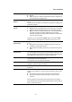
Voice Parameters Y 81 74 68 60 A B C D X Figure 30: Filter Scale A: B: C: D: X: Y: 1-2-8 Break Point 1 Break Point 2 Break Point 3 Break Point 4 Note Cutoff Frequency Break Point 1 - 4 Determines the four Filter Scale Break Points by specifying their respective note numbers. Offset 1 - 4 Determines the offset value of the Cutoff Frequency of each Filter Scale Break Point. Amplitude The Amplitude unit controls the output level (amplitude or volume) of the sound output from the Filter.
Voice Parameters Level Velocity Sensitivity Offset Raises or lowers the level specified by the Level Velocity Sensitivity. If the result is higher than 127, the velocity is set to 127.
Voice Parameters Level Velocity Sensitivity Curve Determines how the actual Velocity will be generated according to the Velocity (strength) with which you play notes on the keyboard.
Voice Parameters Level Key Follow Sensitivity Center Key This indicates that the central note for Level Key Follow Sensitivity is C3. E D F G + – A B C Figure 35: Level Key Follow and Center Key A: B: C: D: E: F: G: Lower range Center Key = C3 Higher range Amount of Amplitude EG level change When Level Key Follow = 100 Large Small Pan Adjusts the stereo pan position of the sound.
Voice Parameters 1-2-9 Amplitude EG (Envelope Generator) This lets you control the transition in Amplitude from the moment the sound starts until the moment the sound stops. You can create a custom Amplitude EG by setting parameters as illustrated below. When you press a key on the keyboard, the volume will change according to these EG settings.
Voice Parameters Half Damper Switch Determines if the Half Damper is switched on. When the Half Damper Switch is set to On, holding down the FC3 Foot Controller produces a "half-pedal" effect just as on a real acoustic piano. Half Damper Time Determines how quickly the sound decays to silence after the key is released while holding down the Foot Controller FC3 with the Half Damper Switch set to On.
Voice Parameters EG Time Key Follow Sensitivity Center Key Determines the central note for EG Time Key Follow Sensitivity. When the Center Key note is played, the AEG behaves according to its actual settings.
Voice Parameters 97 Y 90 84 76 A B C D X Figure 40: Amplitude Scale A: B: C: D: X: Y: Break Point 1 Break Point 2 Break Point 3 Break Point 4 Note Amplitude Break Point 1 - 4 Determines the four Amplitude Scale Break Points by specifying their respective note numbers. Offset 1 - 4 Determines the offset value of the level of each Amplitude Scale Break Point.
Voice Parameters Phase Determines the starting phase point for the LFO Wave when it is reset. Y X 90 0 A 180 270 240 120 Figure 41: Phases of a wave A: X: Y: Phase Time Level Tempo Sync Determines whether or not the LFO speed is synchronized to the tempo of the Arpeggio or sequencer (Song or Pattern). Tempo Speed This parameter allows you to make detailed note value settings that determine how the LFO pulses in sync with the Arpeggio or sequencer.
Voice Parameters Each-on: The LFO resets with each note you play and starts a waveform at the phase specified by the Phase parameter. X A B Figure 43: Key On Reset Each-on A: Key On (first note) B: Key On (second note) X: Time 1st-on: The LFO resets with each note you play and starts a waveform at the phase specified by the Phase parameter.
Voice Parameters Fade-In Time Determines the amount of time for the LFO effect to fade in after the Delay time has elapsed. A higher value results in a slower fade-in. 0: The LFO effect will not fade in but reach the maximum level immediately after the Delay time has elapsed.
Voice Parameters Hold (Hold Time) Determines the time during which the LFO is held at its maximum level. A higher value results in a longer Hold Time. 127: No fade-out.
Voice Parameters Fade-Out Time Determines the amount of time for the LFO effect to fade out (after the Hold Time has elapsed). A higher value results in a slower fade-out. C D B X A Figure 48: Lower value: faster fade-out C B D X A Figure 49: Higher value: slower fade-out A: B: C: D: X: Key On Maximum Hold Fade-Out Time Pitch Modulation Depth Determines the amount (depth) by which the LFO Wave varies (modulates) the pitch of the sound. The higher the setting, the greater the depth of control.
Voice Parameters Control Depth Determines the LFO Wave Depth. LFO Element Switch Determines whether or not each Element is to be affected by the LFO. Depth Offset Determines the offset values of the Control Depth parameter for the respective Elements. If the resultant Control Depth value is negative, it will be set to 0. If the resultant Control Depth value is greater than 127, it will be set to 127. LFO Phase Offset Determines the offset values of the Phase parameter for the respective Elements.
Voice Parameters 1-3 Operational Parameters 1-3-1 General Voice Bank The Voice Bank is the memory that includes data of Normal Voices and Drum Voices. Category The keyword Category indicates the instrument characteristics or the type of sound. A Preset Voice is registered to a certain Category. Assignable Function Determines whether the buttons ASSIGNABLE FUNCTION [1] and ASSIGNABLE FUNCTION [2] function as latch type or as momentary type.
Voice Parameters Mono/Poly Selects monophonic or polyphonic. Mono: The selected Voice is played back monophonically; only a single note is played back simultaneously. Poly: The selected Voice is played back polyphonically; multiple notes or chords can be played back simultaneously. For many instrument sounds (such as bass and synth lead), Mono allows a more natural and smooth sounding legato performance than Poly.
Voice Parameters 1-3-4 Micro Tuning List Equal Temperament The "compromise" tuning used for most of the last 200 years of Western music, and found on most electronic keyboards. Each half step is exactly 1/12 of an octave, and music can be played in any key with equal ease. However, none of the intervals are perfectly in tune. Pure Major This tuning is designed so that most of the intervals (especially the major third and perfect fifth) in the major scale are pure.
Voice Parameters 1-3-5 Arpeggio This function lets you automatically trigger musical and rhythmic phrases using the current Voice by simply pressing a key or keys on the keyboard. The Arpeggio sequence changes in response to the actual notes or chords you play, giving you a wide variety of inspiring musical phrases and ideas, both in composing and performing. Arpeggio Bank Determines the Arpeggio Bank containing the desired Arpeggio type. Preset Bank: Selects the preset Arpeggio Type.
Voice Parameters Key Mode Determines how the Arpeggio plays back when playing the keyboard. Sort: When you play specific notes (for example, the notes of a chord), the same sequence plays, no matter what order you play the notes. Thru: When you play specific notes (for example, the notes of a chord), the resulting sequence differs depending on the order of the notes. Direct: Note events of the Arpeggio sequence do not play; only the notes you play on the keyboard are heard.
Voice Parameters Velocity Rate Determines how much the Velocity of Arpeggio playback is offset from the original value. 100%: The original Velocities are used. Below 100%: Reduces the Velocities of the Arpeggio notes. Above 100%: Increases the Velocities. If the resulting Velocity value is 0, it will be set to 1. If the resulting Velocity value is greater than 127 it will be set to 127.
Voice Parameters Random SFX Velocity Offset Determines the offset value by which the Random SFX notes will be shifted from their original Velocities. If the resulting Velocity is 0, it will be set to 1. If the resulting Velocity is greater than 127, it will be set to 127. Random SFX Key On Defines the way in which the Velocity of the Random SFX special sound Control is determined. On: The Random SFX special sound is played with a preprogrammed Velocity.
Voice Parameters 1-3-7 Effect The Effect unit applies Effects to the output of the tone generator block and audio input block, processing and enhancing the sound. Effects are applied in the final stages of editing, letting you change the sound of the created Voice as desired. The unprocessed sound is called "dry" sound, and the processed sound is referred to as "wet." Master Effect Master effects are applied to the final stereo output signal of the entire sound.
Voice Parameters Insertion Effect Connection Lets you set the effect routing for Insertion Effects A and B. Parallel: Signals processed with the Insertion Effect A and B blocks are sent to the Master Effect, Master EQ, Reverb and Chorus blocks.
Voice Parameters 1-3-8 Chorus to Reverb Determines the Send level of the signal sent from the Chorus Effect to the Reverb Effect. The higher the value, the deeper the Reverb that is applied to the Chorus processed signal. Reverb Return Determines the Return level of the Reverb Effect. Chorus Return Determines the Return level of the Chorus Effect. Reverb Pan Determines the pan position of the Reverb effect sound. Chorus Pan Determines the pan position of the Chorus effect sound.
Voice Parameters Q A parameter that determines the EQ bandwidth, or range of frequencies, to be attenuated/boosted. Consequently, this parameter determines the frequency characteristic curve. The Q setting is only available for the Mid band, which is a Peaking type EQ. The EQ Shape of the High and Low band is of the Shelving type.
Effects 2 Effects 2-1 Basic Terms 2-1-1 Definisions VCM (Virtual Circuitry Modelling) VCM is a technology that authentically models the elements in analog circuitry (such as resistors and capacitors). Effect types using the VCM technology produce the uniquely warm characteristics of vintage processing gear. REV-X REV-X is a Reverb algorithm developed by Yamaha.
Effects 2-2-3 TEMPO DELAY MONO Tempo-synchronized Mono delay. TEMPO DELAY STEREO Tempo-synchronized Stereo delay. CONTROL DELAY Delay with delay time that is controllable in real time. DELAY LR Produces two delayed sounds: L and R. DELAY LCR Produces three delayed sounds: L, R and C (center). DELAY LR (Stereo) Produces two delayed sounds in stereo: L and R.
Effects 2-2-6 Tremolo & Rotary The Tremolo effect cyclically modulates the volume. The Rotary Speaker effect simulates the characteristic vibrato effect of a rotary speaker. 2-2-7 AUTO PAN An effect which cyclically moves the sound left/right and front/back. TREMOLO An effect which cyclically modulates the volume. ROTARY SPEAKER Simulation of a rotary speaker. Distortion This type can be used mainly for guitar, adding distortion with an edge to the sound.
Effects 2-2-10 Lo-Fi This Effect intentionally degrades the audio quality of the input signal via several methods such as lowering the sampling frequency. LO-FI Degrades the audio quality of the input signal to get a lo-fi sound. NOISY Adds noise to the current sound. DIGITAL TURNTABLE Simulates the noise of an analog record. 2-2-11 Tech This Effect changes the tonal characteristics radically by using a filter and modulation.
Effects 2-3 Effect Parameters 2-3-1 A 2-3-2 2-3-3 AEG Phase Offsets the phase of the Amplitude EG. AM Depth Determines the depth of Amplitude Modulation. AM Inverse R Determines the phase of the Amplitude Modulation for the R channel. AM Speed Determines the Amplitude Modulation speed. AM Wave Selects the wave for modulating the Amplitude. AMP Type Selects the amplifier type to be simulated. Analog Feel Adds the characteristics of an analog flanger to the sound.
Effects Comp Output Level Control Type Determines the level of the signal output from the compressor effect. This is a parameter of Control Delay. Normal: The delay effect is always applied to the sound. Scratch: The delay effect is not applied if both the Delay Time and Delay Time Offset are set to 0.
Effects 2-3-5 Divide Type Determines how the sound (wave) is sliced by the note length. Drive Determines the extent of a series of specific effects. For the distortion, noisy or slice effects, this parameter determines the extent to which the sound is distorted. For one of the Miscellaneous effects, this parameter determines the extent to which the enhancer or talking modulator is applied. Drive Horn Determines the depth of the modulation generated via the rotation of the horn.
Effects EQ2 Q Determines the EQ2 bandwidth, or range of EQ2 frequencies. EQ3 Frequency Determines the center frequency of the EQ3. EQ3 Gain Determines the level gain of the EQ3 center frequency. EQ3 Q Determines the EQ3 bandwidth, or range of EQ3 frequencies. EQ4 Frequency Determines the center frequency of the EQ4. EQ4 Gain Determines the level gain of the EQ4 center frequency. EQ4 Q Determines the EQ4 bandwidth, or range of EQ4 frequencies.
Effects 2-3-7 G Gate Switch Determines whether or not the microphone sound is output from the HPF while you release the keys. Off: The microphone sound is always output. On: The microphone sound is output only while a key is pressed. Normally, set this parameter to On. Gate Time 2-3-8 2-3-9 Determines the gate time of the sliced portion. H Height Determines the height of the simulated room. Hi Resonance Adjusts the Resonance of the high frequencies.
Effects Input Select Selects an input channel. Inst Input Level Determines the level of the keyboard performance sound which is to be input to the Vocoder. 2-3-10 L L/R Depth Determines the depth of the L/R pan effect. L/R Diffusion Determines the spread of the sound. Lag Determines the lag time that is additionally applied to the delayed sound specified via a note length. LFO Depth Determines a specific value, depending on the selected Effect type.
Effects 2-3-11 M Manual Determines a specific value, depending on the selected Effect type. For VCM Flanger, this parameter determines the offset value of the delay modulation. For VCM Phaser mono and VCM Phaser stereo, this parameter determines the offset value of the phase modulation. Meter Changes the meter. Mic Gate Threshold Determines the threshold level of the noise gate for the microphone sound.
Effects 2-3-12 N Noise Gate Attack Determines the amount of time that elapses between the playing of a key and the start of the Noise Gate effect. Noise Gate Release Determines the amount of time that elapses between the releasing of a note and the end of the Noise Gate effect. Noise Gate Threshold Determines the minimum input level at which the Noise Gate effect is applied. Noise Input Level Determines the noise level which is to be input. Noise Level Determines the noise level.
Effects Pedal Control When VCM Pedal Wah is selected, this parameter determines the Cutoff Frequency of the wah filter. For best results, assign this parameter to the Foot Controller in the Controller Set display, then use the Foot Controller to control this parameter. Pedal Response Determines how the sound responds to changes in the damper control. Phase Shift Offset Determines the offset value of the phase modulation.
Effects Slow-Fast Time of Horn Determines how long it takes for the rotation speed of the horn to change from the current speed (slow or fast) to the other one (fast or slow) when the rotation speed is switched. Slow-Fast Time of Rotor Determines how long it takes for the rotation speed of the rotor to change from the current speed (slow or fast) to another one (fast or slow) when the rotation speed is switched. Space Type Selects the type of space simulation.
MIDI 3 MIDI 3-1 Overview 3-1-1 About MIDI MIDI (Musical Instrument Digital Interface) is a standard that allows electronic musical instruments to communicate with each other, by sending and receiving compatible types of MIDI data or messages. The types of MIDI data include Note, Control Change, Program Change and various other types. This synthesizer can control other MIDI devices by transmitting note-related data and various types of controller data.
MIDI A B C Figure 57: MIDI Cable A: MIDI Transmit channel 2 B: MIDI cable C: MIDI Receive channel 2 3-1-3 MIDI ports The above-mentioned sixteen-channel limit can be overcome by using separate MIDI "ports," each supporting sixteen channels. While a single MIDI cable is equipped to handle data over up to sixteen channels simultaneously, a USB connection is capable of handling far more, thanks to the use of MIDI ports.
MIDI 3-2 Channel Messages 3-2-1 Note On/Off Messages which are generated when the keyboard is played: Note On: Generated when a key is pressed. Note Off: Generated when a key is released. Each message includes a specific note number, which corresponds to the key that is pressed, plus a Velocity value based on how hard the key is struck.
MIDI Portamento Time (Control #5) Messages that control the duration of portamento, or a continuous pitch glide between successively played notes. 127: Maximum portamento time. 0: Minimum portamento time. When the parameter Portamento Switch (Control #65) is set to On, the value set here can adjust the speed of the pitch change. These parameters specify the value of RPN MSB and RPN LSB events. Data Entry MSB (Control #6) and Data The parameter value is determined by combining the MSB and LSB.
MIDI Harmonic Content (Control #71) Messages that adjust the filter Resonance set for each part. The value set here is an offset value which will be added to or subtracted from the Voice data. Release Time (Control #72) Messages that adjust the Amplitude EG Release Time set for each part. This is an offset that is added to or subtracted from the Voice data. Attack Time (Control Messages that adjust the Amplitude EG Attack Time set for each part.
MIDI Table 3: RPN Parameter List RPN 3-2-5 Parameter Name Data Entry (Range) MSB Function MSB LSB LSB 000 000 Pitch Bend Sensitivity 000 - 024 - Specifies the amount of pitch bend produced in response to pitch bend data in semitone increments. 000 001 Fine Tune -64 - +63 - Adjusts the tuning in cent increments. 000 002 Coarse Tune -24 - +24 - Adjusts the tuning in semitone increments.
MIDI 3-3 System Messages 3-3-1 System Exclusive Messages Changes internal tone generator settings such as Voice and effect settings, remote switch control, tone generator more switching, and others via MIDI. The Device Number of the synthesizer must match the Device Number of the external MIDI device when transmitting/receiving bulk data, parameter changes or other System Exclusive Messages.
MIDI Stop (FCH) This message causes MIDI sequence data (song) to stop playing back. This message will be transmitted when pressing the [] (Stop) button during playback. Active Sensing (FEH) This is a type of MIDI message used to prevent unexpected results when a MIDI cable is disconnected or damaged while the instrument is being played.
Yamaha Web Site (English only) http://www.yamahasynth.com Yamaha Manual Library http://www.yamaha.co.jp/manual/ U.R.G.