Owner’s Manual EN
SPECIAL MESSAGE SECTION PRODUCT SAFETY MARKINGS: Yamaha electronic products may have either labels similar to the graphics shown below or molded/stamped facsimiles of these graphics on the enclosure. The explanation of these graphics appears on this page. Please observe all cautions indicated on this page and those indicated in the safety instruction section. CAUTION RISK OF ELECTRIC SHOCK DO NOT OPEN CAUTION: TO REDUCE THE RISK OF ELECTRIC SHOCK. DO NOT REMOVE COVER (OR BACK).
FCC INFORMATION (U.S.A.) 1. IMPORTANT NOTICE: DO NOT MODIFY THIS UNIT! This product, when installed as indicated in the instructions contained in this manual, meets FCC requirements. Modifications not expressly approved by Yamaha may void your authority, granted by the FCC, to use the product. 2. IMPORTANT: When connecting this product to accessories and/or another product use only high quality shielded cables. Cable/s supplied with this product MUST be used. Follow all installation instructions.
Explanation of Graphical Symbols The lightning flash with arrowhead symbol within an equilateral triangle is intended to alert the user to the presence of uninsulated “dangerous voltage” within the product’s enclosure that may be of sufficient magnitude to constitute a risk of electric shock to persons. CAUTION RISK OF ELECTRIC SHOCK DO NOT OPEN CAUTION: TO REDUCE THE RISK OF ELECTRIC SHOCK, DO NOT REMOVE COVER (OR BACK). NO USER-SERVICEABLE PARTS INSIDE. REFER SERVICING TO QUALIFIED SERVICE PERSONNEL.
PRECAUTIONS PLEASE READ CAREFULLY BEFORE PROCEEDING Please keep this manual in a safe and handy place for future reference. WARNING Always follow the basic precautions listed below to avoid the possibility of serious injury or even death from electrical shock, short-circuiting, damages, fire or other hazards. These precautions include, but are not limited to, the following: Power supply/Power cord If you notice any abnormality • Do not place the power cord near heat sources such as heaters or radiators.
CAUTION Always follow the basic precautions listed below to avoid the possibility of physical injury to you or others, or damage to the instrument or other property. These precautions include, but are not limited to, the following: Power supply/Power cord Connections • Do not connect the instrument to an electrical outlet using a multiple-connector. Doing so can result in lower sound quality, or possibly cause overheating in the outlet.
NOTICE Information To avoid the possibility of malfunction/ damage to the product, damage to data, or damage to other property, follow the notices below. About copyrights Handling • Do not use the instrument in the vicinity of a TV, radio, stereo equipment, mobile phone, or other electric devices. Otherwise, the instrument, TV, or radio may generate noise.
Welcome Thank you for purchasing the Yamaha CP88 or CP73. This instrument is a Stage Piano designed especially for live performance. Please read this Owner’s Manual carefully before using the instrument in order to take full advantage of its various features. When you have finished reading the manual, keep it in a safe, accessible place, and refer to it when you need to better understand an operation or function.
Contents PRECAUTIONS ..................................................................5 NOTICE ...............................................................................7 Information..........................................................................7 Welcome...............................................................................8 Accessories ...........................................................................8 Main Features .........................................................
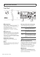
Controls and Functions Front Panel 2 3 5 4 1 6 7 8 9 ) Live Set (page 12) Piano section (page 14) 1 Pitch bend lever Settings of LCD and the indicator lamp Use this controller to smoothly raise or lower the pitch of played notes. When you release it, the lever will automatically spring back to the original position, and the pitch will return to normal. The range can be set for each sections from the [SETTINGS] button → “Controllers” → “Bend Range” (page 36).
Controls and Functions Illustration shows the CP88. The keyboard range of the CP88 is A-1 to C7, the keyboard range of CP73 is E1 to E7. Electric Piano section (page 15) Sub section (page 16) Delay section (page 17) Reverb section (page 17) Master EQ (page 17) 7 [PANEL LOCK] button 9 [TOUCH] button Use this button to switch the panel lock function on and off. When this is set to “On,” control panel operations are disabled, ensuring that settings cannot be inadvertently changed.
Controls and Functions Live Set Live Set View @ # $ % ^ Displays a Live Set Page (Live Set Sound [1] – [8]) in a single screen, for convenient overall view of the available sounds. To open the Live Set View, turn the Encoder dial when at the Top screen. The will appear on the left of the currently selected Live Set Sound. To change the Live Set Sound in Live Set View, turn the Encoder dial to select a Live Set Sound, and press the [ENTER] button to return to the Top screen.
Controls and Functions NOTE If you wish to store the currently edited settings to another Live Set Sound, use the Encoder dial to select the Live Set Sound which is to be the store destination. Press the keyboard to confirm that the sound has been changed to the edited settings. Copying a Live Set Sound 1. Select the Live Set Sound you wish to copy. 2. Call up the Copy screen. [MENU] button → “Job” → “Live Set Manager”→ “Copy.
Controls and Functions ( Voice select switch Piano section Use this switch to select one of the Voices of the category selected with the Voice category selector. For information about the Voices, refer to page 39. A * A Voice number display ( B Displays the currently selected Voice numbers. H C F D I Press these buttons to alternate between the keyboardsplit settings of each Voice section. The area for which the indicator lamp is lit will sound.
Controls and Functions Effect Description Effect Description Distortion Monaural compressor plus distortion. Settings from the left-most to the center of the [DEPTH] knob applies compression. Turning the [DEPTH] knob from the center to right (clockwise) increases the amount of distortion. T.Wah Wah responds to keyboard dynamics. Turn the [DEPTH] knob to adjust the effect strength, and turn the [RATE] knob to adjust the effect amount. P.
Controls and Functions T [DEPTH] knob Sub section Use this knob to adjust the depth of the selected effect. * a [SPEED] knob A Q Use this knob to adjust the modulation speed of the selected effect. R Effect ( B C T E D a S G & Q [ATTACK] knob Use this knob to adjust the attack time. The CP88 and CP73 feature insertion effects and delay/ reverb effects that can be configured for each Voice section, as well as a master EQ that affects all the Voice sections in the same way.
Controls and Functions When all the indicator lamps of the Voice sections are lit, the send levels from each Voice section can be adjusted equally. When the send levels of each Voice section are set individually, the indicator lamp of the [DEPTH] knob is unlit. However, when the send levels are readjusted, the indicator lamp of the [DEPTH] knob light, and the send levels are changed from the previously set value.
Controls and Functions Rear Panel 1 2 4 3 5 AC outlet USB flash drive 1 [STANDBY/ON] switch 6 MIDI [IN]/[OUT] terminals For switching the instrument to standby or turning it on. With a standard MIDI cable (available separately), you can connect an external MIDI instrument, and control it from this instrument. Likewise, you can use an external MIDI device (such as a keyboard or sequencer) to control the sounds on this instrument. 2 [AC IN] jack For connecting the supplied AC power cord.
Controls and Functions 6 7 8 9 ) ! @ # 3 FC3A, FC4A, FC4A, FC5 FC5 External MIDI keyboard, etc. External synthesizer, etc. FC7 Headphones Mixer, etc. Keyboard amplifier or Monitor speakers 9 FOOT CONTROLLER [1]/[2] jacks # [PHONES] jack Use these jacks to connect a separately sold foot controller (FC7) in order to continuously control one of various different assignable functions by foot, such as volume and the tone of Voice sections.
Setting Up Power Supply Connect the ends supplied AC power cord in the following order. Make sure the [STANDBY/ON] switch on the instrument is set to the STANDBY position. 1. Connect the supplied power cord to the [AC IN] jack on the instrument’s rear panel. 2. Connect the other end of the power cord to an AC outlet. Connecting Speakers or Headphones Since the instrument has no built-in speakers, you will need to monitor the sound of the instrument by using external equipment.
Basic Structure & Display Content Auto Power Off Function The Auto Power Off function automatically turns off this instrument after 30 minutes of inactivity. By default, this is set to “Disable.” Setting the Auto Power Off function [MENU] button → “General” → “Auto Power Off ” → “Enable” (page 30). NOTICE • Since any unsaved data will be lost when the Auto Power Off function turns off this instrument. Make sure to store your work before this occurs.
Basic Structure & Display Content Editing File Names/Live Set Sound Names Editing File Names See “Saving the settings to a USB flash drive” on page 23. Editing Live Set Sound Names Select the desired Live Set Sound for which you wish to edit the name → [SETTINGS] button → “Name” → Edit the name → [STORE] button → [ENTER] button. NOTE The edited names will not be stored in this instrument unless you perform the Store operation with the [STORE] button.
Saving / Loading Data Saving / Loading Data In the File screens ([MENU] button → “File”) you can transfer entire system settings and data (such as Live Sets and Live Set Sounds) between this instrument and an external USB flash drive connected to the USB [TO DEVICE] terminal. This section explains how to save/load the data to/from the user memory of this instrument. Saving the settings to a USB flash drive Loading the settings from a USB flash drive 1.
Precautions when using the USB [TO DEVICE] terminal This instrument features a built-in USB [TO DEVICE] terminal. When connecting a USB device to the terminal, be sure to handle the USB device with care. Follow the important precautions below. NOTE For more information about the handling of USB devices, refer to the owner’s manual of the USB device. Compatible USB devices Only USB memory devices of the flash drive variety can be used with this instrument.
Using with Other MIDI Devices Using with Other MIDI Devices By using standard MIDI cables (sold separately), you can connect other MIDI devices such as synthesizers and sound modules to this instrument via its MIDI [IN]/[OUT] terminals. This type of connection allows you to exchange MIDI data with these devices. The MIDI [IN]/[OUT] terminals and the USB [TO HOST] terminal can be used for MIDI data transmission/reception. The illustrations below show examples of how to use the MIDI [IN]/[OUT] terminals.
Using with a Computer Port 2 This port is used as the MIDI Thru Port, allowing you to re-transmit MIDI data received by this instrument to an external MIDI device. When you use this port, set “MIDI” to “Off ” and “USB” to “On” from the [MENU] button → “General” → “MIDI Settings” → “MIDI Port.” The MIDI data received via the USB [TO HOST] terminal will be re-transmitted to an external MIDI device via the MIDI [OUT] terminal.
Using with a Computer Precautions when using the USB [TO HOST] terminal When connecting the computer to the USB [TO HOST] terminal, make sure to observe the following points. Failing to do so risks freezing the computer and corrupting or losing the data. If the computer or the instrument freezes, restart the application software or the computer OS, or turn the power to the instrument off and then on again. NOTICE • Use an AB type USB cable. Do not use a USB 3.0 cable.
MENU LIST From the [MENU] button, you can configure various parameters and functions over the whole system of this instrument. The settings will be stored in this instrument. Operation 1. Press the [MENU] button. 2. Use the Encoder dial and the [ENTER] button to call up the item you wish to edit. 3. Use the Encoder dial to change the value or settings. 4. Press the [ENTER] button to execute the settings. The display will return to the Top screen.
MENU LIST Function name MIDI Settings Description MIDI Control MIDI Control = On Control change messages from the enabled controls of this instrument can be transmitted or received. NOTE Since the control lights will be lit according to the settings of “Display Lights” (page 30), even when the Voice section [ON/OFF] switches or the Insertion effect [ON/OFF] buttons are set to OFF, the control change messages will be transmitted or received.
MENU LIST Function name Keyboard/ Pedal Description Sustain Pedal Type Determines which type of foot switch connected to the FOOT SWITCH [SUSTAIN] jack is recognized. Select “FC3A (HalfOn)” when you wish to use half-damper playing techniques. Settings: FC3A (HalfOn), FC3A (HalfOff), FC4A/FC5 Default: FC3A (HalfOn) Foot Switch Assign Determines the Control Change number generated by using the Footswitch connected to the FOOT SWITCH [ASSIGNABLE] jack.
MENU LIST Function name Display Lights Description LCD SW Determines whether to show (On) or not show (Off) the Top screen. The various setting screens such as the MENU screens and the SETTINGS screens are always shown regardless of this setting. Default: On LCD Contrast Adjusts the contrast of this instrument’s LCD.
MENU LIST Function name Section Manager Description Copy Paste Piano Copies the settings of the currently selected Piano section. E.Piano Copies the settings of the currently selected Electric piano section. Sub Copies the settings of the currently selected Sub section. Piano Pastes the settings of the previously copied Voice section. This function cannot be executed when no Voice section has been previously copied or when a different Voice section is selected as the paste destination. E.
SETTINGS LIST From the [SETTINGS] button, you can configure and store the various settings of the currently selected Live Set Sound. The settings will be stored in this instrument. Operation 1. Press the [SETTINGS] button. 2. Use the Encoder dial and the [ENTER] button to call up the item you wish to edit. 3. Use the Encoder dial to change the value or settings. 4. Press the [ENTER] button to execute the settings. The display will return to the Top screen.
SETTINGS LIST Function name Description Mode SW Switches the Master Keyboard Mode settings. When “On” is selected, the Master Keyboard Mode is enabled, and the indication appears on the Live Set screen. Default: Off Advanced Zone SW Switches the setting range of Master Keyboard Mode. When “On” is selected, you can make detailed settings. Default: Off NOTE When “Off” is selected, the detailed settings will not be displayed.
SETTINGS LIST Function name Zone Settings Description Tx SW Program* Determines whether to enable (On) or disable (Off) the sending of MIDI Program Change messages to the external instrument corresponding to the currently selected zone. Default: On Tx SW Volume* Determines whether to enable (On) or disable (Off) the sending of MIDI Volume messages to the external instrument corresponding to the currently selected zone.
SETTINGS LIST Controllers Function name Bend Range Description Piano Determines the maximum Pitch Bend Range in semitones for each Voice section. E.Piano Settings: -24 – +0 – +24 Default: +2 Sub P.Mod Depth Piano Determines the depth of vibrato effect on keyboard sound. This can be set individually for each Voice section. E.Piano Settings: 0 – 127 Piano/E.
DATA LIST Live Set Sound List No 1 1 Natural CFX G2 1 2 NaturalImperial G2 1 3 Jazz S700 G2 1 4 Rock Upright G2 1 5 Simple 78 G2 1 6 Funky Tines G2 1 7 Tremolo Wr G2 1 8 Clavi B Amped G2 2 1 CFX+DX Legend G2 2 2 A.Bass/78Rd G2 2 3 80s El Grand G2 2 4 Brite Pop 8ve G2 2 5 E.
DATA LIST 38 Name Split Section Point BANK No 6 5 Clavi Wah Dist G2 6 6 Squeeze B G2 6 7 Long Chorus S G2 6 8 Rock Wr w/Ba G2 7 1 CP80 Comp G2 7 2 Natural CP80 G2 7 3 Chorus Legend G2 7 4 Chorus FTine G2 7 5 Chorus 7II G2 7 6 Legend + Pad G2 7 7 SynBass/DXEP G2 7 8 Digi DX Pads G2 8 1 Bright Bars G2 8 2 All Bars Out G2 8 3 PipeOrgan1 G2 8 4 PipeOrgan2 G2 8 5 The Red Combo G2 8 6 Italian Combo G2 8 7 Aggro Syn Pad G2 8 8 RdBa
DATA LIST Voice List Section PIANO Category Grand Piano CFX 2 Imperial 3 S700 Digi Piano Upright Piano 5 U1 6 SU7 CP 7 CP80 1 8 CP80 2 Rd Wr Clv DX SUB Voice 1 4 Special Piano E.PIANO No. Pad/Strings Organ Chromatic Perc.
DATA LIST P:=Piano, E:=Electric Piano, S:=Sub Parameters shown within parentheses do not affect the sound of this instrument. Only affected by foot switch, and not foot controller.
DATA LIST LCD indication PEDAL Panel controls Table* D 101 (RPN MSB) 102 P: SW & Voice section [ON/OFF] switch B 103 P: Split B SPLIT [L R] button E 100Hz 104 P: Octave C OCTAVE [-2 -1]/[+1 +2] buttons F 105 P: Effect Type H Insertion effect switch button 106 E: SW 107 108 109 Controller Parameter Transmitted Recognized 14 0-3 0-3 110Hz 15 4-6 4-6 G 125Hz 16 7-9 7-9 & Voice section [ON/OFF] switch B 140Hz 17 10-12 10-12 E: Split B SPLIT [L R] button E 160Hz
DATA LIST H N Controller Parameter Transmitted Recognized A.Pan 0 0 0-21 Trem 1 25 22-42 R.Mod 2 50 43-63 T.Wah 3 76 64-85 P.
DATA LIST MIDI Musical Instrument Digital Interface (MIDI) is a global standard designed to allow performance, Voice, and other data to be transferred between musical instruments. As such, reliable data communication is assured even between musical instruments and equipment from different manufacturers. In addition to data generated by playing the keyboard or selecting a Live Set Sound, a wide range of other data types—such as tempo and instrument controls—can also be exchanged via MIDI.
DATA LIST MIDI Data Format (1) TRANSMIT FLOW MIDI <-+--[SW1]--+---------NOTE OFF 8nH OUT | | +---------NOTE ON 9nH | | | +---------CONTROL CHANGE | | MODULATION BnH,01H | | SUSTAIN SWITCH BnH,40H | | ASSIGNABLE CONTROLLER BnH,(01H...76H) | | | | Refer to Correspondence Table of Control | | Change Number List (page 41) for the | | Control Change when the MIDI Control is | | set to “On.
DATA LIST (3-2) CHANNEL MODE MESSAGES STATUS CONTROL NUMBER CONTROL VALUE 1011nnnn(BnH) 0ccccccc 0vvvvvvv when the Byte Count, Start Address, Data and Checksum itself are added.
DATA LIST MIDI Data Table Bank Select MSB (HEX) 63 3F LSB (HEX) Bulk Dump Block Program No.
DATA LIST MIDI PARAMETER CHANGE TABLE (BULK CONTROL) Address High Mid Low Size Data Size Range High Mid Low (HEX) 0E pp 0n 1 - 7F 00 1 - 0F pp 0n 1 - 7F 00 1 - Parameter Name Description Default Notes (HEX) Parameter Name Description 1 00 – 01 Live Set View Mode 2A 1 00 – 13 Power On Page 1 – 20 00 2B 1 00 – 07 Power On Sound 1–8 00 2C 1 00 – 78 FS Control Number Off, 1 – 118, 119 (Live Set Inc), 120 (Live Set Dec) 77 - Close, Keep Default Notes (HEX) 29 Group
DATA LIST LIVE SET SOUND ZONE Group Number = 7F 1C, Model ID = 08 Live Set Sound Common Group Number = 7F 1C, Model ID = 08 Address 00 Description Default (HEX) Notes off, on 00 – 01 With the default settings, only the Zone 1 is se to “on.
DATA LIST SECTION Section Common Section Specific Group Number = 7F 1C, Model ID = 08 Address High Mid Low 50 0p Size Data Range Parameter Name Description Default (HEX) 00 1 00 – 0B Current Category 00 01 1 00 – 7F Category 1 Voice Number 00 02 1 00 – 7F Category 2 Voice Number 00 03 1 00 – 7F Category 3 Voice Number 00 04 1 00 – 7F Category 4 Voice Number 00 05 1 00 – 7F Advanced Sound Mode Voice Number 00 06 1 00 – 01 Advanced Sound Mode Switch Off, On 00 07 1 00
DATA LIST YAMAHA [Stage Piano] MIDI Implementation Model CP88/CP73Chart MIDI Implementation Function... Transmitted Date :29-NOV-2017 Version : 1.
Appendix Display Messages LCD indication Description Auto power off disabled. This message appears when Auto Power Off is disabled. Completed. The specified load, save, format, or other Job has been completed. Connecting to USB device… Currently recognizing the USB flash drive connected to the USB [TO DEVICE] terminal. Device number is off. Bulk data cannot be transmitted/received because the device number is off. Device number mismatch.
Appendix Troubleshooting No sound? Wrong sound? When a problem like this occurs, please check the following points before assuming that the product is faulty. Many problems can be solved by executing the Factory Reset operation (page 21). If the problem persists, consult your Yamaha dealer. 52 Issue Suspected cause Solution The instrument turns off unexpectedly. This is normal when the Auto Power Off function is enabled.
Appendix Issue Suspected cause Solution MIDI bulk data transmission does not work properly. Using wrong terminals (MIDI, USB). Check the connection. Wrong MIDI device number. Check the MIDI device number. Cannot save data to the external USB flash drive. The USB flash drive is write protected. Unlock the write protect. The USB flash drive is not formatted properly. Format again. A pedal has no effect. The pedal is not correctly connected. Ensure that the pedal’s cord is fully plugged in.
Appendix Specifications Item Details CP88 88-key NW-GH (Natural Wood Graded Hammer) keyboard: synthetic ebony and ivory keytops Keyboard Tone Generation Voices AWM2 Polyphony (max.) 128 Number of Live Set Sounds Effects Type 160 (Preset Live Set Sounds: 80) 57 (PIANO: 10 / E.PIANO: 14 / SUB: 33) Insertion Effect: PIANO 2 systems (1: Damper Resonance 2: Compressor, Distortion, Drive, Chorus) E.
Appendix Index A T Auto Power Off ..................................................................21 Tone generator module ....................................................25 C U Computer ...........................................................................26 USB Audio ..........................................................................27 USB flash drive ..................................................................23 USB [TO DEVICE] .............................................
MEMO 56 CP88/CP73 Owner’s Manual
MEMO CP88/CP73 Owner’s Manual 57
LIMITED 3-YEAR WARRANTY ON DIGITAL PIANOS (P, CP, YDP & DGX600 SERIES) Thank you for selecting a YAMAHA product. YAMAHA products are designed and manufactured to provide a high level of defectfree performance. Yamaha Corporation of America (“YAMAHA”) is proud of the experience and craftsmanship that goes into each and every YAMAHA product.
Manual Development Group © 2018 Yamaha Corporation Published 04/2018 MWMA*.