
User's Manual


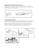


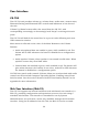
Table Of Contents
- Online Resources
- Contents
- Introduction
- About this Manual
- Getting Started
- User Interface
- Dialer Application
- Basic Operations
- Configuring the CS-700
- Configuring using the Web User Interface
- Configuring using the Service Application
- Configuring using a Provisioning Server, Option 66
- Configuring using a Provisioning Server, Option 150
- Provisioning file
- Provisioning file parameters (All Models)
- Using the Application Programming Interface (API)
- USB API functions
- Telnet / SSH interface
- USB/Telnet/SSH CLI Commands
- usb-conn-status
- speaker-volume
- ringer-volume
- speaker-mute
- mute
- camera-ptz-home
- camera-image-defaults
- camera-backlight
- camera-mute
- camera-pan
- cam-pan-left
- cam-pan-right
- camera-tilt
- cam-tilt-up
- cam-tilt-down
- camera-zoom
- cam-zoom-in
- cam-zoom-out
- cam-apply-defaults
- cam-image-apply-defaults
- status
- status-all
- call-info
- start-time
- dial
- answer
- hangup
- hold
- resume
- swap
- join
- transfer
- vm-count
- do-not-disturb
- dtmf
- registration
- Upgrading the Device Firmware
- Appendix
- Limited Warranty and Limitation of Liability

12
Installing the system
The CS-700 unit is designed to be mounted to the huddle-room wall using the
bracket included with the unit. The recommended mounting location is directly
adjacent to the display unit, typically just below it, with an optimal distance
above the conference room table of 10-18 inches (25 – 45 cm). This provides
an optimum camera perspective for the far-end.
If the CS-700 unit is used in conjunction with a touch-screen or electronic
white board, the preferred installation location is immediately above the screen.
Bracket installation
Install the bracket with 4 appropriate screws on the wall, spacing two pair of
screws as far apart as possible. Ensure that the bracket is tight to the wall or
the spacers to avoid vibration. If installed below the display ensure that the
distance is big enough to fit the CS-700 unit. You can adjust the depth of the
installation by using the appropriate number of spacers (0-2) on each side.
Maximum mounting height is 2m / 6’ 8” from the floor. Always use 4 screws.
0x, 1x, 2x
≥ 3 ¾ in /
95 mm