OWNER’S MANUAL OWNER’S MANUAL M.D.G., EMI Division, Yamaha Corporation © 1999 Yamaha Corporation V484950 This document is printed on chlorine free (ECF) Paper. 910MWCP3.
SPECIAL MESSAGE SECTION PRODUCT SAFETY MARKINGS: Yamaha electronic products may have either labels similar to the graphics shown below or molded/stamped facsimiles of these graphics on the enclosure. The explanation of these graphics appears on this page. Please observe all cautions indicated on this page and those indicated in the safety instruction section. CAUTION RISK OF ELECTRIC SHOCK DO NOT OPEN CAUTION: TO REDUCE THE RISK OF ELECTRIC SHOCK, DO NOT REMOVE COVER (OR BACK).
PRECAUTIONS PLEASE READ CAREFULLY BEFORE PROCEEDING * Please keep these precautions in a safe place for future reference. WARNING Always follow the basic precautions listed below to avoid the possibility of serious injury or even death from electrical shock, short-circuiting, damages, fire or other hazards. These precautions include, but are not limited to, the following: • This instrument contains no user-serviceable parts. Do not attempt to disassemble or modify the internal components in any way.
Introduction Thank you for purchasing the Yamaha CS6x/CS6R Control Synthesizer. Your new CS6x/CS6R synthesizer incorporates the highly-acclaimed AWM2 synthesis engine, allowing the creation of super-realistic sounds. It also supports optional Plug-in Boards that provide other synthesis engines of your choice, enabling the production of cutting edge synthesizer sounds. You can play all these sounds using the synthesizer’s automatic playback facilities such as the built-in Arpeggiator and Sequencer.
Table of Contents Basics Section Basics Section Reference Section The Controls & Connectors ................................6 Voice Mode........................................................74 Before Use ........................................................12 Voice Play ..............................................................74 Power Supply ........................................................12 Voice Edit ..............................................................78 Connections ..
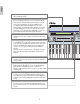
Basics Section Basics Section The Controls & Connectors Front Panel CS6x 1 [VOLUME] Knob (Page 20) Adjusts the master volume. Turn the knob clockwise to raise the output level from the OUTPUT L/R jacks and the PHONES jack. GAIN MIC/LINE 2 LINE 1 L/MONO PHONES A / D INPUT R OUTPUT 1 2 FOOT INDIVIDUAL OUTPUT VOLUM FILTER VOLUME 2 OCTAVE [UP] and [DOWN] keys (Page 28) (CS6x only) Press either of these keys to shift the note range of the keyboard up or down in octaves.
FOOT FOOT T ME CONTROLLER SUSTAIN SWITCH IN BREATH TO HOST OUT HOST SELECT ECT MODE PORTAMENTO REVERB PHRASE CLIP PERFORM REC UTILITY CARD EDIT JOB PITCH SEQ PLAY SUSTAIN VOICE CHORUS ON/ OFF RELEASE THRU MIDI 7 MODE keys (Page 21) Press these to keys to select Voice, Performance, Utility or other Modes. With the CS6R, you can play back (audition) the Voice at note C3 and with a velocity of 127 by pressing the [VOICE] key in Voice Play Mode.
Basics Section 8 LCD (Liquid Crystal Display) This is a backlit 2-line display. 9 [SHIFT] key (Page 23) In Voice or Performance Play Mode, a screen for viewing or setting the Octave parameter and the MIDI Transmit channel (Page 23) is shown when you press the [SHIFT] key. In any of the Edit Modes, when pressing this key while turning the [PAGE] knob, a menu screen is displayed and you can quickly switch between Edit Mode screens (Page 23).
Basics Section ^ [ENTER] key (Pages 24, 25) While selecting a Memory or Bank for Voice or Performance, press this key to determine such a memory location. Also, use this key to execute a Job or a Store operation. & [DEC/NO] key (Page 24) Use this to decrease the value of the parameter at which the cursor is positioned. Also use it to cancel a Job or a Store operation. POWER * [INC/YES] key (Page 24) Use this to increase the value of the parameter at which the cursor is positioned.
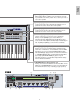
Rear Panel Basics Section 3 CARD slot (Page 171) Insert a Memory Card here to transfer various data to/from the instrument. Read carefully the precautions on use of a Memory Card (Page 171) before using a card. 1 POWER switch (Page 19) Use this to switch the synthesizer on or off. 2 AC INLET terminal (Page 12) Plug the female end of the supplied AC power cord in here before plugging it into an AC wall outlet.
7 BREATH jack (Pages 18, 48) Connect an optional breath controller BC3 here. You can use the Breath Controller to change the output level or tone of the sounds according to the strength of your breath. 8 FOOT SWITCH jack (Pages 18, 48) Connect an optional Foot switch (FC4 or FC5) here. Using the foot switch, you can control of a range of on or off a specific function by foot, as assigned on the instrument.
Basics Section Before Use This section explains how to connect to an AC power source, audio and MIDI devices, and a computer system. Only switch the synthesizer on after you have made all the necessary connections. It is recommended that you read this section before using the synthesizer. Power Supply CS6x/CS6R rear panel AC INLET terminal Power cord (included) 1Make sure that the instrument’s POWER switch is at the OFF position.
Basics Section Connections Connecting to External Audio Equipment Since the synthesizer has no built-in speakers, you need to monitor its sound output via external audio equipment. Alternatively, you could use a pair of headphones. There are several methods of connecting to external audio equipment, as described in the following illustrations. The CS6R also needs an external MIDI controller such as a keyboard, though this is not necessary when using the internal sequencer.
Speaker Speaker Amplifier Basics Section Amplifier L L R Mixer OUTPUT L R Mixer R OUTPUT L R Headphones 1 PHONES 2 3 4 5 OUTPUT L / MONO 6 7 8 9 10 11 12 13 14 15 16 INDIVIDUAL OUTPUT1 R L R 1 INDIVIDUAL OUTPUT2 2 3 4 OUTPUT L / MONO 5 6 7 8 9 10 11 12 13 14 15 16 INDIVIDUAL OUTPUT1 R L R INDIVIDUAL OUTPUT2 C PHONES CS6R CS6x Headphones Connecting a pair of headphones does not affect audio output from the OUTPUT (L/MONO and R) jacks.
You can connect an external MIDI device using a MIDI cable (available separately) and control it from this synthesizer. You can also use an external MIDI keyboard or sequencer to control the synthesizer’s internal sounds. This section introduces several different applications of MIDI. The HOST SELECT switch on the rear panel should be set to “MIDI.” Otherwise, MIDI information will not be transmitted from the synthesizer’s MIDI OUT connector.
Controlling Another MIDI Device via MIDI THRU Basics Section External MIDI sequencer External MIDI synthesizer MIDI OUT MIDI IN MIDI IN MIDI THRU HOST SELECT PC-2 PC-1 MIDI Mac C MIDI IN MIDI OUT External MIDI synthesizer CS6x/CS6R With the above MIDI connections, you can send MIDI data from the MIDI OUT connector while MIDI data from the external sequencer can be sent to an external MIDI synthesizer via the MIDI THRU jack.
Basics Section 2: MIDI Interface to MIDI IN and OUT Using the computer’s MIDI interface HOST SELECT PC-2 PC-1 MIDI Mac Serial cable MIDI IN MIDI OUT Personal System/V PS/V C MIDI OUT MIDI IN CS6x/CS6R Personal System/V IBM Computer with MIDI interface Using an external MIDI interface HOST SELECT MIDI Interface PC-2 PC-1 MIDI Mac MIDI OUT MIDI IN MIDI IN MIDI OUT C Computer CS6x/CS6R You will need to an appropriate MIDI application (sequencer, editor, etc.) for your computer platform.
Connecting Various Controllers Basics Section The CS6x has several controller jacks on the rear panel, including FOOT SWITCH, SUSTAIN, FOOT CONTROLLER, FOOT VOLUME and BREATH. You can connect optional controllers like a Foot Switch (the FC4 or FC5), Foot Controller (the FC7) and Breath Controller (BC3, etc.) to control tone, volume, pitch and other parameters.
Basics Section Powering Up Power-on Procedure When you have made all the necessary connections between your synthesizer and any other devices, make sure that all volume settings are turned down all the way to zero. Then turn on the every device in your setup in the order of MIDI masters (senders), MIDI slaves (receivers), then audio equipment (mixers, amplifiers, speakers, etc.). This ensures the smooth flow of signals from the first device to the last (first MIDI, then audio).
Basics Section If you have a Memory Card inserted in the instrument’s CARD slot or an optional Plug-in Board installed, you may see other screens before the Voice or Performance Play Mode screen is displayed. If a previously used Memory Card is inserted in the CARD slot, you will see a screen while files in EXT Memory are being loaded. If a new Memory Card (one never used on the instrument) is inserted in the CARD slot, you will see a screen while a basic file is being created in EXT Memory.
Basics Section Basic Operations This section gives some basic explanations about operating the synthesizer. Selecting a Mode There are several operation Modes — Voice Play Mode, Performance Play Mode, Phrase Clip Mode, etc. — each of which enables you to work efficiently with the synthesizer’s various functions. An overview of each Mode is given on Page 35. There are separate Play Modes for Voices, Performances and Phrase Clips.
Basics Section 4 Phrase Clip Edit Mode (Page 146) Press the [EDIT] key while in Phrase Clip Play Mode. To exit to another Mode, simply press the respective key for that Mode or press the [EXIT] key to return to Phrase Clip Play Mode. GEN Name) Ctgry Common a-Z 5 Phrase Clip Job Mode (Page 154) Press the [JOB] key while in Phrase Clip Play Mode. To exit to another Mode, simply press the respective key for that Mode or press the [EXIT] key to return to Phrase Clip Play Mode.
Some Modes have more screens. In this case, you can use the [PAGE] knob while holding down the You can switch between screens using the [PAGE] [SHIFT] key to switch to a specific screen. For example, if you use the [PAGE] knob while knob and pressing [SHIFT], PROGRAM/PART, holding down the [SHIFT] key in Voice Edit [EXIT] and [ENTER] keys. Mode, the following screen is shown.
Basics Section [ENTER] Key Moving the Cursor Normally, the [ENTER] key is used to apply parameter settings. In some cases, however, the following screen appears prompting you to press the [ENTER] key. By using a knob ([A], [B], [C], [1] or [2]) while holding down the [SHIFT] key, you can move the cursor (≥) to the respective parameter on the screen without affecting its value.
[DATA] Knob OSCíOut) EL1234 SHIFT PAGE A Level ≥ 96 B Delay 0 C 1 There are many ways to set parameters. Some parameters require you to directly enter numerical settings or alphabetic characters. With others, you can choose from a number of available settings. Furthermore, some types of parameters are “absolute” whereas others are “relative.” InsEF ins2 2 For example, the absolute parameter in the following illustration can be set to either “mono” or “poly.
Basics Section Demo Playback Several demo songs are supplied with this synthesizer. You can play them back as follows. Make sure synthesizer is ready for playback. Details are given in the section “Before Use” on Page 12. At the “SEQ Demo” screen, any data in the instrument’s internal memory (System, Internal Voices, Phrase Clip or the like) will be overwritten by the data for the demo song. Important data should be saved to Memory Card (Page 171) beforehand.
Basics Section Voices and Performances Playing a Voice Based on an AWM2 synthesis engine, this synthesizer offers various kinds of preset Voices (256 Normal Voices and 8 Drum Voices). You can also create your original Voices and store them into the instrument’s internal memory (INT) or an external Memory Card (EXT). The internal and external memory can each contain up to 128 Normal Voices and 2 Drum Voices. You can freely select and play Voices from both groups of memories, as explained in the following.
The Drum Voices are held in separate areas of each Memory, and are accessed as follows. Basics Section • To access the Preset Drum Memories (PRE:DR1 ~ DR8): Press the MEMORY [PRE2] key while holding down the MEMORY [PRE1] key. Now you can play a selected Voice when you play the keyboard on the CS6x or the external keyboard connected to the CS6R. Try auditioning other Voices. Details about selecting Voices using the [DATA] knob or the [DEC/NO] and [INC/YES] keys are given on Page 76.
In Performance Play Mode, you can select and play any of 128 internal and 64 external (Memory Card) Performances. A Performance is a set of Voices used with the built-in (or an external) sequencer. Performances also let you set the synthesizer up for multitimbral operation. Each Performance can contain up to 16 Parts assigned to different Voices, plus extra Parts for Phrase Clip, A/D INPUT and Plug-in Boards.
Basics Section 3 Select a Performance Number using the [DATA] knob or the [INC/YES] and [DEC/NO] keys Turn the [DATA] knob clockwise or press the [INC/YES] key to increment the Performance Number. Turn it anti-clockwise or press the [DEC/NO] key to decrement the Performance Number.
In this section, an overview of the many features of the CS6x/CS6R is given. The CS6x/CS6R hardware is made up of a number of sections, as shown in the following diagram. Controller Section Keyboard (CS6x) Controllers Sequencer Section Tone Generator Section Song File Playback Arpeggiator AWM2 Plug-in Board Phrase Clip Effects Section Controller Section This section consists of the keyboard, Pitch Bend and Modulation Wheels, Ribbon Controller, Sound Control Knobs, and so on.
Tone Generator Section Basics Section This section plays back sounds according to information received from the keyboard and controllers. The following example illustrates the path taken by the signal from an Element in Voice Mode. Tone Generator Section OSC (Oscillator) Outputs the waveform of each Element. Each Voice consists of up to four Elements. PITCH FILTER Controls the pitch of each Element output from OSC. Changes the tonal quality of each Element output from PITCH.
• Virtual Acoustic Plug-in Board (PLG150-VL) With Virtual Acoustic (VA) synthesis, the sounds of real instruments are modeled (simulated) in real time, giving a degree of realism that cannot be achieved using conventional PCM-based synthesis techniques. When playing these sounds using an optional Breath Controller (BC3) or MIDI Wind Controller (WX5), you can even capture some of the physical feel of woodwind instruments.
Basics Section Effects Section The effects can be used to change the sound of a Voice or Performance. There are two Insertion Effect Units plus a Reverb Unit (with 12 types of reverb) and a Chorus Unit (with 23 types of chorus). Each of the Insertion Effect units offers a variety of effects, and the units themselves can be connected in parallel or in series.
About the Modes Voice Mode Voice Play Mode Voice Edit Mode Voice Job Mode Performance Mode Performance Play Mode Performance Edit Mode Performance Job Mode MODE Phrase Clip Mode Phrase Clip Play Mode Phrase Clip Record Mode Phrase Clip Edit Mode Phrase Clip Job Mode PHRASE CLIP REC VOICE PERFORM UTILITY CARD EDIT JOB PITCH Card Mode SEQ PLAY Sequence Play Mode COMPARE PLAY/ STOP STORE Utility Mode Utility Job Mode TEMPO Voice Mode (Page 74) Performance Mode (Page 117) Voice Play Mode N
Basics Section Voices A Voice is a sound created from the many parameters set in the synthesizer. In Voice Play Mode, you can select and play any of these Voices. In Performance Play Mode, several different Voices (known as Parts in this Mode) can be layered and played simultaneously via keyboard or a sequencer. Four groups of Voices are available (Preset 1, Preset 2, Internal and External). Up to two further groups of Voices are available if optional Plug-in Boards have been installed.
Each Voice consists of up of up to four Elements. Each Element itself uses a high-quality waveform. Voice Element 1~4 Element Wave form AWM2: 479 Preset waveforms Internally, there are two Voice Types: Normal Voices and Drum Voices. Normal Voices are mainly musical instrument-type sounds that can be played over the range of the keyboard. Drum Voices are mainly percussion/drum sounds that are assigned to individual notes on the keyboard. A collection of Drum Voice assignments is known as a Drum Kit.
Basics Section Waves Waves are waveforms used as Elements that make up a Voice. 479 high quality preset Waves are available. As shown in the following illustration, when creating a Voice, you can select the Wave to be used as an Element and then set its level, pitch, tone and other parameters.
A Performance consists of up to 20 Parts, each of which can a Normal Voice, Drum Voice, Phrase Clip, A/D Input Part or Plug-in 1/2 Part. By switching on the Layer Switch parameter for different Parts (up to four), you can play back rich layered sounds in Performance Play Mode. You can also create splits so that different Parts are assigned to different areas of the keyboard. If you assign a different MIDI channel number to each Part, each track of a sequencer can play back a different Part.
Basics Section Easy Real-time Editing Sound Control Knobs (CS6x only) The Sound Control knobs allow you for on-the-fly alteration of the tonal characteristics and effects applied to the Voice or Part of a Performance that is currently selected. The functions of each of the knobs are explained here. The altered Voices or Performances can be stored anytime as Scene 1 or Scene 2 (Page 45). When saving each Voice or Performance (Pages 116, 141), its Scene information is also included.
Many features of this synthesizer make it ideal for live performances. These features are explained here. 2 1 Using the Scene (CS6x) Controls (Page 45) Using the Arpeggiator (Page 42) Using the Sound Control knobs, you can edit sounds with ease.
Basics Section 1 Arpeggiator Only notes within the Note Limit range will be arpeggiated. Therefore, if the notes you play are not arpeggiated, they may be outside this range. Details about the Note Limit settings are given later. The arpeggiator is particularly suited to dance/techno music genres. You can assign any The Pitch Bend and Modulation Wheels can be used of 128 Arpeggio Types to each Voice, Performance while the arpeggiator is running. or Clip Kit, and adjust the tempo.
1Press the [EDIT] key in Voice Play Mode. You will enter Voice Edit Mode at the screen where you previously exited. You can play multiple patterns simultaneously by pressing more than one note on the keyboard. MODE VOICE PERFORM ARPíType) Type Tempo Common≥BigBeat2:Dr 92 UTILITY Hold off CARD SHIFT EDIT Switch on PAGE A B C 1 2 DATA JOB PART/ELEMENT COMPARE STORE Now try assigning different Arpeggio Type and Drum Voice settings. There are many different drum patterns available.
Outside the Note Limit range, you can play the keyboard normally without the notes being arpeggiated. Therefore, you can use your left hand to play block chords used by the Arpeggiator and your right hand to play melody lines in the upper part of the keyboard. Setting the Tempo Basics Section You can use Knob [C] to adjust the tempo between 25 and 300 BPM. This parameter setting is used by the Arpeggiator. Use Knob [C] to jump to the Tempo parameter.
2 Scene Controls (CS6x) 2Use the Sound Control knobs and Assignable Knobs [1]/[2] to get the sound that you will store as a Scene. As an example, the illustration below shows two different groups of knob settings (A and B) assigned, respectively, to the SCENE [1] key and the SCENE [2] key. In effect, what this means is that two types of sound can be memorized and recalled for each Voice/Performance.
Basics Section Using the SCENE [CONTROL] Knob Controlling Scenes by Foot Controller (CS6x) By connecting an optional Foot Controller (such as the FC7) to the FOOT CONTROLLER jack on the rear panel of the synthesizer, you can switch between Scenes by foot without having to use your hands. You can set this up as follows. The SCENE [CONTROL] knob lets you create a smooth transition from one Scene to the other, or even a mix between the settings for both Scenes.
CTRL Scene) Sys SHIFT PAGE A Scene Control 04[FootCtrl] B C 1 2 DATA 3 Using Controllers The CS6x is equipped with Pitch Bend and Modulation Wheels, plus a Ribbon Controller. Either of the CS6x and CS6R is equipped with front panel Knobs [A], [B], [C], [1] and [2], with which you can control many different parameters. PART/ELEMENT Pitch Bend Wheel 4 Use the [PAGE] knob to switch to the CTL Assign2 (Voice Control Assign 2) screen.
Basics Section Ribbon Controller (CS6x) Foot Controller (CS6x) The Ribbon Controller is a touch-sensitive controller that lets you control, say, Filter Cutoff in real time by running a finger lightly across its surface to the left or right. Normally, its assigned parameter will increase in value as you run you finger to the right, though you can set it to do the opposite. The Ribbon Controller can be assigned many different parameters (Page 84).
Aftertouch Aftertouch lets you, for example, add vibrato to a sound by applying further pressure to a note on the keyboard while it is being held down. (With the CS6R, an aftertouch-sensitive controller keyboard must be connected.) This allows real-time expression and control. Aftertouch can be used to control a wide variety of parameters (Page 84).
Basics Section Control Sets and External MIDI Control Assigning Parameters to Knobs [A], [B] and [C] In a Control Set, the controllers are assigned to the internal parameters of the synthesizer. However, some controllers were originally designed for a particular purpose, and send pre-defined MIDI Control Change messages when used, regardless of their Control Set allocations within the synthesizer.
The following procedure explains how you can assign a desired parameter to Knob [1] or [2]. You can assign controllers to each Voice (or Part in a Performance) or Clip Kit. Control Settings can be assigned as a Control Set, and a each Controller can be used to control multiple parameters (although this varies according to the type of Voice or Clip kit). Here we introduce an example of how to set up Control Set 1 for Internal Voice 001 (A01) by assigning PCH-Crs (Pitch: Coarse) to Knob [1].
Basics Section 3 Use Knob [C] to select “01:ModWheel” (Modulation Wheel). Controlling Parameters by Foot Controller (CS6x) By connecting an optional Foot Controller (such as the FC7) to the FOOT CONTROLLER jack on the rear panel of the synthesizer, you can control various parameters by foot without having to use your hands. In the following example, we introduce how to set up Foot Controller to work as Modulation Wheel.
Real-world sounds can be recorded or loaded into the synthesizer and played back as musical instruments sounds. The waveform data held in the synthesizer are knows as Phrase Clips. These Phrase Clips are created and played back in Phrase Clip Mode (Page 142). A basic overview of Phrase Clips is given here. MODE VOICE PERFORM UTILITY CARD EDIT JOB Phrase Clips Overview COMPARE STORE 2 Use the [PAGE] knob to switch to the CTRL Other (System Control Other) screen.
Sampling Rate and Bit Resolution Playing Back Phrase Clips Basics Section You can play back your Phrase Clips in three different ways, as follows. As an example, the illustration shows a sine wave. First, there is “loop” playback. A section of the When recording (sampling) the sine wave, the Phrase Clip is continuously looped during A/D converter basically takes snapshots of the playback. This is often used for creating drum wave’s levels at fixed intervals in time. pattern loops from breakbeats.
You can assign Phrase Clips to notes on the keyboard (C0 to C6) and play them live or using a 3Hold down the PHRASE CLIP [REC] key and sequencer. You can also edit various parameters the following screen will be displayed. Here, for each Phrase Clip. The assignment of Phrase you can assign a key to the Phrase Clip you are Clips across the keyboard is known as a Clip Kit, about to record. While still holding down the and you can create up to four of these. key simply press the respective key on the keyboard.
7Press the [ENTER] key and the Recording Standby state is entered. You will see the “Waiting for trigger...” message. Basics Section EF BYPASS EXIT MASTER KEYBOARD ENTER !In Phrase Clip Edit Mode, use the [PAGE] knob to switch to the OSC Asgn screen. Normally you would assign the Phrase Clip to a note on the keyboard (Clip Key) here.
^Next, select Variation 2 but set the Play parameter to “loop” this time. When you press note D1 at this point, the Phrase Clip is simply played back as a loop between the Start and To return to the previous screen, press the [EXIT] End points of the recording. If you only want key. one part of the Phrase Clip to be played back as EF MASTER BYPASS KEYBOARD a loop, you need to set the Start/Loop/End points. As an example, we will set a loop exactly one bar in length.
Basics Section [Clip 001] is now reversed as Variation 1 and looped for one bar as Variation 2, and both Variations can be played by pressing notes C1 and D1. In the same way, you can change the points for Variations 3 to 8 and set up different loops to that of Variation 1/2. £Use Knob [1] to set the Type parameter, which specifies the type of loop change (i.e., which part of the loop will be modified). Combined with the Vari parameter, it is possible to create a variety of loop patterns using Loop Remix.
Basics Section 5 Other Useful Features Portamento Portamento is used to create a smooth transition in pitch from the first note played on the keyboard to the next, and can be used in Voice or Performance Mode. You can switch portamento on/off using the PORTAMENTO [ON/OFF] key on the front panel. When switched on, the PORTAMENTO [ON/OFF] key LED will be lit. You can use the [PORTAMENTO] knob to vary the pitch transition time (Portamento Time). Turn the knob clockwise to lengthen the time.
Voice Edit Basics Section There are 256 Normal Voice presets and 8 Drum 1 Selecting a Voice to Edit Voice presets. You can edit these to create new Enter Voice Play Mode by pressing the [VOICE] Voices, or build completely new Voices from key. scratch. You can then store up to 128 of these new/edited Normal Voices and up to 2 new/edited Drum Voices to internal user memory or external Memory Card. MODE The following procedure gives a basic idea about how to go about creating/editing Voices.
After selecting a Common Edit screen or a edit screen for an Element (1 to 4), use the [PAGE] knob to switch to other screens. Element2 COMMON AMP Scale)Ofst1 EL12_34 + 0 Element3 SHIFT PAGE A B Ofst2 + 0 C Pfst3 - 21 1 Ofst4 - 35 2 DATA Element4 PART/ELEMENT There are many parameters available within a screen. To make editing easier, the knobs below the LCD are assigned to each of the parameters in the screen.
Basics Section • QED (Common Quick Edit) These parameters mostly control the volume and tone of the Voice and you can easily change the overall sound. Many of these parameters can be set directly using the Sound Control knobs on the front panel of the CS6x. QEDíLevel) C 1234 Vol 127 Pan RevSend ChoSend C 127 127 4 OSC (Oscillator) Screens In these screens, you can mainly set the parameters controlling the waveforms on which the Voice is based.
Note Limit C-2 - G 8 Vel Limit 1 - 127 6 FLT (Filter) and FEG (Filter EG) Screens You can use the filter to change the tonal characteristics of each Element, by adjusting overtones (harmonic tones) included in the waveform from the Element. There are several types of filters, but its basic idea is similar.
Basics Section 7 AMP (Amplitude) and AEG (Amplitude EG) Screens 8 LFO (Low Frequency Oscillator) Screens Set the volume of each Element after the OSC (Oscillator), PITCH and FILT (Filter) parameters have been applied, and also the final overall volume of the signal sent to the outputs. The signal of each Element is sent at the specified volume to the next Effect Unit. Also, by setting the AEG (Amplitude Envelope Generator), you can control how the volume changes over time.
Effects in Voice Mode In the final stages of programming, you can set the effects parameters to further change the sound’s character. To generalize, System Effects apply to the overall sound, whether it is a Voice, a Performance, a Song, etc. Insertion Effects, on the other hand, can be applied individually to each Voice. This synthesizer has two System Effect Units (Reverb and Chorus) plus two Insertion Effect Units.
System Effects Mixer Basics Section Reverb Chorus Insertion Effect 1/2 1 2 3 4 5 6 16 Part 1~16 Effect Bypass You can temporarily switch effects off or on by pressing the [EF BYPASS] key. To use this function, you will need to specify the effect to be bypassed in the MSTR EF Bypass screen of Utility Mode (Page 164). You can also specify more than one effect.
As previously explained, your Synthesizer provides several convenient features that you can make use of in a live show or the like. Here we introduce some examples to combine those features to meet your specific purposes. Basics Section Using as a Master Keyboard (Performance Mode) 2Select “Common” using the Knob [A], then open the GEN M. Kbd (General Master Keyboard) screen using the [PAGE] knob. GENíM.
9Turn the [PAGE] knob and open the ARP Type (Arpeggio Type) screen. Set “on” for “Switch.” ARPíType) Type Tempo Part01 UpOct1:Sq 120 Switch on Hold off Basics Section ZONE4 In steps 6 to 9, you now complete settings for the lower range for Arpeggiator performance. It will play in a Voice assigned to Part 1 based on MIDI Receive channel 1. ZONE1 Refer to Page 82 for detailed settings of Arpeggiator. You can copy (reuse) the arpeggio settings that belong to the Voice assigned to Part 1 (Page 141).
PartCL 001(A01)[Dr:Clip Kit] To do this, set “Ch01” to “Ch04” respectively to the “TrnsCh” parameters in the MKB Transmit A necessary Phrase Clip Kit should be prepared screens for Zones 1 to 4. For the “TG” and in Phrase Clip Mode before you use in this setting “MIDI” parameters, set both “on” for Zones 1 in Performance Mode. to 3. For Zone 4, set “off” to “TG” and “on” to #Use the [PAGE] knob and open the Layer Mode “MIDI.” You can switch between multiple (LYR Mode) screen.
Basics Section You don’t need to make further settings for 2Select “Common” using the Knob [A], then Zone 4 since it is not intended for an internal open the GEN M. Kbd (General Master Part and has already been set to output Keyboard) screen using the [PAGE] knob. performance information via the MIDI OUT connector in steps 5 to ). The key range of GENíM.
8As in the same manner in steps 5 to 7, set up for the Upper Part. Select “PartP1” for the Lower Part, go to the MIX Vce (Mix Voice) screen using the [PAGE] knob, and select another Voice (Plug-in Voice) for the Lower Part. Also, go to the LYR Mode (Layer Mode) screen to set the Layer (Layer Switch) to “off” and the RcvCh (MIDI Receiving Channel) to “2.” Note Limit setups are provided for setting Master Keyboard Mode, Part , and Voice. They are associated to one another as follows.
Basics Section Using as a Multitimbral Tone Generator (Performance Mode) Performance Mode lets you use your synthesizer as a 4Next, use the [PAGE] knob to switch to the multitimbral tone generator for use with computerMix Level screen, then set the volume for the based music software or external sequencers. If each piano Part as well as, if necessary, its pan track in a song file uses a different MIDI channel, position, chorus and reverb Send levels.
Part 1 Solo-type Voice Layer=on Part 2 Piano-type Voice Receive Ch. 2 Track 2 Bass Transmit Ch. 3 Part 3 Bass-type Voice Receive Ch. 3 Track 3 Drums Transmit Ch. 10 Part 10 Song File Track 1 Piano Transmit Ch. 2 While playing back the song file with the piano, bass and drum Parts assigned earlier, you can set up the Performance so that you can also play another Part live. Playback using keyboard Performance Part 1 Song File Track 1 Piano Transmit Ch.
Reference Section Voice Mode Voice Mode Voice Play Memory/Voice Program Number PRE1 refers to Preset 1, PRE2 to Preset 2, PRE to Preset Drums, INT to Internal, EXT to External, PLG1 to Plugin Board 1 and PLG2 to Plug-in Board 2. All voice Program Numbers within each memory fall in the range 001 to 128. Drum Voices are DR1 to DR8.
Voice Program Selection 3.Voice Category/Name • Using the BANK/PROGRAM keys (CS6x) • Using the [DEC/NO] and [INC/YES] keys • Using the [DATA] knob • Using the Category Search The two characters to the left of the Voice Name denote the category of instrument or sound to which the voice belongs. Details about Category names are given on Page 80. Voice Name Using the BANK/PROGRAM Keys (CS6x) This consists of up to 10 characters. 1Press a MEMORY key to select a Voice Memory.
Selecting Drum Voices The procedure for selecting a Drum Voice is different to that for selecting a Normal Voice. 3Press a PROGRAM key ([1] to [16]) to select a Program Number. Voices can be selected by setting the Memory, Bank and Program Number as explained in the three steps given above. The LCD also displays the selected voice.
Using the Voice Category Search • Press the MEMORY [EXT] key while holding down the MEMORY [INT] key (or vice versa) to select the Internal/External (INT/EXT) Memory of the User Drum Voice. Then press PROGRAM keys [1] to [4] (CS6x only) to select, respectively, User Drum Voice INT:DR1 (Internal Drum 1), INT:DR2 (Internal Drum 2), EXT:DR1 (External Drum 1) and EXT:DR2 (External Drum 2). With the Voice Category Search, you can quickly find Voices within a specified Voice Category.
Voice Edit There are three kinds of Voices: Normal Voices, Drum Voices and Plug-in Voices (if a Plug-in board has been installed). The following is an explanation of the parameters used to edit each kind of Voice. Voice Mode [DATA] knob (or [INC/YES] or [DEC/NO] key) You can scroll through Voices in the specified Category across the Memories. Turning the [DATA] knob clockwise (or press the [INC/YES] key) jumps to the next Voice number in the same Category, in ascending order.
Voice Store Element1 Element2 COMMON Element3 When creating a new Voice from scratch, it can be useful, prior to editing, to clear the settings for the current Voice using the Initialize Voice function in Voice Job Mode (Page 115). Element4 The í Indicator Normal Voice If you alter any parameters in Voice Edit Mode, the í indicator will be displayed in the top left of the screen. This gives a quick indication that the current voice has been modified but not yet stored.
Voice Mode FLT Sens (Filter Sensitivity) FEG VelSens (FEG Velocity Sensitivity) FEG Time FEG Level FEG Release FLT KeyFlw (Filter Key Follow) FLT Scale (Filter Scale Break Point) FLT Scale (Filter Scale Offset) Element Amplitude AEG VelSens (AEG Velocity Sensitivity) AEG Time AEG Level AEG Release AEG KeyFlw (AEG Key Follow) AEG Scale (AEG Scale Break Point) AEG Scale (AEG Scale Offset) Element LFO (Low Frequency Oscillator) LFO Wave LFO Depth Element EQ (Equalizer) EQ Type EQ Param (EQ Parameter) 95 95 9
Common Quick Edit There are various parameters for Micro Tuning and for controlling how the generated sound is output. Various parameters control the sonic properties of the Voice, and many can also be edited using the Sound Control knobs on the front panel of the CS6x. There are four screens.
■ Sustain Set the level of the Voice maintained while the note on the keyboard is being held down. You can also adjust this parameter using the [SUSTAIN] knob on the front panel of the CS6x. QED Filter (Quick Edit Filter) These parameters control filters which affect the tonal quality of the Voice. If you are using LPF (Low Pass Filter) and HPF (High Pass Filter) combined together, the parameters in the QED Filter page only affects LPF.
■ Vel Mode (Velocity Mode) Set the playback velocity of the Arpeggio. There are 2 modes. ■ Switch Switch the Arpeggiator on or off. You can also set this using the [ARPEGGIO ON/OFF] key on the front panel of the CS6x. ❏ Settings: ❏ Settings: off, on ■ Hold Switch the Arpeggiator Hold on or off. You can also set this using the [ARPEGGIO HOLD] key on the front panel of the CS6x. thru: Velocities of the notes you play are used in the Arpeggio sequence.
Common Controller CTL Bend (Pitch Bend) There are eight Control Settings. You can set the Controller parameters for Portamento, the Pitch Bend Wheel, and for each Element in a Voice. You can set the amount by which the Pitch Bend Wheel changes the pitch of the Voice.
■ Src (Source) Set the Controller used to control the function chosen in Dest. The following nine controllers are available. There are various settings for the LFO. The LFO is used to generate low frequency signals and can be used to create vibrato, wah, tremolo and other effects when applied to pitch/filter/amplitude/etc. parameters. For example, variations can be simultaneously applied to both pitch and filter parameters, and to parameters specific to individual Elements.
■ KeyReset (Key on Reset) Set whether the LFO is reset each time a note is pressed. The following three settings are available. trpzd ❏ Settings: off, each-on, 1st-on Voice Mode off The LFO is self-running (no synchronization) and starts a waveform at any phase when you play on the keyboard. S/H 1 Time Key on S/H 2 each-on The LFO resets with each note you play and starts a waveform at the phase specified by the Phase parameter (see below). Time ■ Speed Set the speed of the LFO Wave modulation.
■ Hold Set the length of time during which the LFO is held at its maximum level. A higher value means a longer Hold time. LFO Fade FadeIn 127 Hold FadeOut 127 127 ❏ Settings: 0 ~ 127 Voice Mode LFOíFade) Delay C 1234 127 Hold ■ Delay Set the delay time before the LFO comes into effect. A higher value means a longer delay time. Max ❏ Settings: 0 ~ 127 Time Short delay ■ FadeOut (Fade-Out) Set the time taken for the LFO effect to be faded out (after the Hold time has elapsed).
■ Dest (Destination) Set the parameters which will be controlled (modulated) by the LFO Wave. EFFíEF2) Ctgry Type Dry/Wet [ENTER] C 123DLY:DelayLCR D
EFF Rev (Reverb) Element OSC (Oscillator) You can select the Reverb Effect Type, then press the [ENTER] key to set its parameters. You can set the parameters for the Elements (Waves) which make up the Voice. Each Voice can consist of up to four Elements, and the following four screens are available for each. Return [ENTER] 127 to Edit OSC Wave (Oscillator Wave) OSC Out (Oscillator Out) OSC Pan (Oscillator Pan) OSC Limit (Oscillator Limit) ■ Type (Reverb Effect Type) Set the Reverb Effect Type.
OSC Limit (Oscillator Limit) Long Delay You can set parameters controlling the note range of each Element and the velocity. OSCíLimit) EL1234 Note Limit C-2 - G 8 Vel Limit 1 - 127 Key on Voice Mode ■ Note Limit Set the lowest and highest notes of the keyboard range for each Element. Each Element will only sound for notes played within its specified range. ■ InsEF (Insertion Effect) Set the Insertion Effect to which the output signal from each Element is sent.
■ Coarse Adjust the pitch of each Element in semitones. ■ Hold (Hold Time) Set the Hold Time. ❏ Settings: -48 ~ 0 ~ +48 ❏ Settings: 0 ~ 127 ■ Attack (Attack Time) Set the Attack Time. ■ Fine Fine-tune the pitch of each Element. ■ Decay1 (Decay 1 Time) Set the Decay 1 Time. ■ Random Set the amount by which the pitch of each Element is varied at random for each note you press. A setting of zero means the original pitch is not changed. ❏ Settings: 0 ~ 127 ■ Decay2 (Decay 2 Time) Set the Decay 2 Time.
■ Time (Release Time) Set the Release Time. ■ Center (Center Key) Set the basic pitch used by the Pitch parameter. ❏ Settings: 0 ~ 127 ❏ Settings: C-2 ~ G8 You can also set this parameter by pressing the respective note on the keyboard while holding down the [SHIFT] key. ■ Level (Release Level) Set the Release Level.
Element Filter LPF24D (Low Pass Filter 24dB/oct Digital) A 4-pole (-24db/oct) dynamic LPF with a strong Resonance. You can set Filter parameters to change the tonal characteristics of each Element. The following ten screens are available.
• HPF (High Pass Filter) This only passes signals above the Cutoff frequency. You can then use the Reso (Resonance) parameter to add further character to the sound. Two types of HPF are available. BPF6 (Band Pass Filter 6dB/oct) The combination of a -6dB/oct HPF and LPF. Level Cutoff range Range passed Cutoff range -6db/oct Level Voice Mode Frequency BPF12D (Band Pass Filter 12dB/oct Digital) The combination of a -12dB/oct HPF and LPF.
■ EGDepth Set the sensitivity of the Filter to note velocity. A positive setting will produce large filter changes for notes played harder, and a setting of zero will produce no filter changes at all. With a negative setting, the EG envelope will be inverted. ❏ Settings: 0 ~ 255 ■ Reso (Resonance)/Band/Width This parameter’s function varies according to the selected Filter Type. If an LPF or HPF has been selected, this parameter is used to set the Resonance.
Voice Mode FEG Time FEG Release You can set various Time parameters for the Filter Envelope Generator (FEG). Combined with the FEG Level and FEG Release settings, these can be used control the change in sound from the moment a note is pressed on the keyboard to the moment it is released. You can set different values for each Element. You can set Release Time and Release Level parameters for the Filter Envelope Generator (FEG).
■ Cutoff Set the Filter Key Follow ratio (the amount by which the Filter Cutoff varies according to note position) for each Element. A Center Key setting of C3 is used as the basic setting by the Cutoff parameter. A positive setting will lower the Cutoff frequency for lower notes and raise it for higher notes. A negative setting will have the opposite effect. You can set four Filter Scaling Break Points for each Element.
■ Attack (Attack Time) Set the Attack Time. Element Amplitude You can set Amplitude parameters to affect the output level of each Element. The following seven screens are available. ❏ Settings: 0 ~ 127 ■ Decay1 (Decay 1 Time) Set the Decay 1 Time. Voice Mode AEG VelSens (AEG Velocity Sensitivity) AEG Time AEG Level AEG Release AMP KeyFlw (AMP Key Follow) AMP Scale (AMP Scale Break Point) AMP Scale (AMP Scale Offset) ❏ Settings: 0 ~ 127 ■ Decay2 (Decay 2 Time) Set the Decay 2 Time.
■ Level (Release Level) This shows the Release Level. (Fixed at zero.) ■ Center (Center Key) This shows that the basic Level is at note C3. At this note, the output level remains unchanged. For other notes, the output levels vary according to the Level settings. The Center setting cannot be changed. Amplitude Envelope Generator Settings There are four Time settings (controlling the speed of changes in output level) and five Level settings (controlling the output level).
AMP Scale (AMP Scaling Break Point) The Break Point Levels are Offsets used to increase or decrease the current amplitude at the specified notes. Regardless of the size of these Offsets, the minimum and maximum amplitude limits (values of 0 and 127, respectively) cannot be breached. You can set four Amplitude Scaling Break Points for each Element. Amplitude Scaling controls the amplitude according to the positions of the notes on the keyboard.
■ Speed Set the speed of the LFO waveform. A larger setting means a faster speed. ■ AMod (Amplitude Modulation Depth) Set the amount (depth) by which the LFO waveform varies (modulates) the amplitude of the sound. A larger setting means a larger modulation depth. ❏ Settings: 0 ~ 63 ❏ Settings: 0 ~ 127 Element EQ (Equalizer) You can set the following two Equalizer parameters for each Element.
■ LoFreq (Low Frequency) Set the low frequency of the Shelving filter. Frequencies below this point are attenuated or boosted by the Low Gain parameter. ■ Q (Frequency Characteristic) Set the Q (Frequency Characteristic). 32 different Characteristics are available. ❏ Settings: 0 ~ 31 ❏ Settings: 50.1Hz ~ 2.00kHz Voice Mode • Boost6 (Boost 6dB)/Boost12 (Boost 12dB)/ Boost18 (Boost 18dB) These can be used to boost the level of the entire signal by 6dB, 12dB and 18dB, respectively.
Drum Common General 106 106 106 106 106 107 107 101 101 101 For Drum Voices, there is only the one type of Common General parameter shown below. The parameter settings is the same as for Normal Voices. Details are given on Page 80. GEN Name (General Name) Drum Common Quick Edit The following four screens are available for Drum Voice output level and timbre parameters. These can also be edited using the Sound Control knobs on the CS6x front panel.
■ Attack Set the Attack time (the time from the moment the note is pressed to the point at which the maximum sound output level is reached). The [ATTACK] knob on the CS6x front panel can also be used to directly adjust the Attack time. Drum Key OSC (Oscillator) Voice Mode You can change your Drum Voice waveform settings. Each Drum Voice can consist of up to 73 Drum Keys (Page 37), assigned to notes spread across the keyboard (C0 to C6). You can assign waveforms to Drum Keys and set their parameters.
■ Pan Set the Pan position for each sound in a Drum Voice (Drum Kit). This will also be used as the basic Pan position for the Alternate and Random settings. OSC Out (Oscillator Out) Set the Wave or Normal Voice output settings for each Drum Key. Level 127 InsEF RevSend ChoSend thru 64 127 ■ Alter (Alternate) Set the amount by which the sound is panned alternately left and right for each note you press. The Pan setting is used as the basic Pan position.
■ RcvNtOff (Receive Note Off) Select whether MIDI Note Off messages are received by each Drum Key. Drum Key Filter You can apply filter settings to the Drum Voice. A Low Pass Filter and High Pass Filter can be applied per Wave to change its tonal characteristics. ❏ Settings: off, on This parameter depends on the Type of Drum Key Wave chosen in the OSC Wave screen. This parameter is only available if the Type parameter in the OSC Wave screen is set to “wave.
■ AMP AEG (Amplitude Envelope Generator) The Amplitude Envelope Generator controls the change in amplitude from the moment a note in pressed on the keyboard to the moment it is released. By setting the Attack Time, Decay 1 Time and the Decay 1/2 Level, you can determine how fast the sound reaches its peak amplitude and how it fades out. Parameters can be set for each Drum Key. The Amplitude Envelope Generator has three Time parameters and one Level parameter.
Plug-in Voices The Voices held on Plug-in Boards (Single Part) are known as Board Voices. A Plug-in Voice is a Board Voice that has been processed in the synthesizer in Voice Edit Mode. There are six Common Edit screens and four screens for editing the Element of a Plug-in Voice. You can save up to 64 edited Plug-in Voices in Banks A to D of Memory PLG1/2.
Plug-in Common General QED Filter (Quick Edit Filter) The General parameters are shown in the following two screens. The parameters and settings are the same as for Normal Voices. Details are given on Page 82. GEN Name (General Name) GEN Other (General Other) The EG (Envelope Generator) can be used to control the change in Plug-in Voice volume over time.
Plug-in Common Controller CTL MW Control (MW Control Depth) You can set Pitch Bend Wheel, Modulation Wheel and other Controller parameters for the Plug-in Voices in the following nine screens. Here, you can set the depth of control the Modulation Wheel has over the filter.
■ PMod (Pitch Modulation Depth) Set the depth of control the Control Change messages (selected in the Source parameter) have over the pitch modulation. The larger the setting, the greater the depth of control. CTL AT Modulation (AT Modulation Depth) Here, you can set the depth of control that keyboard aftertouch has over the pitch, filter and amplitude modulation of the Plug-in Voice.
■ Delay Set the delay time between the moment you press a note on the keyboard and the moment the LFO comes into effect. As shown in the illustration, a positive setting will lengthen the delay and a negative setting will shorten it. OSC Assign (Oscillator Assign) You can select the Board Voice that make up the Element in a Plug-in Voice. Use Knob [C] to select the Bank and Knob [1] to select the Board Voice.
PCH PEG (Pitch Envelope Generator) EQíParam)LoFreq Elem 2.0k Attack Release---Level +63 +63 -64 HiFreq 16.0k HiGain -12dB + ■ InitLvl (Initial Level) Set the Initial Level. ❏ Settings: -64 ~ 0 ~ +63 0 Frequency ■ Attack Set the Attack Time. Low Freq ❏ Settings: -64 ~ 0 ~ +63 ■ Release Set the Release Time. High Freq ■ LoFreq (Low Frequency) Set the shelving point for the low frequencies.
If a Board Voice in the Custom Bank has been edited in Voice Edit Mode, you can store it as a Plug-in Voice in Memory Bank A to D of PLG1 or PLG2. Up to 64 can be stored in each Bank. Editing Plug-in Board Voices Plug-in Voices are based on Board Voices. However, the Board Voices themselves can be edited via computer, using the included editor software. Different editors are available for different Plug-in Boards. Voice Mode However, only the Voice Edit parameters can be stored.
Voice Job Mode You can reset (initialize) all parameters of a Voice to their default settings. You can also selectively initialize certain parameters, such as Common settings, settings for each Element/Drum Key, and so on. Note that this does not return the Voice to its original state prior to editing. Instead, it is useful when building a completely new Voice from scratch. You can perform various operations (Jobs) in Voice Job Mode.
■ 1 Source Voice Memory Select the Voice Memory containing the Voice (source) from which you will copy parameter settings. Voice Store You can store (save) the parameter settings for up to 128 Voices to each of your synthesizer’s Memories (INT: Internal) or to its Memory Card (EXT: External). The procedure is as follows.
Performance Mode Performance Play In Performance Play Mode, multiple Voices (up to four Parts) can be layered to create thick sounds which you can play in real-time or using a sequencer. 3rd screen: 4th screen: 5th screen: 6th screen: 7th screen: In Performance Mode, up to 20 Parts can be combined in a single Performance, including Voices for the 16 Parts plus Phrase Clip, A/D Input and Plug-in 1/2 Parts.
4.
Performance Program Selection Details about Banks are given on Page 29. 3Press a PROGRAM key ([1] to [16]) to select a Program Number. Performances can be selected by setting the Memory, Bank and Program Number as explained in the three steps given above. The display also shows the selected Performance.
3Use Knob [B] or the [DATA] knob or the [DEC/NO] and [INC/YES] keys to adjust the parameter settings for each Part. ■ 3rd Screen: PFM Mlt) Volume (Performance Multi: Volume) Set the output level (volume) of each Part. 4Repeat steps 2 and 3 for each of the other Parts. PFM*Mlt) Volume Part01 127 To avoid losing the settings, make sure you store the Performance before exiting to another Mode or selecting another Performance. Details about how to store Performances are given on Page 141.
Performance Edit the Common Edit screen and screens for editing each Part individually. When editing individual Parts, the screens you see will vary depending on the Part selected. If the synthesizer is in Master Keyboard Mode (Pages 8, 67), you will be able to set parameters for each Zone. In Performance Edit Mode, use Knob [A] to switch between the screens for Common, Part and Zone settings. You can set Performance Edit parameters.
Tone Generator Mode: [MASTER KEYBOARD] key LED off The “Compare” Function Use this to listen to the difference between the Performance with your edited settings and the same Performance prior to editing. MIDI IN MIDI channel Octave Transpose Note Limit etc. 1 Press the [EDIT/COMPARE] key while in Performance Edit Mode. The í indicator at the top left of the screen will change to the î indicator and the [EDIT/COMPARE] key LED will blink.
Common General GEN M.Kbd (General Master Keyboard) You can set the Performance Name, MIDI channel and other general parameters in the Common Edit screens. The following three screens are available for general settings. You can set keyboard splits and layers when using a Performance in Master Keyboard Mode. You can set a Performance Name consisting of up to 10 characters (alphabetic or numeric) and/or symbols. You can also select the Category Name to the left of the Performance Name.
■ Point When the Mode (see earlier) has been set to “split,” this sets the split point. The actual note of the split point will be assigned to the upper section. QED Level (Quick Edit Level) You can set output level and pan parameters for each Layer Part. The settings are also available in the Part Edit screens. You can also select the split point by pressing the note while holding down the [SHIFT] key.
■ Time Set the pitch transition time. Higher values mean longer transition times. You can also set this using the PORTAMENTO knob on the front panel of the CS6x. ■ Attack Set the transition time from the moment a key on the keyboard is pressed to the point at which the output level of the Layer Part reaches its peak. You can also adjust this parameter using the [ATTACK] knob on the front panel of the CS6x.
■ Mode Set the behavior of the Ribbon Controller. If you select “hold,” the parameter controlled by the Ribbon Controller will hold its value even after you release it. If you select “reset,” the value returns to its default setting at the center of the Ribbon Controller strip. CTL Assign1(Controller Assign 1) Use Knobs [C], [1] and [2] to assign Control Numbers to the Breath Controller, Knob [1] and Knob [2], respectively. The selected function is shown on the left of the display.
■ Freq (Frequency) Set the center frequency. Frequencies around this point are attenuated/boosted by the Gain setting. peak (Peaking) + ❏ Settings: 100Hz ~ 10.0kHz 0 Gain ■ Q (Frequency Characteristic) This varies the signal level at the Frequency setting to create various frequency curve characteristics. Frequency - ❏ Settings: 0.1 ~ 12.0 Freq This Equalizer covers high frequencies. You can adjust the signal level at the specified frequency. You can also select different Equalizer types (Shapes).
■ InsEF (Insertion Effect) Assign a Part to an Insertion Effect. Select “off” if you do not wish to assign the Part to an Insertion Effect. Furthermore, if Plug-in Boards have been installed, they will also be selectable as Plug-in Parts 1 and 2. ■ Type (Chorus Effect Type) Set the Chorus Effect Type. ❏ Settings: Details are given in the Effect Types list of the separate Data List. ■ toRev (To Reverb) Set the Send level of the signal sent from the Chorus Effect to the Reverb Effect.
Part (Settings for each Part) Use Knob [B] to select PLG1/2INT (internal memory) and the MSB/LSB (Plug-in Board’s Bank), and use Knob [C] to select the Program Number. You can edit each Part in a Performance. Use Knob [A] to select the Part, then set its parameters. The following six screens are available, though their contents will vary according to the Part selected.
■ Vol (Volume) Set the output level of the Part. • If PartAD (A/D Input Part) has been selected ❏ Settings: 0 ~ 127 An audio source connected to the A/D INPUT jack can be used as a Part. There are 13 different templates for Effect Type and Gain settings. Select the A/D Input Part source and the template. ■ Pan Set the stereo pan position of the Part.
■ Reso (Resonance) Set the amount of Resonance (harmonic emphasis) applied to the signal at the Cutoff frequency. This adds further character to the sound. ■ Release Set the transition time from the point at which the note on the keyboard is released to the point at which the output level of the Part reaches zero. A positive value will lengthen the transition time and a negative value will shorten it. ❏ Settings: -64 ~ 0 ~ +63 This parameter is not available for Phrase Clip or Drum Voice Parts.
Offset (Velocity Offset) TON Other (Tone Other) As illustrated below, the velocity will be increased by the specified amount. You can set Pitch Bend Range and Velocity Sensitivity parameters for each Part. Changes to velocity curve according to VelDepth (with offset set to 64) These screens are not available for the A/D Input Part.
■ Mode Select whether each Part is played back monophonically (single notes only) or polyphonically (multiple simultaneous notes). ■ Vel Limit Set the minimum and maximum values of the velocity range within which each Part will respond. Each Part will only sound for notes played within its specified velocity range. This parameter is only available for Normal Voice Parts 1 to 16 and Plug-in 1/2 Parts.
■ InsEF (Insertion Effect) Shows the on/off status of the Insertion Effects. If “on” is displayed, this means that the Part’s signal is being sent to the Insertion Effect Unit. Parts 1 to 16 Drum Voice Part Phrase Clip Part RCVíSw2) Part01 Insertion Effect switches for each Part are set in the EFF Part screen (Page 127). Each Part can be set to receive Control Change and Program Change messages. The following four screens are available.
Part Controller ■ Dest (Destination) Set the parameter to be controlled by the Controller specified in Src. You can set various Controller parameters for the A/D Input Part and Multi Plug-in Parts 17 to 32. The following two screens for A/D Input Part parameters and six screens for the Multi Plug-in Part parameters are available. ❏ Settings: see the separate Control List. ■ Depth (Depth) Set the amount by which the parameter selected in Dest can be controlled.
■ FMod (Filter Modulation Depth) Set the amount by which the filter Cutoff frequency changes when the Modulation Wheel is used. ■ FMod (Filter Modulation Depth) Set the amount by which the filter Cutoff frequency changes when aftertouch is used. ❏ Settings: 0 ~ 127 ❏ Settings: 0 ~ 127 ■ AMod (Amplitude Modulation Depth) Set the amount by which the amplitude modulation changes when the Modulation Wheel is used.
■ FMod (Filter Modulation Depth) Set the amount by which the filter Cutoff frequency changes when the controller (Source) is used. Effect Parameter Settings These parameters are available when you press the [ENTER] key for certain Effect Types. Use the [PAGE] knob to switch between screens, and use the other knobs and the [INC/YES] and [DEC/NO] keys to set each parameter. When you press the [EXIT] key, you will be returned to the Effect Type selection screen.
Master keyboard MKB TxSw1 (Master Keyboard Transmit Switch 1) MKB Transmit (Master Keyboard Transmit) For each zone, you can enable/disable the transmission of messages for the Pitch Bend Wheel, Modulation Wheel, Knobs [A] to [C] and Knob [1]/[2]. You can set parameters for transmitting keyboard data when in Master Keyboard Mode.
■ PC (MIDI Program Change) Set the Program Number transmitted when changing Bank/Program. MKB TxPreset1 (Master Keyboard Transmit Preset 1) You can set each zone’s initial volume and stereo pan settings when changing Performance Bank/Program. MKBíTxPreset1) Zone01 Volume 127 ❏ Settings: 1 ~ 128 Program Numbers 001 to 128 directly relate to MIDI Program Change Numbers 000 to 127. That is, Program Numbers and Program Change Numbers differ by a value of 1. Remember to take this into consideration.
Performance Job Mode PFM Initialize You can reset (initialize) all parameters of a Performance to their default settings. You can also selectively initialize certain parameters, such as Common settings, settings for each Part, and so on. Note that this is not the same as editing an existing Performance. Instead, it is useful when building a completely new Performance from scratch. You can execute various actions (Jobs) in Performance Job Mode.
2Source Performance Number Select the Performance Number of the source Performance. The Performance Name is shown in the top line of the display. Performance Store You can store the parameter settings for up to 128 Performances to each of your synthesizer’s Memories (INT: Internal) or up to 64 Performances to Memory Card (EXT: External). The procedure is as follows.
Phrase Clip Mode Phrase Clip Play Clip Kit Name In Phrase Clip Play Mode, you can select one of four Clip Kits. A Clip Kit is a collection of Phrase Clips (external sounds recorded via microphone, from audio equipment or from other sources) assigned to notes across the keyboard for playback. A Clip Kit can consist of Drum loops or phrases, and can be assigned to a Part in a Performance (Page 39). The screens displayed in Phrase Clip Play Mode are explained here. 4.
Phrase Clip Record Using the [DEC/NO] and [INC/YES] Keys If you press the [INC/YES] key, the next Clip Kit is selected and displayed. Pressing the [DEC/NO] key selects the previous Clip Kit. DEC/NO INC/YES Previous Number Next Number Using the [DATA] Knob Turn the [DATA] knob clockwise to increment the Clip Kit Number and anti-clockwise to decrement it. C 1 2 Phrase Clips are stored to Memory Card in a proprietary file format. Details about saving files are given on Page 173.
■ Source Select the Source from which you will record. The Level Screen When you are recording from a “mic” or “line” level source in Phrase Clip Record Mode, use the [PAGE] knob to turn to the following screen. You will see the Input Level pointer and the Trigger Level pointer. Here, you can use the Input Level pointer and Trigger Level pointer to check the Trigger Level and the level of the signal at the A/D INPUT connector.
If set to “manual”: Recording will begin when you press the [ENTER] key. PCLP Rec) Source Trigger << Now recording... >> [EXIT] toStop If set to “level”: Press the [ENTER] key to enter Recording Standby state. You will see the “Waiting for trigger” message displayed. When the level of the input signal reaches or passes the Trigger Level, recording begins automatically. PCLP Rec) Source Trigger-level << Waiting for trigger... >> [EXIT] toStop While recording, you will see the “Now recording...
Phrase Clip Edit Phrase Clip Edit Mode Common Clip Common General GEN Name (General Name) Clip Common Quick Edit QED Level (Quick Edit Level) QED EffectCtrl (Quick Edit Effect) QED Filter (Quick Edit Filter) QED EG (Quick Edit Envelope Generator) Clip Common Arpeggio ARP Type (Arpeggio Type) ARP Limit (Arpeggio Note Limit) ARP Mode (Arpeggio Mode) ARP PlayEF (Arpeggio Play Effect) Clip Common Controller CTL Set1 (Control Set 1) CTL Set2 (Control Set 2) CTL Set3 (Control Set 3) CTL Set4 (Control Set 4) CTL
Menu Display You will see the following if you use the [PAGE] knob while holding down the [SHIFT] key. Use the [PAGE] knob to move the cursor to the parameter you wish to edit, then release the [SHIFT] key to jump to the screen you were previously at. Clip Common General GEN Name (General Name) You can set a Clip Kit Name consisting of up to 10 characters. You can also select the Category Name to the left of the Clip Kit Name.
■ ChoSend (Chorus Send) Set the Send level of the signal sent from Insertion Effect 1/2 (or the bypassed signal) to the Chorus effect. You can also adjust this parameter using the [CHORUS] knob on the front panel of the CS6x. QED EG (Quick Edit Envelope Generator) These two parameters control the change in the output level of a Clip Kit over the time that a note is played.
CTL Bend (Pitch Bend) Clip Common Effect You can set a range of pitch change controlled by Pitch Bend Wheel. You can set two types of Insertion Effects, plus two System Effects (Reverb and Chorus). The following five screens are available. The parameters are the same as those used in Voice Edit Mode. Details are given on Page 88.
■ Play (Play Mode) Select the Phrase Clip playback method. There are three modes. Variation Settings You can play back a Phrase Clip in up to eight different ways (Variations). They are related to the Clip Kit as shown in the illustration. ❏ Settings: loop: When you press a note on the keyboard, the Phrase Clip is played completely from its Start Point. Then its looped section is played back repetitively until you release the note.
■ ChoSend (Chorus Send) Set the Send level of the Clip Key signal sent from Insertion Effect 1/2 (or the bypassed signal) to the Chorus effect. Looped Section ❏ Settings: 0 ~ 127 Details about Effects are given on Page 65. OSC Pan (Oscillator Pan) End Point You can set the following Pan parameters for each Clip Key in the Clip Kit. ❏ Settings: Depends on the length of the Phrase Clip ■ End (End Point) Set the End Point of the Phrase Clip’s looped section.
■ KeyOn Select the Key On method. There are two methods: normal and hold. Clip Key Filter You can apply filter settings to Clip Keys. A Low Pass Filter and High Pass Filter can be applied per Phrase Clip to change its tonal characteristics. ❏ Settings: normal: Pressing a Clip Key starts playback of a Clip. Playback will continue until the key is released. FLT Cutoff (Filter Cutoff) hold: Pressing a Clip Key triggers playback of a Clip.
AMP AEG (Amplitude Envelope Generator) Amplitude Envelope Generator Settings The Amplitude Envelope Generator controls the change in amplitude from the moment a note in pressed on the keyboard to the moment it is released. By setting the Attack Time, Decay 1/2 Time and the Decay 1 Level, you can determine how fast the sound reaches its peak amplitude and how it fades out. Parameters can be set for each Clip Key. Decay1---Level 127 127 Decay2 127 ■ Attack (Attack Time) Set the Attack Time.
5When you press the [ENTER] key, you will see a confirmation message. Phrase Clip Job Mode In the Mode, you can execute various operations (jobs) on the Phrase Clips that you have created/edited in Phrase Clip Edit Mode, such as delete, copy and normalize. You will see the 1st screen (PCLP Status) when you enter Phrase Clip Job Mode. There are 14 screens for Phrase Clip Jobs, as follows. PCLP LoopRemix) << Are You Sure The Job will be canceled if you press the [DEC/NO] key.
PCLP Rename PCLP LoopDivide You can change the Phrase Clip Name for each Phrase Clip. A Phrase Clip Name can consist of up to eight characters. To select each Phrase Clip, use Knob [A] to select the Clip Key and use Knob [B] to select the Phrase Clip Number. For each Phrase Clip, you can set the Variation length as a percentage. The Phrase Clip can be divided into a number of equal-sized sections which make up a Variation Set. These sections can then be assigned to consecutive notes on the keyboard.
1At this screen, you can play back the currently selected Phrase Clip as a loop. ■ Length Set the Variation length ratio. You can change the length of all the equal-sized sections by the amount set here. If you select “toEnd,” the End Point of the source Phrase Clip will be used as the End Point of the Variation (after it has been divided). 2Set the Start Points for Variations 1 to 8 by pressing notes C3 to C4 on the keyboard.
4When you press the [ENTER] key, you will see a confirmation message. Press the [INC/YES] key to execute the Loop Remix Job. The Job will be canceled if you press the [DEC/NO] key. ■ Start (Start Point) Set the Start Point from which the Phrase Clip will be played back. By finely adjusting the Start Point, you can avoid playback of the noise before the Start Point. This setting, however, does not eliminate the noise in the original Clip.
■ TargetVari (Target Variation) Set the areas to be removed by PCLP Extract. PCLP FreqConvert (Frequency Convert) You can perform a Frequency Convert operation on each Phrase Clip. This halves its sampling rate and therefore its size. ❏ Settings: all Unused areas of all eight Variations are removed. To select each Phrase Clip, use Knob [A] to select the Clip Key or Knob [B] to select the Phrase Clip Number. After selecting the Phrase Clip, press the [ENTER] key to execute the Frequency Convert operation.
PCLP Copy PCLP AutoKeyMap You can copy the data of each Phrase Clip to another Phrase Clip. Auto Key Map is used to automatically assign Variations of a Phrase Clip to notes on the keyboard, starting at the Clip Key note. To select each Phrase Clip, use Knob [A] to select Clip Key or Knob [B] to select the Phrase Clip Number. After selecting the Phrase Clip, press the [ENTER] key to copy it to an automatically allocated (vacant) Phrase Clip Number.
■ Destination Clip Key Select the Clip Key to which the Source Clip Key will be copied. Clip Kit Store You can store up to four edited Clip Kits to internal memory as follows. ❏ Settings: C0 ~ C6 Existing Clip Kit data will be overwritten with the new data when stored. You should save important data to Memory Card beforehand. PCLP Kit Key Initialize Clip Kit data stored in internal memory will be lost when you switch the synthesizer off.
Sequence Play Mode In this Mode, you can play back the built-in demo songs and Song files stored on Memory Card. Up to 100 Song files can be played back end-to-end by using the Chain Step feature. This Chain Step data can also be saved to Memory Card. The Demo Songs contain preset tempos by default. When you switch to another Demo Song, its preset tempo will be used. You can change the playback tempo. To restore the default tempo, select “***” as the tempo setting.
■ Song File Number Assign a Song file to the Chain Step. Any Song files with the “.MID” extension can be selected. When you select a file Number here, the file name is shown in the top line of the display. For continuous (chained) playback of multiple Chain Steps, you can specify how to play this Chain Step after playback of a previous one by selecting an option from among “skip,” “end” and “stop.” If you select “skip,” the Chain Step is skipped and playback will jump to the next Chain Step.
Utility Mode The parameters in Utility Mode are explained here. Utility Mode can roughly be divided into a screen for settings common to the entire system, a screen for Voice Mode settings and a screen for Plug-in Board settings. MSTR (System Master) You can set the overall parameters, including volume and pitch, which mainly relate to the synthesizer’s tone generator section. The following four screens are available. You will first see the following screen when you enter Utility Mode.
■ Vel (Keyboard Velocity Curve) Set the Velocity Curve determining how the strength of the notes played will affect the sound output. MSTR EF Bypass (Master Effect By-pass) Set the parameters related to the [EF BYPASS] key on the front panel. ❏ Settings: norm, soft, hard, wide, fixed norm (Normal) The velocity is in proportion to the strength.
■ BCCurve (TG Breath Curve) Set the Breath Curve determining how the strength with which you blow into the Breath Controller will affect the sound output. ■ CC# (Control Number) Assign MIDI Control Change Numbers to Assignable Knobs [A] to [C]. ❏ Settings: 000 ~ 095 (see the separate Data List for details) ❏ Settings: thru, soft, hard, wide ■ Dest (Control Destination) Set the function to be controlled by Assignable Knobs [A] to [C].
■ Switch Select the Control Change Number used to control the ARPEGGIO [ON/OFF] key. MIDI (System MIDI) You can set overall MIDI parameters for the system. The following five screens are available. ❏ Settings: 000 ~ 095 (000, 032 = off) MIDI Ch (MIDI Channel) MIDI Arp (MIDI Arpeggio) MIDI RxSW (MIDI Receive Switch) MIDI Other MIDI GM/XG Receive ■ Hold Select the Control Change Number used to control the ARPEGGIO [HOLD] key.
■ PgmChng (Program Change) Set to enable or disable reception of a Program Change message coming in. With this parameter set to “on,” the instrument can receive a Program Change massage coming in, and it can also send a Program Change out to an external MIDI device when you select a Voice or Performance (using a [PROGRAM/PART] key, etc.) on its front panel. MIDI GM/XG Receive (if a Multi-Part Plug-in Board has been installed) Set GM On and XG Reset Receive parameters.
M.EQ Low (Master EQ Low) ■ Gain Set the Gain. This attenuates or boosts frequencies around the Frequency setting. This Equalizer covers low frequencies. You can adjust the signal level at the specified frequency. You can also select different Equalizer types (Shapes). M.EQ Low) Shape Vce peak Gain +12dB Freq 50Hz ❏ Settings: -12dB ~ 0dB ~ +12dB ■ Freq (Frequency) Set the center frequency. Frequencies around this point are attenuated/boosted by the Gain setting. Q 12.
■ RB (Ribbon Controller) Assign a Control Change Number to the Ribbon Controller on the front panel. The Ribbon Controller’s behavior depends on the Mode parameter setting. Details about Controller Assign settings in Performance mode are given on Page 126. CTRL Assign1 (Controller Assign 1) Use Knobs [C], [1] and [2] to assign Control Change Numbers to the Breath Controller, Knob [1] and Knob [2], respectively. The selected Control Change Name is shown on the left of the display.
■ Clock Select whether or not to transmit MIDI Clock messages to the Plug-in Board. Now, the tempo of the Plug-in Board is synchronized with the MIDI clock signal received from the CS6x/CS6R. To synchronize with an external MIDI clock source, enter Utility Mode and set the Sync parameter of the MIDI Other screen to “MIDI.” ❏ Settings: off, on ■ DevNo (Device Number) Set the MIDI Device Number of the Plug-in Board.
Card Mode In Card Mode, you can use Memory Card, a SmartMedia™ card available at a consumer electronics shop, etc., to save or load data from/to the instrument or perform other data exchange operations between memories on the instrument and the Card. Using the included Card Filer software, you can use a computer to manage data on Memory Card. You can also use it to exchange data between the computer and Memory Card.
■ SMF (Standard MIDI Files) Format 0 Standard MIDI Files (SMFs) can be played back in Song Mode. However, they cannot be saved. You will see the 1st screen (Status) when you enter Card Mode. The following seven screens are available, each for a different operation. ❏ Extension: “.
Card Mode Operations Status 1Insert the Memory Card into the CARD slot. You can view the amount of free and used on the Memory Card. There are no settings. 2Press the [CARD] key to enter Card Mode. 3Use the [PAGE] knob to switch to the screen for the operation you wish to perform. SHIFT PAGE A Type all B File A-? Cursor ***[NEWFILE .S2A] C 1 2 DATA ■ Free Shows the amount of free memory on the Memory Card.
4Press the [INC/YES] key to save the file. The message “Completed.” will be displayed after it has been saved, and you will be returned to the previous screen. The save operation will be canceled if you press the [DEC/NO] key during execution. 1Use Knob [B] to select the File Type of the data to be loaded. 2Use Knob [C] to select the File Number. 3When you press the [ENTER] key, the following will be displayed, depending on the selected File Type.
voice [Pf:Init Voice] [Pf:Init Voice] EXT:064(D16) > INT:128(H16) Voice Memory of Voice Memory to file to be loaded (source) which file will be loaded (target) Voice Number of file to be loaded (source) Voice Number to which file will be loaded (target) The synthesizer can automatically load files when you switch it on. (You will need to insert the card into the CARD slot before switching the synthesizer on.) Details are given in the section “Automatically Loading Files” (Page 172).
3Press the [ENTER] key to create the directory. The message “Completed” will be displayed after it has been created, and you will be returned to the previous screen. Delete You can delete files saved on Memory Card. Delete) Type Card all File Type File:/VOICEDIR/SUBDIR-1/ 001[NEWFILE .S2A] File Number Directories are denoted by “Dir” next to the directory name. To open a subdirectory, use Knob [C] to move the cursor to it and press the [ENTER] key. All the files in the subdirectory are displayed.
About the Plug-in Boards (Optional) A variety of optional Plug-in boards sold separately let you expand the voice library of your instrument. The following types of Plug-in boards can be used with your instrument. ● ● ● ● ● ● PLG150-AN PLG150-PF PLG100-XG PLG150-VL PLG150-DX PLG100-VH How to Install the Optional Plug-in Board The installation method is different depending on the instrument types, keyboard (CS6x) and EIA sized module (CS6R). Both methods are explained separately on the following pages.
8 Mount the Plug-in board onto the plate as detailed in the following steps. 8-1 Insert one side of the Plug-in board (the connector side) into the hooks 1 as shown in the illustration. When installing the optional Plug-in board (from when you remove the cover to when the cover is replaced securely) all operations must be done with the AC power cord disconnected. Hooks 1 Hook 1 5 Remove the cable from the hook-shaped bundle tie on the plate.
Installation in CS6R Removing the Plug-in board from the keyboard n For information on how to handle the CS6x, go to page 177. 1 Remove the cable from the hook-shaped bundle tie. 1 Turn the keyboard power off, and disconnect the power cord. Also, if the keyboard is connected with other external device(s), disconnect the device(s). 2 Press down the hooks 2 in the direction as shown in the illustration and take the board out from the hooks 2 by lifting up the one side.
5 Take out the Plug-in board from the anti-static bag. When installing the board, the side with a connector and ICs must be on top. Hooks 2 6 Carefully plug the cable connector into the Plug-in board connector until the two notches on the cable connector lock into the sockets on the board as shown in the illustration. PLG 2 8 Replace the Plug-in board cover by fastening the six flathead screws you removed in the step 2 above.
Display Messages >> >> >> >> >> >> >> >> >> >> >> >> >> >> >> >> >> >> >> >> >> >> >> >> >> >> >> >> >> >> >> >> >> >> << ! Illegal data. << Executing... << Now working... << Now loading... << Now saving... << Now checking plug-in board. << Now recording... << Waiting for trigger... << Recording stopped.(No free mem.) << Sample dump receiving... << MIDI bulk receiving... << MIDI bulk transmitting... << Scene stored. << C 3:128[ ] Stored. << Completed.
Troubleshooting The following table provides troubleshooting hints and page references for some common problems. Most problems may be simply the result of incorrect settings. Before calling for professional service, refer to the troubleshooting advice below to see if you can find and correct the cause of the problem. No sound.
Sound is very quiet. • Has the MIDI volume or MIDI expression been set too low? • Has the filter cutoff frequency been set too high/low? (Pages 40, 82, 106, 125, 130, 148, 152) The pitch is wrong.
Cannot find the Drum Voice. • Drum Voices are selected differently to Normal Voices (Page 76). Cannot enter small values. • Have you only tried entering values using Assignable Knobs [A] to [C] or Knob [1]/[2]? (Page 24) Cannot move the cursor without the settings being affected. • Hold down the [SHIFT] key while using Knobs [A] to [C], Knob [1]/[2], and the [DATA] knob or the [INC/YES] and [DEC/NO] keys (Page 24). Cannot receive bulk data.
Specifications KEYBOARD Number of Keys Touch CS6x CS6R 61 — Initial touch, Aftertouch — AWM2, Phrase Clip, Modular Synthesis Plug-in System TONE GENERATION SYSTEM Tone Generators 64 Polyphony VOICE Number of Voice Normal voices (256 Presets, 128 Internals [Users], 128 Externals [Memory Cards]), Drum voices (8 presets, 2 Internals [Users], 2 Externals [Memory Cards]), Plug-in voices (64 x 2 Plug-in Boards [If installed]) 16 MByte Wave ROM PERFORMANCE 20 (16 Voice Parts, Phrase Clip Part, A/D In
Index 0~9 Clip Kit Store ..........................................................................................160 Common (Settings for all Parts) ............................................................122 Common Arpeggio ...........................................................................82, 125 Common Controller ........................................................................84, 125 Common Edit and editing each Element ................................................
G Drum Key Amplitude ............................................................................106 Drum Key EQ (Equalizer) .....................................................................107 Drum Key Filter .....................................................................................106 Drum Key OSC (Oscillator) .................................................................104 Drum Key Pitch ......................................................................................
MKB TxPreset2 (Master Keyboard Transmit Preset 2) ......................139 MKB TxSw1 (Master Keyboard Transmit Switch 1) ..........................138 MKB TxSw2 (Master Keyboard Transmit Switch 2) ..........................138 MKB TxSw3 (Master Keyboard Transmit Switch 3) ..........................138 MKB TxSW4 (Master keyboard Transmit Switch 4) .........................138 MkDir (Make Directory) .......................................................................176 MODE keys .........................
V Reading the Displayed Settings .............................................................120 Rear Panel ..................................................................................................10 Recording a Phrase Clip ...........................................................................55 Rename ...................................................................................................175 Reverb Unit .............................................................................
MEMO 190
MEMO 191
For details of products, please contact your nearest Yamaha or the authorized distributor listed below. Die Einzelheiten zu Produkten sind bei Ihrer unten aufgeführten Niederlassung und bei Yamaha Vertragshändlern in den jeweiligen Bestimmungsländern erhältlich. Pour plus de détails sur les produits, veuillez-vous adresser à Yamaha ou au distributeur le plus proche de vous figurant dans la liste suivante. NORTH AMERICA CANADA Yamaha Canada Music Ltd.
IMPORTANT SAFETY INSTRUCTIONS INFORMATION RELATING TO PERSONAL INJURY, ELECTRICAL SHOCK, AND FIRE HAZARD POSSIBILITIES HAS BEEN INCLUDED IN THIS LIST. WARNING- When using any electrical or electronic product, basic precautions should always be followed. These precautions include, but are not limited to, the following: 1.
FCC INFORMATION (U.S.A.) 1. IMPORTANT NOTICE: DO NOT MODIFY THIS UNIT! This product, when installed as indicated in the instructions contained in this manual, meets FCC requirements. Modifications not expressly approved by Yamaha may void your authority, granted by the FCC, to use the product. 2. IMPORTANT: When connecting this product to accessories and/or another product use only high quality shielded cables. Cable/s supplied with this product MUST be used. Follow all installation instructions.
Analog Physical Modeling Plug-in Board PLG150-AN Piano Plug-in Board PLG150-PF Reproduce the fat and funky sounds of vintage analog synths! This board gives you a synth engine similar to the one featured in Yamaha’s amazing AN1x Analog Physical Modeling Synthesizer. On top of its full array of wave algorithms, resonant filters, LFOs, and envelope generators, it also has distortion and a 3-band equalizer.
OWNER’S MANUAL OWNER’S MANUAL M.D.G., EMI Division, Yamaha Corporation © 1999 Yamaha Corporation V484950 This document is printed on chlorine free (ECF) Paper. 910MWCP3.