
User Manual
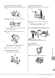
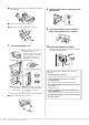
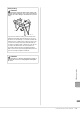
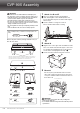
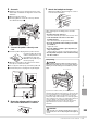
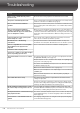
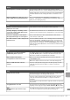
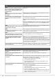
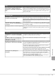
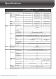
Table Of Contents
- PRECAUTIONS
- NOTICE
- Information
- Compatible formats for this instrument
- About the Manuals
- Included Accessories
- Contents
- Welcome to the World of CVP!
- Panel Controls
- Starting Up
- Basic Operations
- Display Structure
- Display Configuration
- Closing the Current Display
- Display-based Controls
- Using the ASSIGNABLE Buttons
- File Management
- Entering Characters
- Using the Pedals
- Using the Metronome
- Adjusting the Tempo
- Setting the Touch Sensitivity of the Keyboard
- Transposing the Pitch in Semitones
- Adjusting the Volume Balance
- Restoring the Factory-programmed Settings (Initializing)
- Data Backup
- Piano Room – Enjoying the Piano Performance –
- Voices – Playing the Keyboard –
- Styles – Playing Rhythm and Accompaniment –
- Song Playback – Playing and Practice Songs –
- Song Recording – Recording Your Performance –
- Microphone – Adding Vocal Harmony Effects to Your Singing –
- Registration Memory/Playlist – Saving and Recalling Custom Panel Setups –
- Mixer – Editing the Volume and Tonal Balance –
- Connections – Using Your Instrument with Other Devices –
- I/O Connectors
- Connecting USB Devices ([USB TO DEVICE] terminal)
- Connecting to a Computer ([USB TO HOST] terminal)
- Connecting to a Smart Device ([AUX IN] jack/Bluetooth/[USB TO HOST] terminal/Wireless LAN)
- Listening to Audio Playback by the External Device through the Instrument’s Speaker ([AUX IN] jack/Bluetooth/[USB TO HOST] terminal)
- Using an External Speaker System for Playback (AUX OUT [L/L+R]/[R] jacks)
- Connecting External MIDI Devices (MIDI terminals)
- Viewing the Instrument’s Display on an External Monitor
- Connecting a Microphone or Guitar ([MIC/LINE IN] jack)
- Connecting a Footswitch/Foot Controller ([AUX PEDAL] jack)
- Menu Display Function List
- CVP-909 (Grand piano type) Assembly
- CVP-909 Assembly
- CVP-905 Assembly
- Troubleshooting
- Specifications
- Index

CVP-909/CVP-905 Owner’s Manual
122
3 Pass the pedal cord from under unit D to the backside
of the main unit.
4 Place unit F on the bracket of unit D.
5 Attach unit F to unit D using three screws M.
7 Connect the pedal cord.
4 Attach unit G using two screws N.
8 Insert the AC power cord plug into the
[AC IN] jack.
9 Rotate the adjuster until it comes in
firm contact with the floor surface.
10 Attach the headphone hanger.
Attach the headphone hanger using two screws P
as shown in the illustration.
3
4
M
1 Insert the pedal cord plug into
the pedal connector.
Insert the pedal cord securely
until the metal part of the cord
plug disappears from view.
Otherwise, the pedal may not
function properly.
2 Pass the pedal
cord between
units D and E.
3 Align the pedal cord into the
groove on unit D, then install
the cover onto the groove
correctly.
Correct
Incorrect
4
GG
N
After completing the assembly, please check the
following.
• Are there any parts left over?
Review the assembly procedure and correct any errors.
• Is the instrument clear of doors and other
movable fixtures?
Move the instrument to an appropriate location.
• Does the instrument make a rattling noise when
you shake it?
Tighten all screws.
• Does the pedal box rattle or give way when you
step on the pedals?
Turn the adjuster so that it is set firmly against the floor.
• Are the pedal and power cords inserted securely
into the sockets?
P