
User Manual


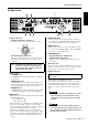

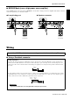

Table Of Contents

T5n/T4n/T3n Owner’s Manual
7
Controls and Functions
■
Rear Panel
1
Input connectors
• XLR3-31 type input connectors
The pins are wired as shown below (IEC 60268).
• Euroblock input connectors
These are balanced input connectors. The included
Euroblock connectors can be used to make connec-
tions here.
2
Mode switch
• STEREO mode
In STEREO mode, channels A and B are completely
independent.
•PARALLEL mode
In PARALLEL mode, the channel A input signal is sent
both to the channel A power amp and the channel B amp.
The Channel B input connector does not function.
• BRIDGE mode
In BRIDGE mode, channels A and B operates simul-
taneously, functioning as a single mono amplifier.
3
GAIN switch
This switch is used when changing the Gain of the A and B
channels simultaneously.
32 dB: Setting of 32 dB
26 dB: Setting of 26 dB
When monitoring or controlling from an amplifier control
device such as the ACD1 or ACU16-C, set the GAIN
switch to [26 dB] to avoid clipping if you plan to input sig-
nals with a maximum input level of +24 dBu.
When the power amplifier is connected to the ACD1 or
ACU16-C, the electronic volume control inside the ampli-
fier will become effective, and the maximum input level
will become +18 dBu if the GAIN switch has been set to
[32 dB].
4
DATA PORT jacks
An amp control device, such as the ACD1 or ACU16-C,
can be connected to the DATA PORT jack for monitoring
or controlling the amplifier from the external device.
5
AMP ID switch
When an amp control device, such as the ACD1 or ACU16-
C, is connected to the DATA PORT jack
4
, the AMP ID
can be used to set the amplifier’s ID.
6
SPEAKERS jacks
• 5-way binding post output jacks
• Speakon type output jacks
Speakon type cable plugs (Neutrik NL4) can be con-
nected here.
7
Ground screw
If you are having a problem with hum or noise, use this ter-
minal to connect to ground or connect to the chassis of the
mixer, preamp, or other device in your system.
8
AC IN connector
This amplifier uses a NEMA L5-30 outlet.
Connect the 30 A twist-lock connectors by orienting the
locking L-shaped prong with the corresponding connector
entry, then fully insert the three prongs. Twist the plug
about 1/8 of a turn clockwise to lock the connector and
plug.
The amplifier requires very high-power so that it
can demand high current from the AC service.
Connections must be properly rated for reliable
operation.
If this device is to be rack mounted and trans-
ported frequently, be sure to support the rear end
of the unit with mounting hardware that matches
the size of the rack used.
4 5
32
178
6
Note: In PARALLEL and BRIDGE mode, only the
channel A connector is active. Make sure
not to input an audio signal to an inactive
input terminal (channel B).
Ground
Cold
Hot
Amplifiers purchased in the United States of America
and Canada.